EP1178245A1 - Transmission for a vehicle and method of controlling the same - Google Patents
Transmission for a vehicle and method of controlling the same Download PDFInfo
- Publication number
- EP1178245A1 EP1178245A1 EP01116546A EP01116546A EP1178245A1 EP 1178245 A1 EP1178245 A1 EP 1178245A1 EP 01116546 A EP01116546 A EP 01116546A EP 01116546 A EP01116546 A EP 01116546A EP 1178245 A1 EP1178245 A1 EP 1178245A1
- Authority
- EP
- European Patent Office
- Prior art keywords
- transmission
- gear
- vehicle
- change
- control device
- Prior art date
- Legal status (The legal status is an assumption and is not a legal conclusion. Google has not performed a legal analysis and makes no representation as to the accuracy of the status listed.)
- Granted
Links
- 230000005540 biological transmission Effects 0.000 title claims abstract description 212
- 238000000034 method Methods 0.000 title claims description 16
- 230000007935 neutral effect Effects 0.000 claims description 38
- 230000002159 abnormal effect Effects 0.000 claims description 8
- MROJXXOCABQVEF-UHFFFAOYSA-N Actarit Chemical compound CC(=O)NC1=CC=C(CC(O)=O)C=C1 MROJXXOCABQVEF-UHFFFAOYSA-N 0.000 claims 11
- 238000009825 accumulation Methods 0.000 description 40
- 239000000243 solution Substances 0.000 description 23
- 238000010586 diagram Methods 0.000 description 17
- 230000001105 regulatory effect Effects 0.000 description 12
- 230000006870 function Effects 0.000 description 11
- 230000001276 controlling effect Effects 0.000 description 10
- 239000012530 fluid Substances 0.000 description 10
- 238000010276 construction Methods 0.000 description 4
- 238000006073 displacement reaction Methods 0.000 description 4
- 230000035939 shock Effects 0.000 description 4
- 239000000446 fuel Substances 0.000 description 3
- 238000002347 injection Methods 0.000 description 3
- 239000007924 injection Substances 0.000 description 3
- 239000003921 oil Substances 0.000 description 3
- 230000015556 catabolic process Effects 0.000 description 2
- 239000002826 coolant Substances 0.000 description 2
- 238000006731 degradation reaction Methods 0.000 description 2
- 230000006386 memory function Effects 0.000 description 2
- 238000005096 rolling process Methods 0.000 description 2
- 239000007858 starting material Substances 0.000 description 2
- 101100309712 Arabidopsis thaliana SD11 gene Proteins 0.000 description 1
- 230000005856 abnormality Effects 0.000 description 1
- 230000003466 anti-cipated effect Effects 0.000 description 1
- 238000004891 communication Methods 0.000 description 1
- 239000010687 lubricating oil Substances 0.000 description 1
- 238000012986 modification Methods 0.000 description 1
- 230000004048 modification Effects 0.000 description 1
- 238000012545 processing Methods 0.000 description 1
- 238000012360 testing method Methods 0.000 description 1
Images






Classifications
-
- F—MECHANICAL ENGINEERING; LIGHTING; HEATING; WEAPONS; BLASTING
- F16—ENGINEERING ELEMENTS AND UNITS; GENERAL MEASURES FOR PRODUCING AND MAINTAINING EFFECTIVE FUNCTIONING OF MACHINES OR INSTALLATIONS; THERMAL INSULATION IN GENERAL
- F16H—GEARING
- F16H61/00—Control functions within control units of change-speed- or reversing-gearings for conveying rotary motion ; Control of exclusively fluid gearing, friction gearing, gearings with endless flexible members or other particular types of gearing
- F16H61/12—Detecting malfunction or potential malfunction, e.g. fail safe ; Circumventing or fixing failures
-
- F—MECHANICAL ENGINEERING; LIGHTING; HEATING; WEAPONS; BLASTING
- F16—ENGINEERING ELEMENTS AND UNITS; GENERAL MEASURES FOR PRODUCING AND MAINTAINING EFFECTIVE FUNCTIONING OF MACHINES OR INSTALLATIONS; THERMAL INSULATION IN GENERAL
- F16H—GEARING
- F16H59/00—Control inputs to control units of change-speed- or reversing-gearings for conveying rotary motion
- F16H59/36—Inputs being a function of speed
- F16H59/44—Inputs being a function of speed dependent on machine speed, e.g. the vehicle speed
- F16H2059/446—Detecting vehicle stop, i.e. the vehicle is at stand still, e.g. for engaging parking lock
-
- F—MECHANICAL ENGINEERING; LIGHTING; HEATING; WEAPONS; BLASTING
- F16—ENGINEERING ELEMENTS AND UNITS; GENERAL MEASURES FOR PRODUCING AND MAINTAINING EFFECTIVE FUNCTIONING OF MACHINES OR INSTALLATIONS; THERMAL INSULATION IN GENERAL
- F16H—GEARING
- F16H61/00—Control functions within control units of change-speed- or reversing-gearings for conveying rotary motion ; Control of exclusively fluid gearing, friction gearing, gearings with endless flexible members or other particular types of gearing
- F16H61/12—Detecting malfunction or potential malfunction, e.g. fail safe ; Circumventing or fixing failures
- F16H2061/1208—Detecting malfunction or potential malfunction, e.g. fail safe ; Circumventing or fixing failures with diagnostic check cycles; Monitoring of failures
-
- F—MECHANICAL ENGINEERING; LIGHTING; HEATING; WEAPONS; BLASTING
- F16—ENGINEERING ELEMENTS AND UNITS; GENERAL MEASURES FOR PRODUCING AND MAINTAINING EFFECTIVE FUNCTIONING OF MACHINES OR INSTALLATIONS; THERMAL INSULATION IN GENERAL
- F16H—GEARING
- F16H61/00—Control functions within control units of change-speed- or reversing-gearings for conveying rotary motion ; Control of exclusively fluid gearing, friction gearing, gearings with endless flexible members or other particular types of gearing
- F16H61/12—Detecting malfunction or potential malfunction, e.g. fail safe ; Circumventing or fixing failures
- F16H2061/122—Avoiding failures by using redundant parts
-
- F—MECHANICAL ENGINEERING; LIGHTING; HEATING; WEAPONS; BLASTING
- F16—ENGINEERING ELEMENTS AND UNITS; GENERAL MEASURES FOR PRODUCING AND MAINTAINING EFFECTIVE FUNCTIONING OF MACHINES OR INSTALLATIONS; THERMAL INSULATION IN GENERAL
- F16H—GEARING
- F16H61/00—Control functions within control units of change-speed- or reversing-gearings for conveying rotary motion ; Control of exclusively fluid gearing, friction gearing, gearings with endless flexible members or other particular types of gearing
- F16H61/12—Detecting malfunction or potential malfunction, e.g. fail safe ; Circumventing or fixing failures
- F16H2061/1224—Adapting to failures or work around with other constraints, e.g. circumvention by avoiding use of failed parts
-
- F—MECHANICAL ENGINEERING; LIGHTING; HEATING; WEAPONS; BLASTING
- F16—ENGINEERING ELEMENTS AND UNITS; GENERAL MEASURES FOR PRODUCING AND MAINTAINING EFFECTIVE FUNCTIONING OF MACHINES OR INSTALLATIONS; THERMAL INSULATION IN GENERAL
- F16H—GEARING
- F16H61/00—Control functions within control units of change-speed- or reversing-gearings for conveying rotary motion ; Control of exclusively fluid gearing, friction gearing, gearings with endless flexible members or other particular types of gearing
- F16H61/12—Detecting malfunction or potential malfunction, e.g. fail safe ; Circumventing or fixing failures
- F16H2061/1232—Bringing the control into a predefined state, e.g. giving priority to particular actuators or gear ratios
-
- F—MECHANICAL ENGINEERING; LIGHTING; HEATING; WEAPONS; BLASTING
- F16—ENGINEERING ELEMENTS AND UNITS; GENERAL MEASURES FOR PRODUCING AND MAINTAINING EFFECTIVE FUNCTIONING OF MACHINES OR INSTALLATIONS; THERMAL INSULATION IN GENERAL
- F16H—GEARING
- F16H61/00—Control functions within control units of change-speed- or reversing-gearings for conveying rotary motion ; Control of exclusively fluid gearing, friction gearing, gearings with endless flexible members or other particular types of gearing
- F16H61/12—Detecting malfunction or potential malfunction, e.g. fail safe ; Circumventing or fixing failures
- F16H2061/1256—Detecting malfunction or potential malfunction, e.g. fail safe ; Circumventing or fixing failures characterised by the parts or units where malfunctioning was assumed or detected
- F16H2061/126—Detecting malfunction or potential malfunction, e.g. fail safe ; Circumventing or fixing failures characterised by the parts or units where malfunctioning was assumed or detected the failing part is the controller
- F16H2061/1264—Hydraulic parts of the controller, e.g. a sticking valve or clogged channel
-
- F—MECHANICAL ENGINEERING; LIGHTING; HEATING; WEAPONS; BLASTING
- F16—ENGINEERING ELEMENTS AND UNITS; GENERAL MEASURES FOR PRODUCING AND MAINTAINING EFFECTIVE FUNCTIONING OF MACHINES OR INSTALLATIONS; THERMAL INSULATION IN GENERAL
- F16H—GEARING
- F16H61/00—Control functions within control units of change-speed- or reversing-gearings for conveying rotary motion ; Control of exclusively fluid gearing, friction gearing, gearings with endless flexible members or other particular types of gearing
- F16H61/12—Detecting malfunction or potential malfunction, e.g. fail safe ; Circumventing or fixing failures
- F16H2061/1256—Detecting malfunction or potential malfunction, e.g. fail safe ; Circumventing or fixing failures characterised by the parts or units where malfunctioning was assumed or detected
- F16H2061/126—Detecting malfunction or potential malfunction, e.g. fail safe ; Circumventing or fixing failures characterised by the parts or units where malfunctioning was assumed or detected the failing part is the controller
- F16H2061/1268—Electric parts of the controller, e.g. a defect solenoid, wiring or microprocessor
-
- F—MECHANICAL ENGINEERING; LIGHTING; HEATING; WEAPONS; BLASTING
- F16—ENGINEERING ELEMENTS AND UNITS; GENERAL MEASURES FOR PRODUCING AND MAINTAINING EFFECTIVE FUNCTIONING OF MACHINES OR INSTALLATIONS; THERMAL INSULATION IN GENERAL
- F16H—GEARING
- F16H61/00—Control functions within control units of change-speed- or reversing-gearings for conveying rotary motion ; Control of exclusively fluid gearing, friction gearing, gearings with endless flexible members or other particular types of gearing
- F16H61/12—Detecting malfunction or potential malfunction, e.g. fail safe ; Circumventing or fixing failures
- F16H2061/1256—Detecting malfunction or potential malfunction, e.g. fail safe ; Circumventing or fixing failures characterised by the parts or units where malfunctioning was assumed or detected
- F16H2061/1272—Detecting malfunction or potential malfunction, e.g. fail safe ; Circumventing or fixing failures characterised by the parts or units where malfunctioning was assumed or detected the failing part is a part of the final output mechanism, e.g. shift rods or forks
-
- F—MECHANICAL ENGINEERING; LIGHTING; HEATING; WEAPONS; BLASTING
- F16—ENGINEERING ELEMENTS AND UNITS; GENERAL MEASURES FOR PRODUCING AND MAINTAINING EFFECTIVE FUNCTIONING OF MACHINES OR INSTALLATIONS; THERMAL INSULATION IN GENERAL
- F16H—GEARING
- F16H61/00—Control functions within control units of change-speed- or reversing-gearings for conveying rotary motion ; Control of exclusively fluid gearing, friction gearing, gearings with endless flexible members or other particular types of gearing
- F16H61/12—Detecting malfunction or potential malfunction, e.g. fail safe ; Circumventing or fixing failures
- F16H2061/1256—Detecting malfunction or potential malfunction, e.g. fail safe ; Circumventing or fixing failures characterised by the parts or units where malfunctioning was assumed or detected
- F16H2061/1276—Detecting malfunction or potential malfunction, e.g. fail safe ; Circumventing or fixing failures characterised by the parts or units where malfunctioning was assumed or detected the failing part is a friction device, e.g. clutches or brakes
- F16H2061/128—Detecting malfunction or potential malfunction, e.g. fail safe ; Circumventing or fixing failures characterised by the parts or units where malfunctioning was assumed or detected the failing part is a friction device, e.g. clutches or brakes the main clutch
-
- F—MECHANICAL ENGINEERING; LIGHTING; HEATING; WEAPONS; BLASTING
- F16—ENGINEERING ELEMENTS AND UNITS; GENERAL MEASURES FOR PRODUCING AND MAINTAINING EFFECTIVE FUNCTIONING OF MACHINES OR INSTALLATIONS; THERMAL INSULATION IN GENERAL
- F16H—GEARING
- F16H61/00—Control functions within control units of change-speed- or reversing-gearings for conveying rotary motion ; Control of exclusively fluid gearing, friction gearing, gearings with endless flexible members or other particular types of gearing
- F16H61/12—Detecting malfunction or potential malfunction, e.g. fail safe ; Circumventing or fixing failures
- F16H2061/1256—Detecting malfunction or potential malfunction, e.g. fail safe ; Circumventing or fixing failures characterised by the parts or units where malfunctioning was assumed or detected
- F16H2061/1284—Detecting malfunction or potential malfunction, e.g. fail safe ; Circumventing or fixing failures characterised by the parts or units where malfunctioning was assumed or detected the failing part is a sensor
-
- F—MECHANICAL ENGINEERING; LIGHTING; HEATING; WEAPONS; BLASTING
- F16—ENGINEERING ELEMENTS AND UNITS; GENERAL MEASURES FOR PRODUCING AND MAINTAINING EFFECTIVE FUNCTIONING OF MACHINES OR INSTALLATIONS; THERMAL INSULATION IN GENERAL
- F16H—GEARING
- F16H61/00—Control functions within control units of change-speed- or reversing-gearings for conveying rotary motion ; Control of exclusively fluid gearing, friction gearing, gearings with endless flexible members or other particular types of gearing
- F16H61/12—Detecting malfunction or potential malfunction, e.g. fail safe ; Circumventing or fixing failures
- F16H2061/1256—Detecting malfunction or potential malfunction, e.g. fail safe ; Circumventing or fixing failures characterised by the parts or units where malfunctioning was assumed or detected
- F16H2061/1288—Detecting malfunction or potential malfunction, e.g. fail safe ; Circumventing or fixing failures characterised by the parts or units where malfunctioning was assumed or detected the failing part is an actuator
-
- F—MECHANICAL ENGINEERING; LIGHTING; HEATING; WEAPONS; BLASTING
- F16—ENGINEERING ELEMENTS AND UNITS; GENERAL MEASURES FOR PRODUCING AND MAINTAINING EFFECTIVE FUNCTIONING OF MACHINES OR INSTALLATIONS; THERMAL INSULATION IN GENERAL
- F16H—GEARING
- F16H61/00—Control functions within control units of change-speed- or reversing-gearings for conveying rotary motion ; Control of exclusively fluid gearing, friction gearing, gearings with endless flexible members or other particular types of gearing
- F16H61/16—Inhibiting or initiating shift during unfavourable conditions , e.g. preventing forward-reverse shift at high vehicle speed, preventing engine overspeed
- F16H2061/168—Forced shifts into neutral for safety reasons, e.g. in case of transmission failure or emergency braking
-
- F—MECHANICAL ENGINEERING; LIGHTING; HEATING; WEAPONS; BLASTING
- F16—ENGINEERING ELEMENTS AND UNITS; GENERAL MEASURES FOR PRODUCING AND MAINTAINING EFFECTIVE FUNCTIONING OF MACHINES OR INSTALLATIONS; THERMAL INSULATION IN GENERAL
- F16H—GEARING
- F16H61/00—Control functions within control units of change-speed- or reversing-gearings for conveying rotary motion ; Control of exclusively fluid gearing, friction gearing, gearings with endless flexible members or other particular types of gearing
- F16H61/16—Inhibiting or initiating shift during unfavourable conditions , e.g. preventing forward-reverse shift at high vehicle speed, preventing engine overspeed
-
- F—MECHANICAL ENGINEERING; LIGHTING; HEATING; WEAPONS; BLASTING
- F16—ENGINEERING ELEMENTS AND UNITS; GENERAL MEASURES FOR PRODUCING AND MAINTAINING EFFECTIVE FUNCTIONING OF MACHINES OR INSTALLATIONS; THERMAL INSULATION IN GENERAL
- F16H—GEARING
- F16H61/00—Control functions within control units of change-speed- or reversing-gearings for conveying rotary motion ; Control of exclusively fluid gearing, friction gearing, gearings with endless flexible members or other particular types of gearing
- F16H61/26—Generation or transmission of movements for final actuating mechanisms
- F16H61/28—Generation or transmission of movements for final actuating mechanisms with at least one movement of the final actuating mechanism being caused by a non-mechanical force, e.g. power-assisted
- F16H61/2807—Generation or transmission of movements for final actuating mechanisms with at least one movement of the final actuating mechanism being caused by a non-mechanical force, e.g. power-assisted using electric control signals for shift actuators, e.g. electro-hydraulic control therefor
-
- F—MECHANICAL ENGINEERING; LIGHTING; HEATING; WEAPONS; BLASTING
- F16—ENGINEERING ELEMENTS AND UNITS; GENERAL MEASURES FOR PRODUCING AND MAINTAINING EFFECTIVE FUNCTIONING OF MACHINES OR INSTALLATIONS; THERMAL INSULATION IN GENERAL
- F16H—GEARING
- F16H61/00—Control functions within control units of change-speed- or reversing-gearings for conveying rotary motion ; Control of exclusively fluid gearing, friction gearing, gearings with endless flexible members or other particular types of gearing
- F16H61/68—Control functions within control units of change-speed- or reversing-gearings for conveying rotary motion ; Control of exclusively fluid gearing, friction gearing, gearings with endless flexible members or other particular types of gearing specially adapted for stepped gearings
- F16H61/682—Control functions within control units of change-speed- or reversing-gearings for conveying rotary motion ; Control of exclusively fluid gearing, friction gearing, gearings with endless flexible members or other particular types of gearing specially adapted for stepped gearings with interruption of drive
Definitions
- the aforementioned control device can take measures against only a limited number of inconveniences and requires operation of the manual operation member to take measures against abnormalities of a certain type.
- a control device is difficult to handle especially for a driver who has driven only vehicles equipped with an automatic transmission or who can drive only vehicles equipped with an automatic transmission.
- the invention has been made as a solution to the problem described above. It is an object of the invention to provide a control device for transmission and a method of controlling automatic transmission in which some or all of gear-change operations are performed automatically with a control device that can automatically take measures against a not-normal state.
- the differential 18 is of a bevel gear type wherein drive shafts 82R, 82L are connected to side gears 80R, 80L respectively through spline fitting or the like so as to rotationally drive left-front and right-front wheels (driving wheels) 84R, 84L or rear-front and rear-right wheels (driving wheels) 84R, 84L respectively.
- the hydraulic pressure P A in the pressure accumulation unit 90 is supplied to a clutch solenoid valve 98 and a pressure regulating valve 95, and thus corresponds to original pressures in the shift cylinder 78 and the select cylinder 76 that perform gear-change of the transmission 16 and in the clutch release cylinder 34 that drives the automatic clutch 14.
- the select cylinder 76 selectively connects the shift-select shaft (not shown) to one of shift forks engaging the clutch hub sleeves 50a, 50b and 50c, e.g. by axially displacing the shift-select shaft (not shown).
- the shift cylinder 78 displaces one of the clutch hub sleeves 50a, 50b and 50c to its engagement position or its neutral position, e.g. by rotationally displacing the shift-select shaft (not shown) to one of the three positions, i.e., the shift positions and the neutral center position therebetween.
- the hydraulic pump operation state changing means 226 has hydraulic pump initial drive means 228, gear-change number determining means 230, elapsed time determining means 232, and hydraulic pump intermittent drive control means 234. If the original pressure sensor state determining means 224 determines that the original pressure sensor 92 is not normal, the hydraulic pump initial drive means 228 drives the hydraulic pump 94 for a certain time T 1 , thus increasing the hydraulic pressure P A in the pressure accumulation unit 90 by a predetermined pressure before intermittently driving the hydraulic pump 94.
- the gear-change number determining means 230 determines whether or not the gear-change number n SH of the transmission 16 has exceeded a predetermined number N.
- the hydraulic pump operation state changing means 226 changes, based on an amount of consumption of hydraulic fluid at the original pressure P A , the operation state of the hydraulic pump 94 into an intermittent operation state where the hydraulic pump 94 is operated for the predetermined time T 2 that has been set so as to compensate for the amount of consumption.
- the hydraulic pump 94 is operated for the predetermined time T 2 that has been set so as to compensate for the amount of consumption. Therefore, the original pressure is maintained according to necessity and to a sufficient degree.
Landscapes
- Engineering & Computer Science (AREA)
- General Engineering & Computer Science (AREA)
- Mechanical Engineering (AREA)
- Control Of Transmission Device (AREA)
Abstract
Description
- The invention relates to a transmission exclusively using a clutch for connecting to an engine of a vehicle, and more particularly, to a control device of such a transmission which performs gear-change automatically using a clutch actuator, a shift actuator and a select actuator.
- Control devices designed to control a vehicular transmission that is provided in a power transmission path between a prime mover and driving wheels are known. In one of such control devices, various elements such as an automatic clutch and/or a transmission and the like are controlled automatically by an electronic control unit via various actuators, whereby some or all of a series of gear-change operations are performed automatically. One such device has been proposed in which an emergency manual operation member capable of releasing and engaging the automatic clutch or performing gear-change of the transmission manually if the elements have become unable to be controlled automatically due to inconveniences of the electronic control unit or the actuators is provided as emergency back-up means and wherein the emergency manual operation member is used effectively when the vehicle is stopped. For example, such a device is disclosed in Patent Publication No. 2820732.
- However, the aforementioned control device according to the related art can take measures against only a limited number of inconveniences and requires operation of the manual operation member to take measures against abnormalities of a certain type. Thus, such a control device is difficult to handle especially for a driver who has driven only vehicles equipped with an automatic transmission or who can drive only vehicles equipped with an automatic transmission.
- The invention has been made as a solution to the problem described above. It is an object of the invention to provide a control device for transmission and a method of controlling automatic transmission in which some or all of gear-change operations are performed automatically with a control device that can automatically take measures against a not-normal state.
- The object is for example solved by a transmission for a vehicle which is provided in a power transmission path extending from a prime mover to driving wheels, and which is connectable to said prime mover by exclusively using an automatically actuable clutch, comprising: a control device for automatically controlling gear-change of said transmission; and state determining means for determining an abnormal condition of said control device, wherein said control device starts a fail-safe operation, when said state determining means detects an abnormal condition of said control device, which enables at least a restricted automatic driving operation.
- According to a further solution of the object of the invention in the fail-safe operation of the transmission, a gear-change is permitted, when the vehicle is stopped and a gear-change is prohibited, when the vehicle is not stopped.
- According to a further solution of the object of the invention in the fail-safe operation of the transmission, a gear-change is permitted, when the vehicle runs at a speed equal to or lower than a predetermined vehicle speed and a gear-change is prohibited, when the vehicle runs at a speed higher than the predetermined vehicle speed.
- According to a further solution of the object of the invention, when a gear-change is permitted, the gear-change is constricted to a gear-change between a first gear and a neutral gear, between a second gear and the neutral gear, or between a reverse gear and the neutral gear.
- According to a further solution of the object of the invention in the fail-safe operation of the transmission, an engagement of said automatic clutch provided between the prime mover and the transmission is released, when a vehicle speed is below a predetermined speed, and a gear parking requirement has not been made.
- According to a further solution of the object of the invention in the fail-safe operation of the transmission, an engagement of said automatic clutch provided between the prime mover and the transmission is released, when an engine of the vehicle is not operating, and an ignition key is turned on.
- According to a further solution of the object of the invention in the fail-safe operation of the transmission, an engagement of said automatic clutch provided between the prime mover and the transmission is established, when a vehicle speed is above a predetermined speed, and an engine of the vehicle is operating.
- According to a further solution of the object of the invention in the fail-safe operation of the transmission, an engagement of said automatic clutch provided between the prime mover and the transmission is established, when a vehicle speed is below a predetermined speed, and a gear parking requirement has been made.
- According to a further solution of the object of the invention in the fail-safe operation of the transmission, an engagement of said automatic clutch provided between the prime mover and the transmission is established, when a vehicle speed is above a predetermined speed, an engine of the vehicle is not operating, and an ignition key is turned off.
- According to a further solution of the object of the invention in the fail-safe operation of the transmission, when a failure of a clutch control device is detected by a clutch control system state determining means, a shift control device of the transmission automatically establishes a neutral state in the transmission.
- According to a further solution of the object of the invention the shift control device of the transmission automatically establishes a neutral state in the transmission, when the clutch control device for controlling the automatic clutch is not normal.
- According to a further solution of the object of the invention the transmission further comprises a hydraulic pump for generating an original pressure; an original pressure sensor for detecting the original pressure; and a control hydraulic pressure sensor for detecting a control hydraulic pressure.
- According to a further solution of the object of the invention the original pressure is reduced, when a failure in said control hydraulic pressure sensor is detected.
- According to a further solution of the object of the invention the hydraulic pump is operated for a first predetermined time T1, when a failure in said original pressure sensor is detected.
- According to a further solution of the object of the invention the hydraulic pump is further operated for a second predetermined time T2, when a gear-change number exceeds a predetermined number.
- According to a further solution of the object of the invention the hydraulic pump is further operated for a second predetermined time T2, when an elapsed time exceeds a third predetermined time T3.
- According to a further solution of the object of the invention the control device determines that the vehicle is not in a normal running state if a rotational speed (VW1) of a right non-driving wheel is lower than a first reference value (V1), if a rotational speed (VW2) of a left non-driving wheel is lower than a second reference value (V2), and if a rotational speed (VW3) of a right driving wheel is higher than a third reference value (V3) or if a rotational speed (VW4) of a left driving wheel is higher than a fourth reference value (V4).
- According to a further solution of the object of the invention there is provided a method of controlling a transmission for a vehicle which is provided in a power transmission path extending from a prime mover to driving wheels, and which is connectable to said prime mover by exclusively using an automatically actuable clutch, comprising the steps of automatically controlling gear-change of the transmission, wherein the method further comprises the steps of: detecting an abnormal condition of a control device of said transmission, starting a fail-safe operation of the transmission, when an abnormal condition of said control device is detected, which enables at least a restricted automatic driving operation.
- According to a further solution of the object of the invention there is provided a method, wherein in the fail-safe operation of the transmission, a gear-change is permitted, when the vehicle is stopped and a gear-change is prohibited, when the vehicle is not stopped.
- According to a further solution of the object of the invention there is provided a method, wherein in the fail-safe operation of the transmission, said automatic clutch provided between said prime mover and the transmission is released.
- According to a further solution of the object of the invention there is provided a method, wherein in the fail-safe operation of the transmission, when a failure of a clutch control device is detected by a clutch control system state determining means, a shift control device of the transmission automatically establishes a neutral state in the transmission.
- According to a further solution of the object of the invention there is provided a method, wherein an original pressure of a pressure generating means is reduced, when a failure in an original pressure sensor that detects an original pressure (PA) for driving the control device is detected.
- According to a further solution of the object of the invention there is provided a method, wherein the control device determines that the vehicle is not in a normal running state if a rotational speed (VW1) of a right non-driving wheel is lower than a first reference value (V1), if a rotational speed (VW2) of a left non-driving wheel is lower than a second reference value (V2), and if a rotational speed (VW3) of a right driving wheel is higher than a third reference value (V3) or if a rotational speed (VW4) of a left driving wheel is higher than a fourth reference value (V4).
- An aspect of the invention aiming at achieving the object consists in that, if an automatic gear-change control device for a transmission that is employed in a vehicle and that is provided in a power transmission path extending from a prime mover to driving wheels is not normal, gear-change is prohibited automatically when the vehicle is not stopped and gear-change is permitted automatically when the vehicle is stopped.
- Thus, if the automatic gear-change control device for the transmission is not normal, e.g., if at least one of an automatic clutch, a shift device, a select device, actuators for those components, detectors for detecting operations by the actuators, and the like is not normal, gear-change is prohibited automatically when the vehicle is running, whereby gear-change is prevented from being performed against the intention of a driver while the vehicle is running. Thus, security is enhanced. If the vehicle has been stopped, gear-change is permitted automatically, whereby the vehicle is allowed to restart quickly.
- The objects, features, advantages, technical and industrial significance of this invention will be better understood by reading the following detailed description of preferred embodiments of the invention, when considered in connection with the accompanying drawings, in which:
- Fig. 1 is a skeleton diagram showing an overall construction of a vehicular driving unit to which control devices according to embodiments of the invention are applied;
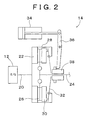
- Fig. 2 is an illustrative view of a construction of an automatic clutch of the vehicular driving unit shown in Fig. 1;
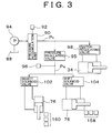
- Fig. 3 is an illustrative view of a hydraulic control circuit for controlling operation of the automatic clutch and a transmission shown in Fig. 1;
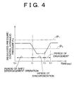
- Fig. 4 illustrates how a driving control hydraulic pressure that is regulated by a pressure-regulating valve shown in Fig. 3 to set an appropriate shift load changes in a shift period of the transmission shown in Fig. 1;
- Fig. 5 is a block diagram illustrating a control system of the vehicular driving unit shown in Fig. 1;
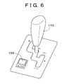
- Fig. 6 is a perspective view illustrating a shift lever that is employed in the vehicular driving unit shown in Fig. 1;
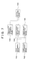
- Fig. 7 is a functional block diagram illustrating the essence of a control function of a transmission electronic control unit according to a first embodiment of the invention;
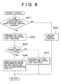
- Fig. 8 is a flowchart illustrating the essence of control operation of the transmission electronic control unit according to the first embodiment of the invention;
- Fig. 9 is a functional block diagram illustrating the essence of a control function of a transmission electronic control unit according to a second embodiment of the invention and corresponds to Fig. 7;
- Fig. 10 is a flowchart illustrating the essence of control operation of the transmission electronic control unit according to the second embodiment of the invention;
- Fig. 11 is a functional block diagram illustrating the essence of a control function of a transmission electronic control unit according to a third embodiment of the invention and corresponds to Fig. 7;
- Fig. 12 is a flowchart illustrating the essence of control operation of the transmission electronic control unit according to the third embodiment of the invention;
- Fig. 13 is a functional block diagram illustrating the essence of a control function of a transmission electronic control unit according to a fourth embodiment of the invention and corresponds to Fig. 7;
- Fig. 14 is a flowchart illustrating the essence of control operation of the transmission electronic control unit according to the fourth embodiment of the invention;
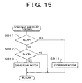
- Fig. 15 is a flowchart illustrating operation of normal pressure accumulation control shown in Fig. 14;
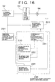
- Fig. 16 is a functional block diagram illustrating the essence of a control function of a transmission electronic control unit according to a fifth embodiment of the invention and corresponds to Fig. 7;
- Fig. 17 is a flowchart illustrating the essence of control operation of the transmission electronic control unit according to the fifth embodiment of the invention;
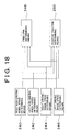
- Fig. 18 is a functional block diagram illustrating the essence of a control function of a transmission electronic control unit according to a sixth embodiment of the invention and corresponds to Fig. 7; and
- Fig. 19 is a flowchart illustrating the essence of control operation of the transmission electronic control unit according to the sixth embodiment of the invention;
-
- In the following description and the accompanying drawings, the invention will be described in more detail with reference to exemplary, preferred embodiments.
- Hereinafter, embodiments of the invention will be described in detail with reference to the drawings.
- Fig. 1 is a skeleton diagram illustrating an overall construction of a
vehicular driving unit 10 to which control devices according to the embodiments of the invention are applied. Although this vehicular driving unit is designed for an FF (front-engine front-drive) vehicle or an MR (mid-engine rear-drive) vehicle, it is applicable not only to the FF or MR vehicle but also to an FR (front-engine front-drive) vehicle and an RR (rear-engine rear-drive) vehicle. Referring to Fig. 1, thevehicular driving unit 10 has anengine 12 as a prime mover or a traction drive source, anautomatic clutch 14, atransmission 16, and a differential 18. Theautomatic clutch 14 is for example a friction clutch made of a single dry plate, and includes aflywheel 22 fitted to acrankshaft 20 of theengine 12, aclutch disc 26 disposed on aclutch output shaft 24, apressure plate 30 disposed in aclutch housing 28, adiaphragm spring 32 that clamps theclutch disc 26 by urging thepressure plate 30 toward theflywheel 22 and that transmits power, and arelease sleeve 38 that displaces an inner end portion of thediaphragm spring 32 to the left in Fig. 1 by being displaced to the left in Fig. 1 by aclutch release cylinder 34 via arelease fork 36 and that releases (disengages) clutches. - The
transmission 16 is disposed in acommon housing 40 together with the differential 18 to constitute a part of a transaxle, and is soaked in a selected amount of lubricating oil filling thehousing 40 so as to be lubricated together with the differential 18. Thetransmission 16 has a two-parallel-shaft normal-engaged transmission mechanism (a) and a shift-select shaft (b) (not shown), and is capable of establishing five forward gear-change stages. The two-parallel-shaft normal-engaged transmission mechanism (a) has a plurality of normally engaged gear-change gear pairs 46a to 46e that are different in gear ratio from one another disposed between aninput shaft 42 and anoutput shaft 44 that are parallel to each other, and is provided with a plurality ofengagement clutches 48a to 48e that have synchro-meshes and that correspond to the gear-change gear pairs 46a to 46e respectively. The shift-select shaft (b) changes over gear-change stages by selectively displacing one of threeclutch hub sleeves engagement clutches 48a to 48e. Furthermore, a pair ofbackward gears 54 are disposed on theinput shaft 42 and theoutput shaft 44 and are engaged with a backward idling gear disposed on a countershaft (not shown), thus establishing a backward gear-change stage. Theinput shaft 42 is connected to theclutch output shaft 24 of the automatic clutch 14 by means of spline fitting 55. Anoutput gear 56 is disposed on theoutput shaft 44 and is engaged with aring gear 58 of the differential 18. - The
clutch hub sleeve 50b is common to theengagement clutches engagement clutches clutch hub sleeve 50b, and a third select position allowing engagement with theclutch hub sleeve 50a. Further, the shift-select shaft is positioned by a shift cylinder 78 (see Fig. 3) at three rotational positions, i.e., a neutral center position (as shown in Fig. 1) where all of theengagement clutches 48a to 48e are disengaged and where the backward gear-change stage is not established, a first shift position on one side around the axial center (on the right side in Fig. 1), and a second shift position on the other side around the axial center (on the left side in Fig. 1). When the shift-select shaft is at the neutral position, it assumes a power transmission shut-off state where power transmission between theinput shaft 42 and theoutput shaft 44 is shut off. - When the shift-select shaft is at the first select position and at the first shift position, the
engagement clutch 48e is connected, whereby a first gear-change stage with the greatest gear-change ratio e (= rotational speed NIN of theinput shaft 42/rotational speed NOUT of the output shaft 44) is established. When the shift-select shaft is at the first select position and at the second shift position, theengagement clutch 48d is connected, whereby a second gear-change stage with the second greatest gear-change ratio e is established. When the shift-select shaft is at the second select position and at the first shift position, theengagement clutch 48c is connected, whereby a third gear-change stage with the third greatest gear-change ratio e is established. When the shift-select shaft is at the second select position and at the second shift position, theengagement clutch 48b is connected, whereby a fourth gear-change stage with the fourth greatest gear-change ratio e is established. The gear-change ratio e of the fourth gear-change stage is substantially equal to 1. When the shift-select shaft is at the third select position and at the first shift position, theengagement clutch 48a is connected, whereby a fifth gear-change stage with the smallest gear-change ratio e is established. When the shift-select shaft is at the third select position and at the second shift position, the backward gear-change stage is established. - The differential 18 is of a bevel gear type wherein
drive shafts - Fig. 3 shows, as an example, a hydraulic control circuit for gear-change in the
transmission 16 and theautomatic clutch 14. Ahydraulic pump 94 is a motor pump integrated with a drive motor (not shown) and force-feeds hydraulic fluid that has been recirculated to an oil pan or anoil tank 88 to apressure accumulation unit 90. Thepressure accumulation unit 90 is fitted with an original pressure (accumulator pressure)sensor 92. If a pressure PA (also called "original pressure" or "hydraulic pressure") detected by theoriginal pressure sensor 92 drops below a predetermined lower limit value P0, thehydraulic pump 94 is driven by a later-described transmissionelectronic control unit 116 via a driving circuit (not shown). If the pressure PA rises above a predetermined normal upper limit value P1, thehydraulic pump 94 is stopped from being driven. The hydraulic pressure PA in thepressure accumulation unit 90 is supplied to aclutch solenoid valve 98 and apressure regulating valve 95, and thus corresponds to original pressures in theshift cylinder 78 and theselect cylinder 76 that perform gear-change of thetransmission 16 and in theclutch release cylinder 34 that drives theautomatic clutch 14. - The
clutch solenoid valve 98 engages or releases the automatic clutch 14 in accordance with a command from the transmissionelectronic control unit 116. Thepressure regulating valve 95 supplies aselect solenoid valve 102 and ashift solenoid valve 104 with a gear-change-drive control hydraulic pressure PB that has been regulated in accordance with a command from the transmissionelectronic control unit 116. The control hydraulic pressure PB detected by a controlhydraulic pressure sensor 96 that is provided on the output side of thepressure regulating valve 95 is regulated by the transmissionelectronic control unit 116 in a transiently changing manner e.g. as shown in Fig. 4 based on a throttle opening, a gear stage, an upshift, a downshift, an oil temperature and the like, so as to make a shift load applied to the synchro-meshes appropriate and abate noise. - A
select cylinder 76 for axially reciprocating the shift-select shaft (not shown) and ashift cylinder 78 for rotating the shift-select shaft (not shown) around its axial center function as gear-change actuators. They are operated to perform shift operation or select operation by means of theshift solenoid valve 104 and theselect solenoid valve 102 that are controlled by the transmissionelectronic control unit 116. The select position selected by axial displacement of the shift-select shaft is detected by aselect position sensor 160, and the shift position selected by rotation of the shift-select shaft around its axial center is detected by ashift position sensor 158. Theselect cylinder 76 selectively connects the shift-select shaft (not shown) to one of shift forks engaging theclutch hub sleeves shift cylinder 78 displaces one of theclutch hub sleeves - Fig. 5 is a block diagram illustrating an electric control system of the
vehicular driving unit 10 of the invention. An engine electronic control unit (ECU) 114, the transmission electronic control unit (ECU) 116, and an ABS (antilock brake system) electronic control unit (ECU) 118 exchange required information therebetween via communication lines. Each of theECUs ignition switch 120, an engine speed (NE)sensor 122, a vehicle speed (V)sensor 124, a throttle opening (TH)sensor 126, an intake air amount sensor (Q) 128, an intake air temperature (TA)sensor 130, an engine coolant temperature (TW)sensor 132, aneutral switch 133, abrake switch 144, and the like are connected to theengine ECU 114. Signals indicative of an operation position of theignition switch 120, an engine speed NE, a vehicle speed V (that corresponds to a rotational speed NOUT of the output shaft 44), a throttle opening TH, an intake air amount Q, an intake air temperature (outside air temperature) TA, an engine coolant temperature TW, an operation position of theneutral switch 133, an operation position of thebrake switch 144, and the like are supplied to theengine ECU 114. In accordance with these signals, theengine ECU 114 starts theengine 12 by rotationally driving a starter (electric motor) 134, controls fuel injection amounts and fuel injection periods offuel injection valves 136, and controls an ignition period of an ignition plug by means of anigniter 138. Theignition switch 120 has an "ON" position and a "start" position. If theignition switch 120 is switched to the "start" position, theengine ECU 114 activates thestarter 134 and starts theengine 12. - The
original pressure sensor 92, the controlhydraulic pressure sensor 96, theignition switch 120, a lever position (PSH)sensor 140, amanual shift switch 142, thebrake switch 144, an input speed (NIN: rotational speed of the input shaft 42)sensor 146, a clutch stroke (SCL)sensor 150, anauto mode switch 156, theshift position sensor 158, theselect position sensor 160, and the like are connected to thetransmission ECU 116. Signals indicative of an original pressure PA, a control hydraulic pressure PB, an operation position of theignition switch 120, a lever position PSH representing an operation range of a shift lever 170 (see Fig. 6), an upshift (+) and a downshift (-) resulting from manual shift, the turning on and off of a brake, an input speed NIN, a stroke of the automatic clutch 14, i.e., a stroke SCL of theclutch release cylinder 34, the turning on and off of theauto mode switch 156, a shift position, i.e., a rotational position of the shift-select shaft (not shown) that is driven by theshift cylinder 78, a select position, i.e., an axial position of the shift-select shaft (not shown) that is driven by theselect cylinder 76, and the like are supplied to thetransmission ECU 116. In accordance with these signals and necessary signals captured from theengine ECU 114 and theABS ECU 118, thetransmission ECU 116 controls operation of thehydraulic pump 94, performs gear-change control (including forward-backward switch-over control) of thetransmission 16 by switching over operation states of theselect cylinder 76 and theshift cylinder 78 through switch-over control of thepressure regulating valve 95, theselect solenoid valve 102 and theshift solenoid valve 104, and controls engagement and disengagement of the automatic clutch 14 during gear-change by switching an operation state of theclutch release cylinder 34 through switch-over control of theclutch solenoid valve 98. - The
shift lever 170 is disposed e.g. beside a driver's seat and is selectively operated to be positioned in one of three operation ranges, i.e., an "R" range, an "N" range and an "S" range as shown in Fig. 6. Thelever position sensor 140 detects the operation range e.g. by means of a plurality of slide switches, a plurality of ON-OFF switches disposed in the operation ranges, or the like. If theshift lever 170 is moved to the "R" range, thetransmission 16 is switched to the backward gear-change stage. If theshift lever 170 is shifted to the "N" range, thetransmission 16 is switched to the power transmission shut-off state. The "R" range and the "N" range correspond to a reverse range and a neutral range respectively. If an auto mode has been selected by theauto mode switch 156, performance of gear-change is determined based on an accelerator opening (throttle opening) and an actual vehicle speed V using a gear-change diagram (not shown), whereby thetransmission 16 is shifted automatically. The "S" range is a manual shift range. A "(+)" position and a "(-)" position are provided above and below the "S" range respectively, that is, at front and rear positions with respect to the vehicle. If a manual mode has been selected and if theshift lever 170 has been moved to the "(+)" position or the "(-)" position, this movement is detected by themanual shift switch 142. Thus, thetransmission 16 is upshifted or downshifted among the forward gear-change stages. The "(+)" position is an up-position. Every time theshift lever 170 is moved to the "(+)" position, the gear-change stage is upshifted, i.e., shifted to a next higher gear-change stage with a smaller gear-change ratio e. On the other hand, the "(-)" position is a down-position. Every time theshift lever 170 is moved to the "(-)" position, the gear-change stage is downshifted, i.e., shifted to a next lower gear-change stage with a greater gear-change ratio e. Although not shown, a similar manual shift switch is disposed on a steering wheel. By pressing the manual shift switch, the gear-change stage can be upshifted or downshifted. - In Fig. 5, signals indicative of wheel speeds VW are supplied to the
ABS ECU 118 from wheel speed (VW)sensors 152 disposed in four wheels respectively. TheABS ECU 118 detects the presence or absence of slip by comparing the wheel speeds VW with one another, controls a brakehydraulic control valve 154, and controls brake hydraulic pressures for the wheels so as to reduce an amount of slip. Otherwise, theABS ECU 118 determines that the wheel speed (VW)sensors 152 are in confrontation with a failure (are not normal). - The foregoing description is common to all the embodiments, i.e., the first to sixth embodiments of the invention that will be described hereinafter. Now the features characteristic of each of the embodiments will be described in order. First of all, the first embodiment will be described. Fig. 7 is a functional block diagram illustrating the essence of a control function of the transmission electronic control unit according to the first embodiment. If mechanical or electric devices associated with automatic gear-change of the
transmission 16, especially sensor groups (theshift position sensor 158 and the select position sensor 160) and wirings among the sensors or the electronic control units are not normal, the transmissionelectronic control unit 116 prohibits gear-change of thetransmission 16 automatically when the vehicle is not stopped, i.e., when the vehicle is running. The transmissionelectronic control unit 116 permits gear-change of thetransmission 16 when the vehicle is stopped. For this purpose, the transmissionelectronic control unit 116 has state determining means 180, vehicle stop determiningmeans 182, gear-change prohibiting means 184, gear-change permitting means 186, vehicle stop operation determining means 188, and clutch releasingmeans 190. - The state determining means 180 determines whether or not control devices for automatic gear-change, i.e., devices associated with automatic gear-change of the transmission 16 (hardware components such as the automatic clutch 14, the
clutch release cylinder 34, theselect cylinder 76, theshift cylinder 78 and the like), sensors designed as input-signal-type elements for electric control of the transmission 16 (theshift position sensor 158 and the select position sensor 160), output-signal-type elements such as theclutch solenoid valve 98, thepressure regulating valve 95, theselect solenoid valve 102 and theshift solenoid valve 104, and wirings among the sensors and among the electronic control units are not normal. The vehiclestop determining means 182 determines whether or not the vehicle is stopped or running at an extremely low speed, e.g. by determining whether or not the vehicle speed V is lower than a reference vehicle speed V1 that has been preset e.g. as 3km/h. The gear-change prohibiting means 184 prohibits gear-change of thetransmission 16 as long as the state determining means 180 determines that the automatic gear-change devices for thetransmission 16 are not normal and as long as the vehicle stop determiningmeans 182 determines that the vehicle is not stopped or that the vehicle is not running at an extremely low speed that is lower than the reference vehicle speed V1. This prevents gear-change from being performed against the intention of a driver while the vehicle is running. If the state determining means 180 determines that the automatic gear-change control devices for thetransmission 16 are not normal but if the vehicle stop determiningmeans 182 determines that the vehicle is stopped or that the vehicle is running at an extremely low speed, the gear-change permitting means 186 permits gear-change of thetransmission 16 exclusively e.g. between a neutral gear stage and a first gear stage (a second gear stage if the occasion demands) or between the neutral gear stage and a backward gear stage, thus quickly enabling the vehicle to retreat. - The vehicle stop operation determining means 188 determines that vehicle stop operation has been performed by a driver e.g. by releasing an accelerator pedal. If the gear-change prohibiting means 184 prohibits gear-change and if the vehicle stop operation determining means 188 determines that vehicle stop operation has been performed by the driver, the clutch releasing means 190 reduces an engagement force applied to the
automatic clutch 14 and substantially releases the automatic clutch 14, thus preventing engine stall. - Fig. 8 is a flowchart illustrating the essence of control operation of the transmission
electronic control unit 116, i.e., a retreat control routine. In a step SA1 (the term "step" will be omitted hereinafter) corresponding to the state determining means 180, it is determined whether or not the automatic gear-change control devices for thetransmission 16 are normal. If the result of SA1 is positive, normal control is continued in SA2 and then the present routine is terminated. During normal control, even when a manual gear-change mode is selected, if the vehicle reaches a low speed equal to or lower than e.g. 8km/h, theautomatic clutch 14 is released automatically and thetransmission 16 is shifted to the first gear stage automatically. - However, if the result in SA1 is negative, fail-safe control is performed in SA3 and a shift function of the
transmission 16 is turned off. Next, in SA4 corresponding to the vehicle stop determiningmeans 182, it is determined whether or not the vehicle is stopped, by determining whether or not the vehicle speed V is lower than the reference vehicle speed V1. If the result in SA4 is negative, fail-safe control is continued, the shift function is turned off, and gear-change of thetransmission 16 is substantially prohibited in SA5 corresponding to the gear-change prohibiting means 184. However, if the result in SA4 is positive, gear-change is permitted exclusively between take-off gear stages such as the first gear stage and the backward gear stage and the neutral stage or between the second gear stage and the neutral stage in the case of a snow mode, in SA6 corresponding to the gear-change permitting means 186. - As described above, according to the first embodiment, if the automatic gear-change control devices for the
transmission 16 are not normal, i.e., if the devices associated with automatic gear-change of the transmission 16 (hardware components such as the automatic clutch 14, theclutch release cylinder 34, theselect cylinder 76, theshift cylinder 78 and the like), the sensors designed as input-signal-type elements for electric control of the transmission 16 (theshift position sensor 158 and the select position sensor 160), output-signal-type elements such as theclutch solenoid valve 98, thepressure regulating valve 95, theselect solenoid valve 102 and theshift solenoid valve 104, and the wirings among the sensors and among the electronic control units are not normal, gear-change is prohibited automatically while the vehicle is running. Thereby gear-change is prevented from being performed against the intention of a driver. Also, since gear-change is permitted automatically after the vehicle has been stopped, the vehicle is allowed to restart quickly. - Next, the second embodiment of the invention will be described. In the second embodiment, components substantially identical with those of the first embodiment are denoted by the same reference numerals and detailed description thereof will be omitted.
- Fig. 9 is a functional block diagram illustrating the essence of a control function of the transmission
electronic control unit 116 according to the second embodiment of the invention. If a certain gear stage has been established and cannot be canceled because a shift control device that is provided in thetransmission 16 to perform automatic gear-change of thetransmission 16 is not normal, the transmissionelectronic control unit 116 of the second embodiment reduces an engagement force applied to the automatic clutch 14 in a predetermined running state of the vehicle and substantially releases theautomatic clutch 14. For this purpose, the transmissionelectronic control unit 116 has state determining means 192, operation state determining means 194, clutch engagement force reducing means 196, and clutchengagement maintaining means 198. - The state determining means 192 determines whether or not at least one of components of a shift-select mechanism including the shift control device, i.e., a shift-select shaft (not shown) provided in the
transmission 16 to engage and disengage gears of thetransmission 16, a synchro-mesh operated by the shift-select shaft via a shift fork, theselect cylinder 76 driving the shift-select shaft (not shown), theshift cylinder 78, and the like, or at least one of components other than those of the automatic clutch control device is not normal. The operation state determining means 194 includes vehiclespeed determining means 200, gear parking requirement determining means 202, engine operation determining means 204, and IG-key ON determiningmeans 206. The vehiclespeed determining means 200 determines whether or not the vehicle is running at a low speed equal to or lower than e.g. 15km/h. The gear parking requirement determining means 202 determines whether or not a gear parking requirement state with an ignition key turned off has been established in a state where theshift lever 170 has been moved to the S (manual shift range) position or the R (reverse range) position and where it is anticipated that a gear will be engaged in thetransmission 16. The engine operation determining means 204 determines whether or not theengine 12 is in operation. The IG key ON determining means 206 determines that the ignition key has been turned on. - If the vehicle
speed determining means 200 determines that the vehicle is running at a low speed equal to or lower than e.g. 15km/h and if the gear parking requirement determining means 202 determines that a gear parking requirement state has not been established, the clutch engagement force reducing means 196 reduces an engagement force applied to theautomatic clutch 14 and substantially releases the automatic clutch 14 so as to avoid a shock resulting from engine stall, even if the fifth gear stage cannot be canceled. If the vehiclespeed determining means 200 determines that the vehicle is running at a speed equal to or higher than e.g. 15km/h, if the engine operation determining means 204 determines that theengine 12 is out of operation, and if the IG key ON determining means 206 determines that the ignition key has been turned on, the clutch engagement force reducing means 196 reduces an engagement force applied to theautomatic clutch 14 and substantially releases the automatic clutch 14 so as to allow the vehicle to be displaced by being pushed by hands. - If the vehicle
speed determining means 200 determines that the vehicle is running at a low speed equal to or lower than e.g. about 15km/h and if the gear parking requirement determining means 202 determines that a gear parking requirement state has been established, the clutchengagement maintaining means 198 maintains engagement of the automatic clutch 14 so as to realize gear parking. If the vehiclespeed determining means 200 determines that the vehicle is running at a speed equal to or higher than e.g. 15km/h and if the engine operation determining means 204 determines that theengine 12 is in operation, the clutchengagement maintaining means 198 maintains engagement of the automatic clutch 14 so as to ensure that the vehicle runs smoothly. Furthermore, if the vehiclespeed determining means 200 determines that the vehicle is running at a speed equal to or higher than e.g. 15km/h, if the engine operation determining means 204 determines that theengine 12 is out of operation, and if the IG key ON determining means 206 determines that the ignition key has not been turned on, the clutchengagement maintaining means 198 maintains engagement of the automatic clutch 14 so as to prevent the vehicle from rolling. - Fig. 10 is a flowchart illustrating the essence of control operation of the transmission
electronic control unit 116 according to the second embodiment. In SB1 corresponding to the state determining means 192, it is determined whether or not the shift control device (part) associated with engagement and disengagement of a gear in thetransmission 16 is normal. If the result in SB1 is positive, normal control is performed in SB2 and then the present routine is terminated. - However, if the result in SB1 is negative, it is determined in SB3 corresponding to the vehicle speed determining means 200 whether or not the vehicle speed V is higher than a reference value V1 that has been preset as e.g. about 15km/h. If the result in SB3 is positive, it is determined in SB4 corresponding to the engine operation determining means 204 whether or not the
engine 12 is in operation. If the result in SB4 is negative, it is determined in SB5 corresponding to the IG key ON determining means 206 whether or not the ignition key has been turned on. If the result in SB4 is positive, theautomatic clutch 14 is engaged in SB6 corresponding to the clutch engagement maintaining means 198 so as to ensure that the vehicle runs smoothly. If the result in SB5 is negative, theautomatic clutch 14 is engaged in SB6 corresponding to the clutch engagement maintaining means 198 so as to prevent the vehicle from rolling. If the result in SB5 is positive, the engagement force applied to theautomatic clutch 14 is reduced and theautomatic clutch 14 is substantially released so as to prevent engine stall and allow the vehicle to be displaced by being pushed by hands. - If the result in SB3 is negative, it is determined in SB7 corresponding to the gear parking requirement determining means 202 whether or not a parking requirement with an engaged gear has been made, by detecting that the
shift lever 170 has been moved to the R or S position and that the ignition key has been turned off. If the result in SB7 is positive, engagement of theautomatic clutch 14 is maintained in SB6 so as to allow gear parking. However, if the result in SB7 is negative, theautomatic clutch 14 is released in SB8 so as to avoid a shock resulting from engine stall. - As described above, according to the second embodiment, in the case where the shift control device of the
transmission 16 is not normal, the engagement force applied to theautomatic clutch 14 is reduced e.g. even if engagement or disengagement of a gear has become not normal due to a failure in the shift device or the select device. Therefore, engine stall is prevented and displacement during stop of the vehicle is facilitated. Because the engagement force applied to theautomatic clutch 14 is reduced based on a running state of the vehicle, i.e., a vehicle speed, an operation state of the engine, an operation state of the ignition key, a gear parking requirement state and the like, the automatic clutch 14 can be released advantageously in accordance with the running state. - In the second embodiment, when the shift control device is not normal, if the vehicle speed V is lower than the predetermined value V1 and if there is no requirement for gear parking, or if the vehicle speed V is higher than the predetermined value V1 but if the
engine 12 is out of operation and if the ignition key has been turned on, theautomatic clutch 14 is released. When the shift control device is not normal, if the vehicle speed V is lower than the predetermined value V1 and if there is a requirement for gear parking, or if the vehicle speed V is higher than the predetermined value V1 and if the engine is in operation, or if the vehicle speed V is higher than the predetermined value V1 with theengine 12 out of operation but if the ignition key has been turned off, engagement of theautomatic clutch 14 is maintained. Thus, while ensuring that the vehicle runs smoothly, a shock resulting from engine stall is avoided and the vehicle is allowed to be displaced by being pushed by hands even if thetransmission 16 is in a state of an engaged gear. - Fig. 11 is a functional block diagram illustrating the essence of control operation of the transmission
electronic control unit 116 according to the third embodiment of the invention. If engine stall has occurred during stop of the vehicle or displacement of the vehicle has become impossible due to a not-normal operation of a clutch control system for controlling engagement and release of the automatic clutch 14 provided between theengine 12 and thetransmission 16, the transmissionelectronic control unit 116 of the third embodiment establishes a neutral state of thetransmission 16 in a predetermined running state of the vehicle and releases a power transmission path from theengine 12 to the left-front and right-front wheels (driving wheels) 84R, 84L. For this purpose, the transmissionelectronic control unit 116 has clutch control system state determining means 208, operation state determining means 210, and automatic neutral control means 212. - The clutch control system state determining means 208 determines whether or not at least one of components constituting the clutch control system for controlling engagement and release of the automatic clutch 14, e.g., components of the automatic clutch control device such as the
clutch stroke sensor 150, theclutch solenoid valve 98, its driving circuit and the like, or at least one of components other than those of the shift control device is not normal. The operation state determining means 210 determines whether or not the vehicle is running at a low speed equal to or lower than e.g. about 15km/h with the gear stage of thetransmission 16 not in the neutral state, i.e., with thetransmission 16 in a state of an engaged gear. Namely, the operation state determining means 210 determines whether or not engine stall can be avoided even though theautomatic clutch 14 has not been released or the vehicle is in a state where the vehicle can run. - If the clutch control system state determining means 208 determines that at least one of the components constituting the clutch control system for controlling engagement and release of the
automatic clutch 14 is not normal and if the operation state determining means 210 determines that the vehicle is running at a low speed with thetransmission 16 in a state of an engaged gear, the automatic neutral control means 212 disengages the gear in thetransmission 16 and establishes a neutral state, thus preventing engine stall from being caused and allowing the vehicle to be displaced after its stop by being pushed by hands or by being towed. - Fig. 12 is a flowchart illustrating the essence of control operation of the transmission
electronic control unit 116 of the third embodiment, i.e., an automatic neutral control routine. In SC1 corresponding to the clutch control system state determining means 208, it is determined whether or not an automatic clutch control device (part) associated with control of engagement and release of theautomatic transmission 16 is not normal. If the result in SC1 is negative, the present routine is terminated. However, if the result in SC1 is positive, it is determined in SC2 corresponding to the operation state determining means 210 whether or not the vehicle is running at a low speed with a gear stage other than the neutral stage established in thetransmission 16. If the result in SC2 is negative, the present routine is terminated. However, if the result in SC2 is positive, the gear in thetransmission 16 is disengaged and the neutral state is established in SC3 corresponding to the automatic neutral control means 212. Thus, engine stall is prevented from being caused and the vehicle is allowed to be displaced after its stop by being pushed by hands or by being towed. - According to the third embodiment, if the automatic clutch control device for controlling engagement and release of the
automatic clutch 14 is not normal or if the components of the automatic clutch control device are not normal, thetransmission 16 is automatically shifted to the neutral state by the shift control device for thetransmission 16, i.e., the shift-select shaft, theselect cylinder 76 and theshift cylinder 78 that drive the shift-select shaft, and the like. Therefore, engine stall is prevented and displacement during stop of the vehicle is facilitated. - Further, according to the third embodiment, if the automatic clutch control device is not normal, the
transmission 16 is automatically shifted to the neutral state by the shift control device based on a running state of the vehicle. For example, thetransmission 16 is automatically shifted to the neutral state by the shift control device based on a running state of the vehicle. Therefore, thetransmission 16 is advantageously shifted to the neutral state in a suitable state corresponding to the running state. - Further, when the automatic clutch control device is not normal, if the vehicle speed V is lower than the predetermined value V1 and if the gear stage of the
transmission 16 is not in the neutral state, thetransmission 16 is shifted to the neutral state automatically. Thus, it is ensured that the vehicle runs smoothly. Accordingly, a shock resulting from engine stall is avoided advantageously. - Fig. 13 is a functional block diagram illustrating the essence of control operation of the transmission
electronic control unit 116 according to the fourth embodiment of the invention. If the controlhydraulic pressure sensor 96 for detecting a gear-change-drive control hydraulic pressure PB that is regulated by thepressure regulating valve 95 in the hydraulic control circuit shown in Fig. 3 is not normal, regulation by thepressure regulating valve 95 becomes impossible. The gear-change-drive control hydraulic pressure PB supplied to theselect solenoid valve 102 and theshift solenoid valve 104 that respectively control theselect cylinder 76 and theshift cylinder 78 for driving the shift-select shaft (not shown) assumes its maximum value, i.e., the hydraulic pressure PA in thepressure accumulation unit 90. Thus, the shift force increases excessively and threatens to damage one of the shift devices in thetransmission 16, e.g., the synchromesh. To avoid such a situation, the transmissionelectronic control unit 116 of the fourth embodiment makes the pressure PA in thepressure accumulation unit 90 lower than usual and reduces shift load. For this purpose, the transmissionelectronic control unit 116 has control hydraulic pressure sensor state determining means 216, normal pressure control means 218, and fail-time pressure drop control means 220. - If the hydraulic pressure PA in the
pressure accumulation unit 90 detected by theoriginal pressure sensor 92 drops below a preset lower limit value P0, the normal pressure control means 218 activates thehydraulic pump 94. If the hydraulic pressure PA rises above a preset upper limit value P1, the normal pressure control means 218 stops thehydraulic pump 94. Thereby the hydraulic pressure PA in thepressure accumulation unit 90 is maintained between the lower limit value P0 and the upper limit value P1. If the hydraulic pressure PA in thepressure accumulation unit 90 rises above an upper limit value P2 that has been set as a pressure lower than the upper limit value P1, the fail-time pressure drop control means 220 stops thehydraulic pump 94. If the hydraulic pressure PA drops below the lower limit value P0, the fail-time pressure drop control means 220 activates thehydraulic pump 94. Thereby the hydraulic pressure PA in thepressure accumulation unit 90 is maintained between the lower limit value P0 and the upper limit value P2. Based on signals from a state determining circuit (not shown) and the like, the control hydraulic pressure sensor state determining means 216 determines whether or not the controlhydraulic pressure sensor 96 has become not normal due to breaking of wire, short-circuiting, degradation of properties or the like. If the controlhydraulic pressure sensor 96 is normal, the control hydraulic pressure sensor state determining means 216 causes the normal pressure control means 218 to control the hydraulic pressure PA in thepressure accumulation unit 90. If the controlhydraulic pressure sensor 96 is not normal, the control hydraulic pressure sensor state determining means 216 causes the fail-time pressure drop control means 220 to control the hydraulic pressure PA in thepressure accumulation unit 90. Thereby the maximum value of the hydraulic pressure PA in thepressure accumulation unit 90 is lowered. Thus, if the controlhydraulic pressure sensor 96 is not normal, the control hydraulic pressure PB is lowered as indicated by a broken line shown in Fig. 4 and the shift load is reduced. In the case where this control is not performed, the control hydraulic pressure PB is maintained at a high pressure as indicated by an alternate long and short dash line shown in Fig. 4 and an excessive shift load is applied. - Figs. 14 and 15 are flowcharts illustrating the essence of control operation of the transmission
electronic control unit 116 of the fourth embodiment, i.e., a fail-time pressure drop control routine and a constant pressure control routine respectively. In Fig. 14, it is determined in SD1 corresponding to the control hydraulic pressure sensor state determining means 216 whether or not the controlhydraulic pressure sensor 96 is normal. If the result in SD1 is positive, the constant pressure control routine shown in Fig. 15 is performed in SD2 corresponding to the normal pressure control means 218, whereby the pressure PA in thepressure accumulation unit 90 is maintained between the lower limit value P0 and the upper limit value P1. However, if the result in SD1 is negative, fail-time pressure drop control is performed in SD3 corresponding to the fail-time pressure drop control means 220, whereby the pressure PA in thepressure accumulation unit 90 is maintained between the lower limit value P0 and the upper limit value P2. Also during fail-time pressure accumulation control, constant pressure maintaining control shown in Fig. 15 is performed with the upper limit value P1 in SD11 replaced by the upper limit value P2 that is lower than the upper limit value P1. - According to the fourth embodiment, if the control
hydraulic pressure sensor 96 for detecting the control hydraulic pressure PB for driving the automatic gear-change control device that sets a discharge pressure of thehydraulic pump 94 as the original pressure is not normal, the original pressure PA is reduced automatically. Therefore, the controllability of the automatic gear-change control device is inhibited from being degraded due to a rise in pressure resulting from the incapability to control the control hydraulic pressure PB, and application of an excessive shift load is prevented. For example, thetransmission 16 is suitably prevented from being damaged due to an excessive increase in shift operation force or select operation force. - Further, according to the fourth embodiment, the
pressure accumulation unit 90 accumulating a discharge pressure of thehydraulic pump 94, theoriginal pressure sensor 92 detecting the pressure PA in thepressure accumulation unit 90, and the normal pressure control means 218 that stops thehydraulic pump 94 if the pressure PA detected by theoriginal pressure sensor 92 rises above the predetermined upper limit value P1 but that activates thehydraulic pump 94 if the pressure PA drops below the predetermined lower limit value P0 are provided. On the other hand, if the controlhydraulic pressure sensor 96 is not normal, the control unit for the vehicular transmission performs pressure accumulation by means of the fail-time pressure drop control means 220 having the upper limit value P2 that has replaced the upper limit value P1 of the pressure control means 218 and that is lower than the upper limit value P1. Thus, the pressure PA in thepressure accumulation unit 90, i.e., the original control hydraulic pressure for driving the automatic gear-change control device is reduced suitably. Therefore, the transmission is suitably prevented from being damaged due to an excessive increase in shift operation force or select operation force. - Fig. 16 is a functional block diagram illustrating the essence of control operation of the transmission
electronic control unit 116 according to the fifth embodiment of the invention. If theoriginal pressure sensor 92 for detecting the pressure PA in thepressure accumulation unit 90 is not normal, the pressure PA in thepressure accumulation unit 90 cannot be defined, and the original gear-change-drive control hydraulic pressure PB supplied to theselect solenoid valve 102 and theshift solenoid valve 104 that respectively control theselect cylinder 76 and theshift cylinder 78 for driving the shift-select shaft (not shown) cannot be controlled. To avoid such a situation, the transmissionelectronic control unit 116 of the fifth embodiment causes thehydraulic pump 94 to supply thepressure accumulation unit 90 with hydraulic fluid in accordance with an amount of consumption of hydraulic fluid in thepressure accumulation unit 90 and thus maintains the hydraulic pressure PA in thepressure accumulation unit 90 at a suitable pressure. For this purpose, the transmissionelectronic control unit 116 has hydraulic pump drive control means 222, original pressure sensor state determining means 224, and hydraulic pressure operation state changing means 226. - If the hydraulic pressure PA in the
pressure accumulation unit 90 detected by theoriginal pressure sensor 92 rises above the predetermined upper limit value P1, the hydraulic pump drive control means 222 stops thehydraulic pump 94. If the hydraulic pressure PA drops below the predetermined lower limit value P0, the hydraulic pump drive control means 222 activates thehydraulic pump 94. Thereby the hydraulic pressure PA in thepressure accumulation unit 90 is maintained between the lower limit value P0 and the upper limit value P1. Based on signals from a state determining circuit (not shown), the original pressure sensor state determining means 224 determines whether or not theoriginal pressure sensor 92 has become not normal due to breaking of wire, short-circuiting, degradation of properties or the like. If the original pressure sensor state determining means 224 determines that theoriginal pressure sensor 92 is not normal, the hydraulic pump operation state changing means 226 changes, based on a gear-change number nSH and an elapsed time tEL, an operation state of thehydraulic pump 94 driven by the hydraulic pump drive control means 222 from an operation state where the hydraulic pressure PA in thepressure accumulation unit 90 is maintained within a predetermined range, so that hydraulic fluid corresponding to an amount of consumption of hydraulic fluid in thepressure accumulation unit 90 is supplied from thehydraulic pump 94. That is, the operation state is changed such that the hydraulic pressure PA in thepressure accumulation unit 90 is maintained without employing theoriginal pressure sensor 92 although precision is insufficient. - The hydraulic pump operation state changing means 226 has hydraulic pump initial drive means 228, gear-change number determining means 230, elapsed
time determining means 232, and hydraulic pump intermittent drive control means 234. If the original pressure sensor state determining means 224 determines that theoriginal pressure sensor 92 is not normal, the hydraulic pump initial drive means 228 drives thehydraulic pump 94 for a certain time T1, thus increasing the hydraulic pressure PA in thepressure accumulation unit 90 by a predetermined pressure before intermittently driving thehydraulic pump 94. The gear-change number determining means 230 determines whether or not the gear-change number nSH of thetransmission 16 has exceeded a predetermined number N. The elapsedtime determining means 232 determines whether or not the elapsed time tEL after completion of last driving of the hydraulic pump has exceeded a predetermined time T3. If the gear-change number determining means 230 determines that the gear-change number nSH of thetransmission 16 has exceeded the predetermined number N or if the elapsedtime determining means 232 determines that the elapsed time TEL after completion of last driving of the hydraulic pump has exceeded the predetermined time T3, hydraulic pump intermittent drive control means 234 drives thehydraulic pump 94 for a certain time T2, thus increasing the hydraulic pressure PA in thepressure accumulation unit 90 by a predetermined pressure. The time T1 is set such that thepressure accumulation unit 90 is supplied in advance with hydraulic fluid of an amount equal to or greater than an amount of consumption of thepressure accumulation unit 90 if gear-change of thetransmission 16 has been performed N times or if the time T3 has elapsed after completion of last driving of the hydraulic pump and that the hydraulic pressure PA in thepressure accumulation unit 90 does not drop below the lower limit value P0. The time T2 has been calculated in advance such that thepressure accumulation unit 90 is supplied with hydraulic fluid of an amount corresponding to an amount of consumption of thepressure accumulation unit 90 if gear-change of thetransmission 16 has been performed N times or if the time T3 has elapsed after completion of last driving of the hydraulic pump. - Fig. 17 is a flowchart illustrating the essence of control operation of the transmission
electronic control unit 116 of the fifth embodiment, i.e., a sensor-fail-time hydraulic pump control routine. In Fig. 17, it is determined in SE1 corresponding to the original pressure sensor state determining means 224 whether or not theoriginal pressure sensor 92 is normal. If the result in SE1 is positive, other control routines such as the pressure accumulation control routine are executed. If the result in SE1 is negative, thehydraulic pump 94 is driven for the time T1 in SE2 corresponding to the hydraulic pump initial drive means 228, so that the hydraulic pressure PA in thepressure accumulation unit 90 is increased by a predetermined pressure before thehydraulic pump 94 is driven intermittently. Next, thehydraulic pump 94 is stopped in SE3. Then, it is determined in SE4 corresponding to the gear-change number determining means 230 whether or not the gear-change number nSH of thetransmission 16 has exceeded the predetermined number N. If the result in SE4 is negative, it is determined in SE5 corresponding to the elapsed time determining means 232 whether or not the elapsed time tEL after completion of last driving of the hydraulic pump has exceeded the predetermined time T3. If the results in SE4 and SE5 are both negative, SE4 and the following steps are repeated. However, if one of the results in SE4 and SE5 is positive, thehydraulic pump 94 is driven for the time T2 in SE6. By repeating SE3 to SE6, thehydraulic pump 94 is operated intermittently. - According to the fifth embodiment, if the
original pressure sensor 92 for detecting the hydraulic pressure PA in thepressure accumulation unit 90, i.e., the original control hydraulic pressure PB for driving the automatic gear-change control device including theselect cylinder 76 and theshift cylinder 78 is not normal, the hydraulic pump operation sate changing means 226 (SE2 to SE6) changes the operation state of thehydraulic pump 94. Thus, even if the original pressure PA has not been detected and is unknown, it is guaranteed automatically so that automatic gear-change of thetransmission 16 can be performed continuously. - Further, according to the fifth embodiment, the hydraulic pump operation state changing means 226 changes, based on an amount of consumption of hydraulic fluid at the original pressure PA, the operation state of the
hydraulic pump 94 into an intermittent operation state where thehydraulic pump 94 is operated for the predetermined time T2 that has been set so as to compensate for the amount of consumption. Thus, based on the amount of consumption of hydraulic fluid at the original pressure PA, thehydraulic pump 94 is operated for the predetermined time T2 that has been set so as to compensate for the amount of consumption. Therefore, the original pressure is maintained according to necessity and to a sufficient degree. - Further, according to the fifth embodiment, the original pressure sensor state determining means 224 that determines whether or not the
original pressure sensor 92 for detecting the original pressure PA of the gear-change-drive control hydraulic pressure PB is not normal is provided. The hydraulic pump operation state changing means 226 includes the hydraulic pump initial drive means 228 (SE2), the gear-change number determining means 230 (SE4), the elapsed time determining means 232 (SE5), and the hydraulic pump intermittent drive control means 234 (SE6 and the like). If the original pressure sensor state determining means 224 determines that the original pressure sensor is not normal, the hydraulic pump initial drive means 228 (SE2) operates thehydraulic pump 94 for the predetermined time T1 by priority. The gear-change number determining means 230 (SE4) determines whether or not the gear-change number nSH of thetransmission 16 has exceeded the predetermined number N. The elapsed time determining means 232 (SE5) determines whether or not the elapsed time tEL after completion of driving of the hydraulic pump has exceeded the predetermined value T3. The hydraulic pump intermittent drive control means 234 (SE6 and the like) operates thehydraulic pump 94 for the predetermined time T2 if the gear-change number determining means 230 determines that the gear-change number nSH of thetransmission 16 has exceeded the predetermined number N or if the elapsedtime determining means 232 determines that the elapsed time tEL after completion of driving of the hydraulic pump has exceeded the predetermined value T3. Thus, based on an amount of consumption of hydraulic fluid at the original pressure PA, thehydraulic pump 94 is operated intermittently for the predetermined time T2 that has been set so as to compensate for the amount of consumption. Therefore, the original pressure is maintained according to necessity and to a sufficient degree. - Fig. 18 is a functional block diagram illustrating the essence of control operation of the transmission
electronic control unit 116 according to the sixth embodiment of the invention. In a free spin (no traction) state where at least one of wheels of the vehicle rotates idly, or in a chassis-dynamometer running state where rear-left and rear-right wheels (non-driving wheels) (not shown) or front-left and front-right wheels (non-driving wheels) (not shown) are stopped on a floor and where front-left and front-right wheels (driving wheels) or rear-left and rear-right wheels (driving wheels) 84R, 84L are caused to rotate on a roller to conduct a driving test of the vehicle, it may be erroneously determined, based on wheel speeds calculated from rotational speeds of the wheels, thatwheel speed sensors 152 provided in the wheels respectively are not normal. To avoid such a situation, the transmissionelectronic control unit 116 of the sixth embodiment detects a free spin state or a chassis-dynamometer running state in advance. For this purpose, the transmissionelectronic control unit 116 has right non-driving wheelspeed determining means 240, left non-driving wheelspeed determining means 242, right driving wheelspeed determining means 244, left driving wheelspeed determining means 246, freespin determining means 248, and positivetraction determining means 250. - The right non-driving wheel
speed determining means 240 determines whether or not a wheel speed VW1 of the rear-right wheel (the right non-driving wheel) or the front-right wheel (the right non-driving wheel) calculated based on a signal from thewheel speed sensor 152 provided in the rear-right wheel (the right non-driving wheel) or the front-right wheel (the right non-driving wheel) is lower than a preset reference value V1. The left non-driving wheelspeed determining means 242 determines whether or not a wheel speed VW2 of the rear-left wheel (the left non-driving wheel) or the front-left wheel (the left non-driving wheel) calculated based on a signal from thewheel speed sensor 152 provided in the rear-left wheel (the left non-driving wheel) or the front-left wheel (the left non-driving wheel) is lower than a preset reference value V2. The right driving wheelspeed determining means 244 determines whether or not a wheel speed VW3 of the front-right wheel (the right driving wheel) or the rear-right wheel (the right driving wheel) calculated based on a signal from thewheel speed sensor 152 provided in the front-right wheel (the right driving wheel) or the rear-right wheel (the right driving wheel) is higher than a preset reference value V3. The left driving wheelspeed determining means 246 determines whether or not a wheel speed VW4 of the front-left wheel (the left driving wheel) or the rear-left wheel (the left driving wheel) calculated based on a signal from thewheel speed sensor 152 provided in the front-left wheel (the left driving wheel) or the rear-left wheel (the left driving wheel) is higher than a preset reference value V4. The reference values V1, V2, V3 and V4 have been set to confirm that the wheels are in rotation and may be equal to one another. - If it is determined that the wheel speed VW1 of the rear-right wheel (the right non-driving wheel) or the front-right wheel (the right non-driving wheel) is lower than the reference value V1, that the wheel speed VW2 of the rear-left wheel (the left non-driving wheel) or the front-left wheel (the left non-driving wheel) is lower than the reference value V2, and that the wheel speed VW3 of the front-right wheel (the right driving wheel) or the rear-right wheel (the right driving wheel) is higher than the reference value V3 or that the wheel speed sensor VW4 of the front-left wheel (the left driving wheel) or the rear-left wheel (the left driving wheel) is higher than the reference value V4, the free
spin determining means 248 determines that the vehicle is in a free spin state or in a chassis-dynamometer running state. If it is determined that the wheel speed VW1 of the rear-right wheel (the right non-driving wheel) or the front-right wheel (the right non-driving wheel) is higher than the reference value V1 or that the wheel speed VW2 of the rear-left wheel (the left non-driving wheel) or the front-left wheel (the left non-driving wheel) is higher than the reference value V2, or that the wheel speed VW3 of the front-right wheel (the right driving wheel) or the rear-right wheel (the right driving wheel) is lower than the reference value V3 and that the wheel speed sensor VW4 of the front-left wheel (the left driving wheel) or the rear-left wheel (the left driving wheel) is lower than the reference value V4, the positivetraction determining means 250 determines that the vehicle is neither in a free spin state nor in a chassis-dynamometer running state. - Fig. 19 is a flowchart illustrating the essence of control operation of the transmission
electronic control unit 116 of the sixth embodiment, i.e., a wheel rotation state determining control routine. In Fig. 19, it is determined in SF1 corresponding to the right non-driving wheel speed determining means 240 whether or not the wheel speed VW1 of the rear-right wheel (the right non-driving wheel) or the front-right wheel (the right non-driving wheel) calculated based on a signal from the wheel speed sensor 152 provided in the rear-right wheel (the right non-driving wheel) or the front-right wheel (the right non-driving wheel) is lower than the preset reference value V1. If the result in SF1 is positive, it is determined in SF2 corresponding to the left non-driving wheel speed determining means 242 whether or not the wheel speed VW2 of the rear-left wheel (the left non-driving wheel) or the front-left wheel (the left non-driving wheel) calculated based on a signal from the wheel speed sensor 152 provided in the rear-left wheel (the left non-driving wheel) or the front-left wheel (the left non-driving wheel) is lower than the preset reference value V2. If the result in SF2 is positive, it is determined in SF4 corresponding to the right driving wheel speed determining means 244 whether or not the wheel speed VW3 of the front-right wheel (the right driving wheel) or the rear-right wheel (the right driving wheel) calculated based on a signal from the wheel speed sensor 152 provided in the front-right wheel (the right driving wheel) or the rear-right wheel (the right driving wheel) is higher than the preset reference value V3. If the result in SF4 is negative, it is determined in SF5 corresponding to the left driving wheel speed determining means 246 whether or not the wheel speed VW4 of the front-left wheel (the left driving wheel) or the rear-left wheel (the left driving wheel) calculated based on a signal from the wheel speed sensor 152 provided in the front-left wheel (the left driving wheel) or the rear-left wheel (the left driving wheel) is higher than the preset reference value V4. - If one of the results in SF1, SF2 and SF5 is negative, it is determined in SF3 corresponding to the positive traction determining means 250 that the vehicle is neither in a free spin state nor in a chassis-dynamometer running state. However, if one of the results in SF4 and SF5 is positive, it is determined in SF6 corresponding to the free spin determining means 248 that the vehicle is in a free spin state or in a chassis-dynamometer running state. That is, if at least either the front-left and front-right wheels (driving wheels) or the rear-left and rear-right wheels (driving wheels) 84L, 84R are in rotation although the rear-left and rear-right wheels (non-driving wheels) or the front-left and front-right wheels (non-driving wheels) are substantially stopped from rotating, it is determined that the vehicle is in a free spin state or in a chassis-dynamometer running state.
- According to the sixth embodiment, the free spin determining means 248 (SF6) determines, based on the wheel speeds VW1, VW2, VW3 and VW4 of the vehicle, that the vehicle is in a free spin state or in a chassis-dynamometer running state. Therefore, the possibility of erroneously determining that the
wheel speed sensors 152 provided in the wheels respectively are not normal on the ground that the non-driving wheels have been stopped while the driving wheels are in rotation is eliminated. - The inventive control device for a
vehicular transmission 16 has, for example, aclutch release cylinder 34, aselect cylinder 76, ashift cylinder 78, input-signal-type elements and output-signal-type elements for electric control of those components, and the like. When any one in the control device is not normal, gear-change is prohibited automatically if the vehicle is running. Accordingly, gear-change is prevented from being performed against the intention of a driver while the vehicle is running, so that security is enhanced. Gear-change is permitted automatically after the vehicle has been stopped, whereby the vehicle is allowed to restart quickly. - While the invention has been described with reference to preferred embodiments thereof, it is to be understood that the invention is not limited to the preferred embodiments or constructions. To the contrary, the invention is intended to cover various modifications and equivalent arrangements. In addition, while the various elements of the preferred embodiments are shown in various combinations and configurations, which are exemplary, other combinations and configurations, including more, less or only a single element, are also within the spirit and scope of the invention.
- A control device for a vehicular transmission (16) has, for example, a clutch release cylinder (34), a select cylinder (76), a shift cylinder (78), input-signal-type elements and output-signal-type elements for electric control of those components, and the like. When any one in the control device is not normal, gear-change is prohibited automatically if the vehicle is running. Accordingly, gear-change is prevented from being performed against the intention of a driver while the vehicle is running, so that security is enhanced. Gear-change is permitted automatically after the vehicle has been stopped, whereby the vehicle is allowed to restart quickly.
Claims (23)
- A transmission (16) for a vehicle which is provided in a power transmission path extending from a prime mover (12) to driving wheels (84L, 84R), and which is connectable to said prime mover (12) by exclusively using an automatically actuable clutch (14), comprising:characterized in thata control device for automatically controlling gear-change of said transmission (16) ; andstate determining means (180; 192; 208; 216; 224) for determining an abnormal condition of said control device (34, 76, 78),said control device (34, 76, 78, 116) starts a fail-safe operation, when said state determining means (180; 192; 208; 216; 224) detects an abnormal condition of said control device (34, 76, 78), which enables at least a restricted automatic driving operation.
- The transmission according to claim 1, wherein in the fail-safe operation of the transmission (16), a gear-change is permitted, when the vehicle is stopped and a gear-change is prohibited, when the vehicle is not stopped.
- The transmission according to claim 1, wherein in the fail-safe operation of the transmission (16), a gear-change is permitted, when the vehicle runs at a speed equal to or lower than a predetermined vehicle speed and a gear-change is prohibited, when the vehicle runs at a speed higher than the predetermined vehicle speed.
- The transmission according to claim 2 or 3, wherein, when a gear-change is permitted, the gear-change is constricted to a gear-change between a first gear and a neutral gear, between a second gear and the neutral gear, or between a reverse gear and the neutral gear.
- The transmission according to claim 1, wherein, in the fail-safe operation of the transmission (16), an engagement of said automatic clutch (14) provided between the prime mover (12) and the transmission (16) is released, when a vehicle speed is below a predetermined speed, and a gear parking requirement has not been made.
- The transmission according to claim 1, wherein, in the fail-safe operation of the transmission (16), an engagement of said automatic clutch (14) provided between the prime mover (12) and the transmission (16) is released, when the prime mover (12) of the vehicle is not operating, and an ignition key is turned on.
- The transmission according to claim 1, wherein, in the fail-safe operation of the transmission (16), an engagement of said automatic clutch (14) provided between the prime mover (12) and the transmission (16) is established, when a vehicle speed is above a predetermined speed, and the prime mover (12) of the vehicle is operating.
- The transmission according to claim 1, wherein, in the fail-safe operation of the transmission (16), an engagement of said automatic clutch (14) provided between the prime mover (12) and the transmission (16) is established, when a vehicle speed is below a predetermined speed, and a gear parking requirement has been made.
- The transmission according to claim 1, wherein, in the fail-safe operation of the transmission (16), an engagement of said automatic clutch (14) provided between the prime mover (12) and the transmission (16) is established, when a vehicle speed is above a predetermined speed, the prime mover (12) the vehicle is not operating, and an ignition key is turned off.
- The transmission according to claim 1, wherein, in the fail-safe operation of the transmission (16), when a failure of a clutch control device is detected by a clutch control system state determining means (208), a shift control device of the transmission (16) automatically establishes a neutral state in the transmission (16).
- The transmission according to claim 10, wherein said shift control device of the transmission (16) automatically establishes a neutral state in the transmission (16), when said clutch control device for controlling said automatic clutch (14) is not normal.
- The transmission according to claim 1, further comprising:a hydraulic pump (94) for generating an original pressure;an original pressure sensor (92) for detecting the original pressure; anda control hydraulic pressure sensor (96) for detecting a control hydraulic pressure.
- The transmission according to claim 12, wherein the original pressure is reduced, when a failure in said control hydraulic pressure sensor (96) is detected.
- The transmission according to claim 12, wherein the hydraulic pump (94) is operated for a first predetermined time T1, when a failure in said original pressure sensor (92) is detected.
- The transmission according to claim 14, wherein the hydraulic pump (94) is further operated for a second predetermined time T2, when a gear-change number (nSH) exceeds a predetermined number.
- The transmission according to claim 14, wherein the hydraulic pump (94) is further operated for a second predetermined time T2, when an elapsed time exceeds a third predetermined time T3.
- The transmission according to claim 1, wherein the control device (116) determines that the vehicle is not in a normal running state if a rotational speed (VW1) of a right non-driving wheel is lower than a first reference value (V1), if a rotational speed (VW2) of a left non-driving wheel is lower than a second reference value (V2), and if a rotational speed (VW3) of a right driving wheel (84R) is higher than a third reference value (V3) or if a rotational speed (VW4) of a left driving wheel (84L) is higher than a fourth reference value (V4).
- A method of controlling a transmission (16) for a vehicle which is provided in a power transmission path extending from a prime mover (12) to driving wheels (84L, 84R), and which is connectable to said prime mover (12) by exclusively using an automatically actuable clutch (14), comprising the steps of automatically controlling gear-change of the transmission (16), wherein the method further comprises the steps of:detecting an abnormal condition of a control device of said transmission (16),starting a fail-safe operation of the transmission (16), when an abnormal condition of said control device is detected, which enables at least a restricted automatic driving operation.
- The method of claim 18, wherein in the fail-safe operation of the transmission (16), a gear-change is permitted, when the vehicle is stopped and a gear-change is prohibited, when the vehicle is not stopped.
- The method of claim 18, wherein in the fail-safe operation of the transmission (16), said automatic clutch (14) provided between said prime mover (12) and the transmission (16) is released.
- The method of claim 18, wherein in the fail-safe operation of the transmission (16), when a failure of a clutch control device is detected by a clutch control system state determining means (208), a shift control device of the transmission (16) automatically establishes a neutral state in the transmission (16).
- The method of claim 18, wherein an original pressure of a pressure generating means (94) is reduced, when a failure in a control hydraulic pressure sensor (96) that detects a hydraulic pressure (PB) for driving the control device is detected.
- The method according to claim 18, whereinthe control device (116) determines that the vehicle is not in a normal running state if a rotational speed (VW1) of a right non-driving wheel is lower than a first reference value (V1), if a rotational speed (VW2) of a left non-driving wheel is lower than a second reference value (V2), and if a rotational speed (VW3) of a right driving wheel (84R) is higher than a third reference value (V3) or if a rotational speed (VW4) of a left driving wheel (84L) is higher than a fourth reference value (V4).
Priority Applications (7)
| Application Number | Priority Date | Filing Date | Title |
|---|---|---|---|
| EP04009598A EP1439334B1 (en) | 2000-07-31 | 2001-07-09 | Transmission for a vehicle and method of controlling the same |
| EP04009593A EP1439331B1 (en) | 2000-07-31 | 2001-07-09 | Transmission for a vehicle and method of controlling the same |
| EP04009594A EP1439332B1 (en) | 2000-07-31 | 2001-07-09 | Transmission for a vehicle |
| EP04009596A EP1439333B1 (en) | 2000-07-31 | 2001-07-09 | Transmission for a vehicle and method of controlling the same |
| EP04009599A EP1439335B1 (en) | 2000-07-31 | 2001-07-09 | Transmission for a vehicle and method of controlling the same |
| EP04009600A EP1473490B1 (en) | 2000-07-31 | 2001-07-09 | Transmission for a vehicle and method of controlling the same |
| EP04009597A EP1447598B1 (en) | 2000-07-31 | 2001-07-09 | Transmission for a vehicle and method of controlling the same |
Applications Claiming Priority (2)
| Application Number | Priority Date | Filing Date | Title |
|---|---|---|---|
| JP2000231143 | 2000-07-31 | ||
| JP2000231143A JP2002039366A (en) | 2000-07-31 | 2000-07-31 | Control device for vehicle transmission |
Related Child Applications (7)
| Application Number | Title | Priority Date | Filing Date |
|---|---|---|---|
| EP04009593A Division EP1439331B1 (en) | 2000-07-31 | 2001-07-09 | Transmission for a vehicle and method of controlling the same |
| EP04009596A Division EP1439333B1 (en) | 2000-07-31 | 2001-07-09 | Transmission for a vehicle and method of controlling the same |
| EP04009597A Division EP1447598B1 (en) | 2000-07-31 | 2001-07-09 | Transmission for a vehicle and method of controlling the same |
| EP04009600A Division EP1473490B1 (en) | 2000-07-31 | 2001-07-09 | Transmission for a vehicle and method of controlling the same |
| EP04009594A Division EP1439332B1 (en) | 2000-07-31 | 2001-07-09 | Transmission for a vehicle |
| EP04009599A Division EP1439335B1 (en) | 2000-07-31 | 2001-07-09 | Transmission for a vehicle and method of controlling the same |
| EP04009598A Division EP1439334B1 (en) | 2000-07-31 | 2001-07-09 | Transmission for a vehicle and method of controlling the same |
Publications (2)
| Publication Number | Publication Date |
|---|---|
| EP1178245A1 true EP1178245A1 (en) | 2002-02-06 |
| EP1178245B1 EP1178245B1 (en) | 2005-12-14 |
Family
ID=18724012
Family Applications (8)
| Application Number | Title | Priority Date | Filing Date |
|---|---|---|---|
| EP04009598A Expired - Lifetime EP1439334B1 (en) | 2000-07-31 | 2001-07-09 | Transmission for a vehicle and method of controlling the same |
| EP01116546A Expired - Lifetime EP1178245B1 (en) | 2000-07-31 | 2001-07-09 | Transmission for a vehicle and method of controlling the same |
| EP04009597A Expired - Lifetime EP1447598B1 (en) | 2000-07-31 | 2001-07-09 | Transmission for a vehicle and method of controlling the same |
| EP04009593A Expired - Lifetime EP1439331B1 (en) | 2000-07-31 | 2001-07-09 | Transmission for a vehicle and method of controlling the same |
| EP04009600A Expired - Lifetime EP1473490B1 (en) | 2000-07-31 | 2001-07-09 | Transmission for a vehicle and method of controlling the same |
| EP04009599A Expired - Lifetime EP1439335B1 (en) | 2000-07-31 | 2001-07-09 | Transmission for a vehicle and method of controlling the same |
| EP04009596A Expired - Lifetime EP1439333B1 (en) | 2000-07-31 | 2001-07-09 | Transmission for a vehicle and method of controlling the same |
| EP04009594A Expired - Lifetime EP1439332B1 (en) | 2000-07-31 | 2001-07-09 | Transmission for a vehicle |
Family Applications Before (1)
| Application Number | Title | Priority Date | Filing Date |
|---|---|---|---|
| EP04009598A Expired - Lifetime EP1439334B1 (en) | 2000-07-31 | 2001-07-09 | Transmission for a vehicle and method of controlling the same |
Family Applications After (6)
| Application Number | Title | Priority Date | Filing Date |
|---|---|---|---|
| EP04009597A Expired - Lifetime EP1447598B1 (en) | 2000-07-31 | 2001-07-09 | Transmission for a vehicle and method of controlling the same |
| EP04009593A Expired - Lifetime EP1439331B1 (en) | 2000-07-31 | 2001-07-09 | Transmission for a vehicle and method of controlling the same |
| EP04009600A Expired - Lifetime EP1473490B1 (en) | 2000-07-31 | 2001-07-09 | Transmission for a vehicle and method of controlling the same |
| EP04009599A Expired - Lifetime EP1439335B1 (en) | 2000-07-31 | 2001-07-09 | Transmission for a vehicle and method of controlling the same |
| EP04009596A Expired - Lifetime EP1439333B1 (en) | 2000-07-31 | 2001-07-09 | Transmission for a vehicle and method of controlling the same |
| EP04009594A Expired - Lifetime EP1439332B1 (en) | 2000-07-31 | 2001-07-09 | Transmission for a vehicle |
Country Status (3)
| Country | Link |
|---|---|
| EP (8) | EP1439334B1 (en) |
| JP (1) | JP2002039366A (en) |
| DE (8) | DE60114897T2 (en) |
Cited By (3)
| Publication number | Priority date | Publication date | Assignee | Title |
|---|---|---|---|---|
| CN103122994A (en) * | 2013-02-04 | 2013-05-29 | 蒋璋璋 | Motor vehicle automatic shift system device |
| US20140349816A1 (en) * | 2011-11-18 | 2014-11-27 | Jatco Ltd | Device for controlling automatic transmission and method for controlling same |
| US11339808B2 (en) * | 2018-08-21 | 2022-05-24 | Volvo Truck Corporation | Method for controlling a hydraulic system of a vehicle driveline |
Families Citing this family (10)
| Publication number | Priority date | Publication date | Assignee | Title |
|---|---|---|---|---|
| JP2006308058A (en) * | 2005-05-02 | 2006-11-09 | Toyota Motor Corp | Control device for automatic transmission |
| JP4220494B2 (en) | 2005-05-31 | 2009-02-04 | ジヤトコ株式会社 | Automatic transmission failure control device |
| JP2008008351A (en) * | 2006-06-28 | 2008-01-17 | Hino Motors Ltd | Automatic transmission |
| CN100430630C (en) * | 2006-12-05 | 2008-11-05 | 重庆青山工业有限责任公司 | Gear selection and shift actuators for automatic transmissions |
| JP5257188B2 (en) * | 2009-03-25 | 2013-08-07 | 日産自動車株式会社 | Vehicle drive control device |
| WO2014104494A1 (en) * | 2012-12-26 | 2014-07-03 | 주식회사 현대케피코 | Method for controlling transmission |
| JP6225857B2 (en) * | 2014-09-01 | 2017-11-08 | マツダ株式会社 | Control device and control method for automatic transmission |
| US9682669B2 (en) * | 2015-04-27 | 2017-06-20 | Ford Global Technologies, Llc | Vehicle safety power management |
| CN110081162B (en) * | 2019-03-22 | 2020-07-28 | 东风商用车有限公司 | Method for detecting and coping with unexpected action of clutch actuating mechanism |
| CN114576354B (en) * | 2022-03-11 | 2023-12-15 | 潍柴动力股份有限公司 | Low-speed downshift control method and system |
Citations (5)
| Publication number | Priority date | Publication date | Assignee | Title |
|---|---|---|---|---|
| JPS62255642A (en) * | 1986-04-28 | 1987-11-07 | Isuzu Motors Ltd | Transmission actuator controller |
| GB2191875A (en) * | 1986-06-19 | 1987-12-23 | Isuzu Motors Ltd | Vehicle control system |
| GB2232453A (en) * | 1989-06-06 | 1990-12-12 | Fichtel & Sachs Ag | Control of a motor vehicle friction clutch |
| EP0798497A1 (en) * | 1996-03-29 | 1997-10-01 | MAGNETI MARELLI S.p.A. | Device and method for transmission control |
| JP2000055184A (en) * | 1998-08-07 | 2000-02-22 | Hitachi Ltd | Automotive power transmission device and power transmission method |
Family Cites Families (4)
| Publication number | Priority date | Publication date | Assignee | Title |
|---|---|---|---|---|
| US2820732A (en) | 1958-01-21 | Flux for high nickel alloys | ||
| JPH0725278B2 (en) * | 1988-08-31 | 1995-03-22 | 日産自動車株式会社 | Drive force distribution controller for four-wheel drive vehicle |
| GB2242716B (en) * | 1990-03-28 | 1994-04-06 | Nissan Motor | Control apparatus with fail-safe faculty |
| JPH07197958A (en) * | 1993-11-29 | 1995-08-01 | Aisin Seiki Co Ltd | Control method of automatic transmission for vehicle and hydraulic circuit |
-
2000
- 2000-07-31 JP JP2000231143A patent/JP2002039366A/en active Pending
-
2001
- 2001-07-09 DE DE2001614897 patent/DE60114897T2/en not_active Expired - Lifetime
- 2001-07-09 DE DE2001613460 patent/DE60113460T2/en not_active Expired - Lifetime
- 2001-07-09 DE DE2001610699 patent/DE60110699T2/en not_active Expired - Lifetime
- 2001-07-09 DE DE2001622792 patent/DE60122792T2/en not_active Expired - Lifetime
- 2001-07-09 EP EP04009598A patent/EP1439334B1/en not_active Expired - Lifetime
- 2001-07-09 DE DE2001615510 patent/DE60115510T2/en not_active Expired - Lifetime
- 2001-07-09 EP EP01116546A patent/EP1178245B1/en not_active Expired - Lifetime
- 2001-07-09 EP EP04009597A patent/EP1447598B1/en not_active Expired - Lifetime
- 2001-07-09 EP EP04009593A patent/EP1439331B1/en not_active Expired - Lifetime
- 2001-07-09 EP EP04009600A patent/EP1473490B1/en not_active Expired - Lifetime
- 2001-07-09 EP EP04009599A patent/EP1439335B1/en not_active Expired - Lifetime
- 2001-07-09 DE DE2001613461 patent/DE60113461T2/en not_active Expired - Lifetime
- 2001-07-09 EP EP04009596A patent/EP1439333B1/en not_active Expired - Lifetime
- 2001-07-09 DE DE2001613462 patent/DE60113462T2/en not_active Expired - Lifetime
- 2001-07-09 DE DE2001617183 patent/DE60117183T2/en not_active Expired - Lifetime
- 2001-07-09 EP EP04009594A patent/EP1439332B1/en not_active Expired - Lifetime
Patent Citations (5)
| Publication number | Priority date | Publication date | Assignee | Title |
|---|---|---|---|---|
| JPS62255642A (en) * | 1986-04-28 | 1987-11-07 | Isuzu Motors Ltd | Transmission actuator controller |
| GB2191875A (en) * | 1986-06-19 | 1987-12-23 | Isuzu Motors Ltd | Vehicle control system |
| GB2232453A (en) * | 1989-06-06 | 1990-12-12 | Fichtel & Sachs Ag | Control of a motor vehicle friction clutch |
| EP0798497A1 (en) * | 1996-03-29 | 1997-10-01 | MAGNETI MARELLI S.p.A. | Device and method for transmission control |
| JP2000055184A (en) * | 1998-08-07 | 2000-02-22 | Hitachi Ltd | Automotive power transmission device and power transmission method |
Non-Patent Citations (2)
| Title |
|---|
| PATENT ABSTRACTS OF JAPAN vol. 012, no. 134 (M - 689) 23 April 1988 (1988-04-23) * |
| PATENT ABSTRACTS OF JAPAN vol. 2000, no. 05 14 September 2000 (2000-09-14) * |
Cited By (4)
| Publication number | Priority date | Publication date | Assignee | Title |
|---|---|---|---|---|
| US20140349816A1 (en) * | 2011-11-18 | 2014-11-27 | Jatco Ltd | Device for controlling automatic transmission and method for controlling same |
| US9028356B2 (en) * | 2011-11-18 | 2015-05-12 | Jatco Ltd | Device for controlling automatic transmission and method for controlling same |
| CN103122994A (en) * | 2013-02-04 | 2013-05-29 | 蒋璋璋 | Motor vehicle automatic shift system device |
| US11339808B2 (en) * | 2018-08-21 | 2022-05-24 | Volvo Truck Corporation | Method for controlling a hydraulic system of a vehicle driveline |
Also Published As
Similar Documents
| Publication | Publication Date | Title |
|---|---|---|
| US6769502B2 (en) | Oil pump drive control apparatus | |
| KR920000369B1 (en) | Control mechanism for automatic transmission | |
| EP1447598B1 (en) | Transmission for a vehicle and method of controlling the same | |
| JP2004322740A (en) | Failure diagnosis device for vehicle control device | |
| JP4092846B2 (en) | Vehicle transmission | |
| JP4206852B2 (en) | Hydraulic control circuit for automatic transmission for vehicles | |
| JP2002147597A (en) | Control device for automatic transmission for vehicle | |
| EP1826445A2 (en) | Control device and method for vehicle automatic clutch | |
| JP3438605B2 (en) | Control device for automatic clutch vehicle | |
| JP4386032B2 (en) | Control device for vehicle transmission | |
| JP2003130196A (en) | Transmission control device for manual transmission for vehicle | |
| JP3893842B2 (en) | Vehicle auto clutch control device | |
| JP4210564B2 (en) | Control device for vehicle transmission | |
| JP2000130577A (en) | Transmission control device for automatic transmission | |
| JP2004003674A (en) | Control device for vehicle transmission | |
| JP2002039230A (en) | Control device for vehicle transmission | |
| JP3214759B2 (en) | Control device for automatic transmission for vehicles | |
| JP3812553B2 (en) | Control device for vehicle transmission | |
| JP4078783B2 (en) | Automatic clutch device for vehicle | |
| JPH06249330A (en) | Hydraulic control system for vehicle automatic transmission | |
| JPH0717165B2 (en) | Clutch controller | |
| JPH062765A (en) | Automatic transmission control device | |
| JPH0556422B2 (en) | ||
| JP2001280482A (en) | Automatic transmission for vehicles | |
| JPS61235239A (en) | Speed shift controlling method for automatic transmission |
Legal Events
| Date | Code | Title | Description |
|---|---|---|---|
| PUAI | Public reference made under article 153(3) epc to a published international application that has entered the european phase |
Free format text: ORIGINAL CODE: 0009012 |
|
| 17P | Request for examination filed |
Effective date: 20010709 |
|
| AK | Designated contracting states |
Kind code of ref document: A1 Designated state(s): DE FR GB Kind code of ref document: A1 Designated state(s): AT BE CH CY DE DK ES FI FR GB GR IE IT LI LU MC NL PT SE TR |
|
| AX | Request for extension of the european patent |
Free format text: AL;LT;LV;MK;RO;SI |
|
| AKX | Designation fees paid |
Free format text: DE FR GB |
|
| 17Q | First examination report despatched |
Effective date: 20030402 |
|
| GRAP | Despatch of communication of intention to grant a patent |
Free format text: ORIGINAL CODE: EPIDOSNIGR1 |
|
| GRAS | Grant fee paid |
Free format text: ORIGINAL CODE: EPIDOSNIGR3 |
|
| GRAA | (expected) grant |
Free format text: ORIGINAL CODE: 0009210 |
|
| AK | Designated contracting states |
Kind code of ref document: B1 Designated state(s): DE FR GB |
|
| REG | Reference to a national code |
Ref country code: GB Ref legal event code: FG4D |
|
| REG | Reference to a national code |
Ref country code: IE Ref legal event code: FG4D |
|
| REF | Corresponds to: |
Ref document number: 60110699 Country of ref document: DE Date of ref document: 20050616 Kind code of ref document: P |
|
| PUAC | Information related to the publication of a b1 document modified or deleted |
Free format text: ORIGINAL CODE: 0009299EPPU |
|
| DB1 | Publication of patent cancelled | ||
| GRAA | (expected) grant |
Free format text: ORIGINAL CODE: 0009210 |
|
| AK | Designated contracting states |
Kind code of ref document: B1 Designated state(s): DE FR GB |
|
| REG | Reference to a national code |
Ref country code: GB Ref legal event code: FG4D |
|
| ET | Fr: translation filed | ||
| PLBE | No opposition filed within time limit |
Free format text: ORIGINAL CODE: 0009261 |
|
| STAA | Information on the status of an ep patent application or granted ep patent |
Free format text: STATUS: NO OPPOSITION FILED WITHIN TIME LIMIT |
|
| 26N | No opposition filed |
Effective date: 20060915 |
|
| REF | Corresponds to: |
Ref document number: 60110699 Country of ref document: DE Date of ref document: 20070118 Kind code of ref document: P |
|
| REG | Reference to a national code |
Ref country code: GB Ref legal event code: 746 Effective date: 20091103 |
|
| PGFP | Annual fee paid to national office [announced via postgrant information from national office to epo] |
Ref country code: DE Payment date: 20130703 Year of fee payment: 13 |
|
| PGFP | Annual fee paid to national office [announced via postgrant information from national office to epo] |
Ref country code: GB Payment date: 20130703 Year of fee payment: 13 Ref country code: FR Payment date: 20130724 Year of fee payment: 13 |
|
| REG | Reference to a national code |
Ref country code: DE Ref legal event code: R119 Ref document number: 60110699 Country of ref document: DE |
|
| GBPC | Gb: european patent ceased through non-payment of renewal fee |
Effective date: 20140709 |
|
| REG | Reference to a national code |
Ref country code: FR Ref legal event code: ST Effective date: 20150331 |
|
| PG25 | Lapsed in a contracting state [announced via postgrant information from national office to epo] |
Ref country code: DE Free format text: LAPSE BECAUSE OF NON-PAYMENT OF DUE FEES Effective date: 20150203 |
|
| REG | Reference to a national code |
Ref country code: DE Ref legal event code: R119 Ref document number: 60110699 Country of ref document: DE Effective date: 20150203 |
|
| PG25 | Lapsed in a contracting state [announced via postgrant information from national office to epo] |
Ref country code: GB Free format text: LAPSE BECAUSE OF NON-PAYMENT OF DUE FEES Effective date: 20140709 Ref country code: FR Free format text: LAPSE BECAUSE OF NON-PAYMENT OF DUE FEES Effective date: 20140731 |