JP4092846B2 - Vehicle transmission - Google Patents
Vehicle transmission Download PDFInfo
- Publication number
- JP4092846B2 JP4092846B2 JP2000076370A JP2000076370A JP4092846B2 JP 4092846 B2 JP4092846 B2 JP 4092846B2 JP 2000076370 A JP2000076370 A JP 2000076370A JP 2000076370 A JP2000076370 A JP 2000076370A JP 4092846 B2 JP4092846 B2 JP 4092846B2
- Authority
- JP
- Japan
- Prior art keywords
- clutch
- gear
- shift
- speed
- manual
- Prior art date
- Legal status (The legal status is an assumption and is not a legal conclusion. Google has not performed a legal analysis and makes no representation as to the accuracy of the status listed.)
- Expired - Fee Related
Links
Images


Classifications
-
- B—PERFORMING OPERATIONS; TRANSPORTING
- B60—VEHICLES IN GENERAL
- B60W—CONJOINT CONTROL OF VEHICLE SUB-UNITS OF DIFFERENT TYPE OR DIFFERENT FUNCTION; CONTROL SYSTEMS SPECIALLY ADAPTED FOR HYBRID VEHICLES; ROAD VEHICLE DRIVE CONTROL SYSTEMS FOR PURPOSES NOT RELATED TO THE CONTROL OF A PARTICULAR SUB-UNIT
- B60W30/00—Purposes of road vehicle drive control systems not related to the control of a particular sub-unit, e.g. of systems using conjoint control of vehicle sub-units, or advanced driver assistance systems for ensuring comfort, stability and safety or drive control systems for propelling or retarding the vehicle
- B60W30/18—Propelling the vehicle
- B60W30/182—Selecting between different operative modes, e.g. comfort and performance modes
-
- B—PERFORMING OPERATIONS; TRANSPORTING
- B60—VEHICLES IN GENERAL
- B60W—CONJOINT CONTROL OF VEHICLE SUB-UNITS OF DIFFERENT TYPE OR DIFFERENT FUNCTION; CONTROL SYSTEMS SPECIALLY ADAPTED FOR HYBRID VEHICLES; ROAD VEHICLE DRIVE CONTROL SYSTEMS FOR PURPOSES NOT RELATED TO THE CONTROL OF A PARTICULAR SUB-UNIT
- B60W10/00—Conjoint control of vehicle sub-units of different type or different function
- B60W10/02—Conjoint control of vehicle sub-units of different type or different function including control of driveline clutches
-
- B—PERFORMING OPERATIONS; TRANSPORTING
- B60—VEHICLES IN GENERAL
- B60W—CONJOINT CONTROL OF VEHICLE SUB-UNITS OF DIFFERENT TYPE OR DIFFERENT FUNCTION; CONTROL SYSTEMS SPECIALLY ADAPTED FOR HYBRID VEHICLES; ROAD VEHICLE DRIVE CONTROL SYSTEMS FOR PURPOSES NOT RELATED TO THE CONTROL OF A PARTICULAR SUB-UNIT
- B60W10/00—Conjoint control of vehicle sub-units of different type or different function
- B60W10/10—Conjoint control of vehicle sub-units of different type or different function including control of change-speed gearings
- B60W10/11—Stepped gearings
- B60W10/111—Stepped gearings with separate change-speed gear trains arranged in series
-
- B—PERFORMING OPERATIONS; TRANSPORTING
- B60—VEHICLES IN GENERAL
- B60W—CONJOINT CONTROL OF VEHICLE SUB-UNITS OF DIFFERENT TYPE OR DIFFERENT FUNCTION; CONTROL SYSTEMS SPECIALLY ADAPTED FOR HYBRID VEHICLES; ROAD VEHICLE DRIVE CONTROL SYSTEMS FOR PURPOSES NOT RELATED TO THE CONTROL OF A PARTICULAR SUB-UNIT
- B60W30/00—Purposes of road vehicle drive control systems not related to the control of a particular sub-unit, e.g. of systems using conjoint control of vehicle sub-units, or advanced driver assistance systems for ensuring comfort, stability and safety or drive control systems for propelling or retarding the vehicle
- B60W30/18—Propelling the vehicle
- B60W30/1819—Propulsion control with control means using analogue circuits, relays or mechanical links
-
- F—MECHANICAL ENGINEERING; LIGHTING; HEATING; WEAPONS; BLASTING
- F16—ENGINEERING ELEMENTS AND UNITS; GENERAL MEASURES FOR PRODUCING AND MAINTAINING EFFECTIVE FUNCTIONING OF MACHINES OR INSTALLATIONS; THERMAL INSULATION IN GENERAL
- F16H—GEARING
- F16H61/00—Control functions within control units of change-speed- or reversing-gearings for conveying rotary motion ; Control of exclusively fluid gearing, friction gearing, gearings with endless flexible members or other particular types of gearing
- F16H61/70—Control functions within control units of change-speed- or reversing-gearings for conveying rotary motion ; Control of exclusively fluid gearing, friction gearing, gearings with endless flexible members or other particular types of gearing specially adapted for change-speed gearing in group arrangement, i.e. with separate change-speed gear trains arranged in series, e.g. range or overdrive-type gearing arrangements
- F16H61/702—Control functions within control units of change-speed- or reversing-gearings for conveying rotary motion ; Control of exclusively fluid gearing, friction gearing, gearings with endless flexible members or other particular types of gearing specially adapted for change-speed gearing in group arrangement, i.e. with separate change-speed gear trains arranged in series, e.g. range or overdrive-type gearing arrangements using electric or electrohydraulic control means
-
- B—PERFORMING OPERATIONS; TRANSPORTING
- B60—VEHICLES IN GENERAL
- B60W—CONJOINT CONTROL OF VEHICLE SUB-UNITS OF DIFFERENT TYPE OR DIFFERENT FUNCTION; CONTROL SYSTEMS SPECIALLY ADAPTED FOR HYBRID VEHICLES; ROAD VEHICLE DRIVE CONTROL SYSTEMS FOR PURPOSES NOT RELATED TO THE CONTROL OF A PARTICULAR SUB-UNIT
- B60W2540/00—Input parameters relating to occupants
- B60W2540/10—Accelerator pedal position
-
- B—PERFORMING OPERATIONS; TRANSPORTING
- B60—VEHICLES IN GENERAL
- B60W—CONJOINT CONTROL OF VEHICLE SUB-UNITS OF DIFFERENT TYPE OR DIFFERENT FUNCTION; CONTROL SYSTEMS SPECIALLY ADAPTED FOR HYBRID VEHICLES; ROAD VEHICLE DRIVE CONTROL SYSTEMS FOR PURPOSES NOT RELATED TO THE CONTROL OF A PARTICULAR SUB-UNIT
- B60W2540/00—Input parameters relating to occupants
- B60W2540/16—Ratio selector position
-
- F—MECHANICAL ENGINEERING; LIGHTING; HEATING; WEAPONS; BLASTING
- F16—ENGINEERING ELEMENTS AND UNITS; GENERAL MEASURES FOR PRODUCING AND MAINTAINING EFFECTIVE FUNCTIONING OF MACHINES OR INSTALLATIONS; THERMAL INSULATION IN GENERAL
- F16H—GEARING
- F16H61/00—Control functions within control units of change-speed- or reversing-gearings for conveying rotary motion ; Control of exclusively fluid gearing, friction gearing, gearings with endless flexible members or other particular types of gearing
- F16H61/02—Control functions within control units of change-speed- or reversing-gearings for conveying rotary motion ; Control of exclusively fluid gearing, friction gearing, gearings with endless flexible members or other particular types of gearing characterised by the signals used
- F16H61/0202—Control functions within control units of change-speed- or reversing-gearings for conveying rotary motion ; Control of exclusively fluid gearing, friction gearing, gearings with endless flexible members or other particular types of gearing characterised by the signals used the signals being electric
- F16H61/0204—Control functions within control units of change-speed- or reversing-gearings for conveying rotary motion ; Control of exclusively fluid gearing, friction gearing, gearings with endless flexible members or other particular types of gearing characterised by the signals used the signals being electric for gearshift control, e.g. control functions for performing shifting or generation of shift signal
- F16H61/0213—Control functions within control units of change-speed- or reversing-gearings for conveying rotary motion ; Control of exclusively fluid gearing, friction gearing, gearings with endless flexible members or other particular types of gearing characterised by the signals used the signals being electric for gearshift control, e.g. control functions for performing shifting or generation of shift signal characterised by the method for generating shift signals
- F16H2061/023—Drive-off gear selection, i.e. optimising gear ratio for drive off of a vehicle
-
- F—MECHANICAL ENGINEERING; LIGHTING; HEATING; WEAPONS; BLASTING
- F16—ENGINEERING ELEMENTS AND UNITS; GENERAL MEASURES FOR PRODUCING AND MAINTAINING EFFECTIVE FUNCTIONING OF MACHINES OR INSTALLATIONS; THERMAL INSULATION IN GENERAL
- F16H—GEARING
- F16H59/00—Control inputs to control units of change-speed-, or reversing-gearings for conveying rotary motion
- F16H59/14—Inputs being a function of torque or torque demand
- F16H59/18—Inputs being a function of torque or torque demand dependent on the position of the accelerator pedal
-
- F—MECHANICAL ENGINEERING; LIGHTING; HEATING; WEAPONS; BLASTING
- F16—ENGINEERING ELEMENTS AND UNITS; GENERAL MEASURES FOR PRODUCING AND MAINTAINING EFFECTIVE FUNCTIONING OF MACHINES OR INSTALLATIONS; THERMAL INSULATION IN GENERAL
- F16H—GEARING
- F16H59/00—Control inputs to control units of change-speed-, or reversing-gearings for conveying rotary motion
- F16H59/36—Inputs being a function of speed
- F16H59/38—Inputs being a function of speed of gearing elements
- F16H59/40—Output shaft speed
-
- F—MECHANICAL ENGINEERING; LIGHTING; HEATING; WEAPONS; BLASTING
- F16—ENGINEERING ELEMENTS AND UNITS; GENERAL MEASURES FOR PRODUCING AND MAINTAINING EFFECTIVE FUNCTIONING OF MACHINES OR INSTALLATIONS; THERMAL INSULATION IN GENERAL
- F16H—GEARING
- F16H59/00—Control inputs to control units of change-speed-, or reversing-gearings for conveying rotary motion
- F16H59/50—Inputs being a function of the status of the machine, e.g. position of doors or safety belts
- F16H59/56—Inputs being a function of the status of the machine, e.g. position of doors or safety belts dependent on signals from the main clutch
-
- F—MECHANICAL ENGINEERING; LIGHTING; HEATING; WEAPONS; BLASTING
- F16—ENGINEERING ELEMENTS AND UNITS; GENERAL MEASURES FOR PRODUCING AND MAINTAINING EFFECTIVE FUNCTIONING OF MACHINES OR INSTALLATIONS; THERMAL INSULATION IN GENERAL
- F16H—GEARING
- F16H61/00—Control functions within control units of change-speed- or reversing-gearings for conveying rotary motion ; Control of exclusively fluid gearing, friction gearing, gearings with endless flexible members or other particular types of gearing
- F16H61/02—Control functions within control units of change-speed- or reversing-gearings for conveying rotary motion ; Control of exclusively fluid gearing, friction gearing, gearings with endless flexible members or other particular types of gearing characterised by the signals used
- F16H61/0202—Control functions within control units of change-speed- or reversing-gearings for conveying rotary motion ; Control of exclusively fluid gearing, friction gearing, gearings with endless flexible members or other particular types of gearing characterised by the signals used the signals being electric
- F16H61/0248—Control units where shifting is directly initiated by the driver, e.g. semi-automatic transmissions
-
- F—MECHANICAL ENGINEERING; LIGHTING; HEATING; WEAPONS; BLASTING
- F16—ENGINEERING ELEMENTS AND UNITS; GENERAL MEASURES FOR PRODUCING AND MAINTAINING EFFECTIVE FUNCTIONING OF MACHINES OR INSTALLATIONS; THERMAL INSULATION IN GENERAL
- F16H—GEARING
- F16H61/00—Control functions within control units of change-speed- or reversing-gearings for conveying rotary motion ; Control of exclusively fluid gearing, friction gearing, gearings with endless flexible members or other particular types of gearing
- F16H61/70—Control functions within control units of change-speed- or reversing-gearings for conveying rotary motion ; Control of exclusively fluid gearing, friction gearing, gearings with endless flexible members or other particular types of gearing specially adapted for change-speed gearing in group arrangement, i.e. with separate change-speed gear trains arranged in series, e.g. range or overdrive-type gearing arrangements
-
- F—MECHANICAL ENGINEERING; LIGHTING; HEATING; WEAPONS; BLASTING
- F16—ENGINEERING ELEMENTS AND UNITS; GENERAL MEASURES FOR PRODUCING AND MAINTAINING EFFECTIVE FUNCTIONING OF MACHINES OR INSTALLATIONS; THERMAL INSULATION IN GENERAL
- F16H—GEARING
- F16H63/00—Control outputs from the control unit to change-speed- or reversing-gearings for conveying rotary motion or to other devices than the final output mechanism
- F16H63/40—Control outputs from the control unit to change-speed- or reversing-gearings for conveying rotary motion or to other devices than the final output mechanism comprising signals other than signals for actuating the final output mechanisms
- F16H63/46—Signals to a clutch outside the gearbox
Description
【0001】
【発明の属する技術分野】
本発明は、特にトラクタ等の大型車両に適用される車両の変速装置に関する。
【0002】
【従来の技術】
最近ではドライバの負担を軽減するため、トラクタやトラック等の大型車両においても自動クラッチ装置や自動変速機を採用する例が多く見られる。この場合、車速に応じた最適ギヤ段がマップに従って定められ、車両の加速・減速に合わせて自動的にシフトアップ・シフトダウンがなされる。
【0003】
一方、このような自動変速装置にあっても、ドライバのシフトチェンジ操作によりマニュアル変速できるものがある。いわゆるマニュアルモードである。この場合ドライバがシフトチェンジ操作しなければ現ギヤ段が保持(ホールド)され、ドライバがシフトチェンジ操作した場合のみシフトアップ・ダウンを行える。
【0004】
このような自動変速装置にあっては摩擦クラッチをアクチュエータで自動断接する自動クラッチ装置を備えるのが一般的である。
【0005】
【発明が解決しようとする課題】
ところで、マニュアルモードの場合以下のような問題がある。即ち、例えば比較的高速側のギヤをホールドしながら車両を低速まで減速した場合、エンストの虞があるのでクラッチが自動的に切られ、その断状態が保持される。そして再加速しようとしてアクセルを踏み込んだ瞬間、クラッチが自動接続される。しかし、ギヤが高速のままなので、クラッチが接続された瞬間エンストしたり、クラッチが過剰に滑ったりする問題が生じる。これでは円滑な運転が妨げられ、クラッチ保護の観点からもよろしくない。
【0006】
そこで、本発明の目的は、マニュアルモードにおける車両の減速後再加速したときのエンスト防止及びクラッチ保護を図ることにある。
【0007】
【課題を解決するための手段】
本発明は、手動シフトスイッチからの変速指示信号に従って変速機を変速するマニュアル変速モードと、現在の車両運転状態に応じて変速機を自動変速する自動変速モードと、上記マニュアル変速モードでの変速の際にクラッチを分断し且つクラッチ断状態でアクセル開度が所定値を上回ったときクラッチを接続する制御手段とを備えた車両の変速装置であって、上記制御手段は、上記マニュアル変速モードにおいて、変速機の入力軸回転数がエンジンのアイドリング回転数付近の所定値を下回ったとき、クラッチを分断し、クラッチ断状態でアクセル開度が所定値を上回ったとき、現在の車両運転状態に応じて選択される最適ギヤ段と予め設定された発進ギヤ段とのうちいずれか高い方を目標ギヤ段とし、上記手動シフトスイッチからの変速指示信号にかかわらず、上記目標ギヤ段に変速してからクラッチを接続するものである。
【0008】
ここで、上記最適ギヤ段が、現在のアクセル開度と変速機の出力軸回転数とからマップに従って選択されるのが好ましい。
【0009】
また、上記手動シフトスイッチがシフトレバーの動作に基づき作動されるのが好ましい。
【0010】
また、上記制御手段は、上記マニュアル変速モードにおいて、変速機の入力軸回転数がエンジンのアイドル回転数付近の所定値を下回ったとき、クラッチ断状態でドライバにより上記手動シフトスイッチが操作されて、上記手動シフトスイッチからの変速指示信号に従って上記発進ギヤ段以下のギヤ段にシフトダウンした場合には、クラッチ断状態でアクセル開度が所定値を上回ったとき、上記目標ギヤ段への変速を行わずに、シフトダウンしたギヤ段のままでクラッチを接続するのが好ましい。
【0011】
【発明の実施の形態】
以下、本発明の好適な実施の形態を添付図面に基づいて詳述する。
【0012】
図2に本実施形態に係る車両の変速装置(自動変速装置)を示す。ここでは車両がトレーラを牽引するトラクタであり、エンジンがディーゼルエンジンである。図示するように、エンジン1にクラッチ2を介して変速機3が取り付けられ、変速機3の出力軸4(図3参照)が図示しないプロペラシャフトに連結されて後輪(図示せず)を駆動するようになっている。エンジン1はエンジンコントロールユニット(ECU)6によって電子制御される。即ち、ECU6は、エンジン回転センサ7とアクセル開度センサ8との出力から現在のエンジン回転速度及びエンジン負荷を読取り、主にこれらに基づいて燃料噴射ポンプ1aを制御し、燃料噴射時期及び燃料噴射量を制御する。
【0013】
図3に示すように、エンジンのクランク軸にフライホイール1bが取り付けられ、フライホイール1bの外周にリングギヤ1cが形成され、リングギヤ1cの歯が通過する度にエンジン回転センサ7がパルスを出力し、ECU6が単位時間当たりのパルス数をカウントしてエンジン回転数を算出する。
【0014】
図2に示すように、ここではクラッチ2と変速機3とがトランスミッションコントロールユニット(TMCU)9の制御信号に基づいて自動制御される。ECU6とTMCU9とは互いにバスケーブル等を介して接続され、相互に連絡可能である。
【0015】
図2、図3、図4に示すように、クラッチ2は機械式摩擦クラッチであり、入力側をなすフライホイール1b、出力側をなすドリブンプレート2a、及びドリブンプレート2aをフライホイール1aに摩擦接触或いは離反させるプレッシャプレート2bから構成される。そしてクラッチ2は、クラッチブースタ10によりプレッシャプレート2bを軸方向に操作し、基本的には自動断接され、ドライバの負担を軽減し得るものとなっている。一方、微低速バックに際しての微妙なクラッチワークや、非常時のクラッチ急断を可能とするため、ここではクラッチペダル11によるマニュアル断接も可能となっている。所謂セレクティブオートクラッチの構成である。クラッチ自体のストローク(即ちプレッシャプレート2bの位置)を検知するクラッチストロークセンサ14と、クラッチペダル11の踏込みストロークを検知するクラッチペダルストロークセンサ16とが設けられ、それぞれTMCU9に接続される。
【0016】
図4に分かりやすく示すが、クラッチブースタ10は実線で示す二系統の空圧通路a,bを通じてエアタンク5に接続され、エアタンク5から供給される空圧で作動する。一方の通路aがクラッチ自動断接用、他方の通路bがクラッチマニュアル断接用である。一方の通路aが二股状に分岐され、そのうちの一方に自動断接用の電磁弁MVC1,MVC2が直列に設けられ、他方に非常用の電磁弁MVCEが設けられる。分岐合流部にダブルチェックバルブDCV1が設けられる。他方の通路bに、クラッチブースタ10に付設される油圧作動弁12が設けられる。両通路a,bの合流部にもダブルチェックバルブDCV2が設けられる。ダブルチェックバルブDCV1,DCV2は差圧作動型の三方弁である。
【0017】
上記電磁弁MVC1,MVC2,MVCEはTMCU9によりON/OFF制御され、ONのとき上流側を下流側に連通し、OFF のとき上流側を遮断して下流側を大気開放する。まず自動側を説明すると、電磁弁MVC1は単にイグニッションキーのON/OFFに合わせてON/OFFされるだけである。イグニッションキーOFF 、つまり停車中はOFF となり、エアタンク5からの空圧を遮断する。電磁弁MVC2は比例制御弁で、供給又は排出エア量を自由にコントロールできる。これはクラッチの断接速度制御を行うためである。電磁弁MVC1,MVC2がともにONだとエアタンク5の空圧がダブルチェックバルブDCV1,DCV2をそれぞれ切り換えてクラッチブースタ10に供給される。これによりクラッチが分断される。クラッチを接続するときはMVC2のみがOFF され、これによりクラッチブースタ10の空圧がMVC2から排出されてクラッチが分断される。
【0018】
ところでもし仮にクラッチ分断中に電磁弁MVC1又はMVC2に異常が生じ、いずれかがOFF となると、ドライバの意思に反してクラッチが急接されてしまう。そこでこのような異常がTMCU9の異常診断回路で検知されたら、即座に電磁弁MVCEをONする。すると電磁弁MVCEを通過した空圧がダブルチェックバルブDCV1を逆に切り換えてクラッチブースタ10に供給され、クラッチ分断状態が維持され、クラッチ急接が防止される。
【0019】
次にマニュアル側を説明する。クラッチペダル11の踏込み・戻し操作に応じてマスタシリンダ13から油圧が給排され、この油圧が破線で示す油圧通路13aを介して油圧作動弁12に供給される。これによって油圧作動弁12が開閉され、クラッチブースタ10への空圧の給排が行われ、クラッチ2のマニュアル断接が実行される。油圧作動弁12が開くと、これを通過した空圧がダブルチェックバルブDCV2を切り換えてクラッチブースタ10に至る。なお、クラッチの自動断接とマニュアル断接とが干渉した場合はマニュアル断接を優先させるようになっている。
【0020】
図3に詳細に示すように、変速機3は基本的に常時噛み合い式のいわゆる多段変速機で、前進16段、後進2段に変速可能である。変速機3は入力側と出力側とにそれぞれ副変速機としてのスプリッタ17及びレンジギヤ19を備え、これらの間にメインギヤ段18を備えている。そして、入力軸15に伝達されてきたエンジン動力をスプリッタ17、メインギヤ段18、レンジギヤ19へと順に送って出力軸4に出力する。
【0021】
変速機3を自動変速すべくギヤシフトユニットGSUが設けられ、これはスプリッタ17、メインギヤ段18、レンジギヤ19それぞれの変速を担当するスプリッタアクチュエータ20、メインアクチュエータ21及びレンジアクチュエータ22から構成される。これらアクチュエータもクラッチブースタ10同様空圧作動され、TMCU9によって制御される。各ギヤ17,18,19の現在ポジションはギヤポジションスイッチ23(図2参照)で検知される。カウンタシャフト32の回転速度がカウンタシャフト回転センサ26で検知され、出力軸4の回転速度が出力軸回転センサ28で検知される。これら検知信号はTMCU9に送られる。
【0022】
この自動変速機ではマニュアルモードが設定され、ドライバのシフトチェンジ操作に基づくマニュアル変速が可能である。この場合、図2に示すように、クラッチ2の断接制御及び変速機3の変速制御は運転席に設けられたシフトレバー装置29からの変速指示信号を合図に行われる。即ち、ドライバが、シフトレバー装置29のシフトレバー29aをシフト操作すると、シフトレバー装置29に内蔵されたシフトスイッチが作動し、変速指示信号がTMCU9に送られ、これを基にTMCU9はクラッチブースタ10、スプリッタアクチュエータ20、メインアクチュエータ21及びレンジアクチュエータ22を適宜作動させ、一連の変速操作(クラッチ断→ギヤ抜き→ギヤ入れ→クラッチ接)を実行する。そしてTMCU9は現在のシフト段をモニター31に表示する。このようにシフトレバー装置29に内蔵されたシフトスイッチが本発明の手動シフトスイッチをなし、この手動シフトスイッチはシフトレバー29aの操作に基づき作動される。
【0023】
シフトレバー装置29において、Rはリバース、Nはニュートラル、Dはドライブ、UPはシフトアップ、DOWNはシフトダウンをそれぞれ意味する。また運転席に、変速モードを自動とマニュアルに切り換えるモードスイッチ24と、変速を1段ずつ行うか段飛ばしで行うかを切り換えるスキップスイッチ25とが設けられる。
【0024】
自動変速モードのとき、シフトレバー29aをDレンジに入れておけば車速に応じて自動的に変速が行われる。またこの自動変速モードでも、ドライバがシフトレバー29aをUP又はDOWNに操作すれば、マニュアルでのシフトアップ又はシフトダウンが可能である。この自動変速モードにおいて、スキップスイッチ25がOFF (通常モード)なら変速は1段ずつ行われる。これはトレーラ牽引時等、積載荷重が比較的大きいときに有効である。またスキップスイッチ25がON(スキップモード)なら変速は1段飛ばしで行われる。これはトレーラを牽引してないときや荷が軽いときなどに有効である。
【0025】
一方、マニュアル変速モードのときは、変速は完全にドライバの意思に従う。シフトレバー29aがDレンジのときは変速は行われず、現在ギヤが保持され、ドライバの積極的な意思でシフトレバー29aをUP又はDOWNに操作したときのみ、シフトアップ又はシフトダウンが可能である。このときも前記同様、スキップスイッチ25がOFF なら変速は1段ずつ行われ、スキップスイッチ25がONなら変速は1段飛ばしで行われる。このモードではDレンジは現ギヤ段を保持するH(ホールド)レンジとなる。
【0026】
なお、運転席に非常用変速スイッチ27が設けられ、GSUの電磁弁等が故障したときはスイッチ27の手動切換により変速できるようになっている。
【0027】
図3に示すように、変速機3にあっては、入力軸15、メインシャフト33及び出力軸4が同軸上に配置され、カウンタシャフト32がそれらの下方に平行配置される。入力軸15がクラッチ2のドリブンプレート2aに接続され、入力軸15とメインシャフト33とが相対回転可能に支持される。
【0028】
まずスプリッタ17とメインギヤ段18の構成を説明する。入力軸15にスプリットハイギヤSHが回転可能に取り付けられる。またメインシャフト33にも前方から順にメインギヤM4,M3,M2,M1,MRが回転可能に取り付けられる。MRを除くギヤSH,M4,M3,M2,M1は、それぞれカウンタシャフト32に固設されたカウンタギヤCH,C4,C3,C2,C1に常時噛合される。ギヤMRはアイドルリバースギヤIRに常時噛合され、アイドルリバースギヤIRはカウンタシャフト32に固設されたカウンタギヤCRに常時噛合される。
【0029】
入力軸15及びメインシャフト33に取り付けられた各ギヤSH,M4…に、当該ギヤを選択し得るようスプライン36が一体的に設けられ、これらスプライン36に隣接して入力軸15及びメインシャフト33に第1〜第4スプライン37〜40が固設される。第1〜第4スプライン37〜40に常時係合して第1〜第4スリーブ42〜45が前後スライド可能に設けられる。第1〜第4スリーブ42〜45を適宜選択してスライド移動させ、ギヤ側スプライン36と係合・離脱させることによりギヤ入れ・ギヤ抜きを行える。第1スリーブ42の移動をスプリッタアクチュエータ20で行い、第2〜第4スリーブ43〜45の移動をメインアクチュエータ21で行う。
【0030】
このように、スプリッタ17とメインギヤ段18とは各アクチュエータ20,21によって自動変速され得る常時噛み合い式の構成とされる。特に、スプリッタ17のスプライン部には通常の機械的なシンクロ機構が存在するものの、メインギヤ段18のスプライン部にはシンクロ機構が存在しない。このため、シンクロ制御なるものを行ってエンジン回転とギヤ速度とを調速し、シンクロ機構なしで変速できるようになっている。ここではメインギヤ段18以外にスプリッタ17にもニュートラルポジションが設けられ、所謂ガラ音対策がなされている(特願平11-319915 号参照)。
【0031】
次にレンジギヤ19の構成を説明する。レンジギヤ19は遊星歯車機構34を採用しており、ハイ・ローいずれかのポジションに切り替えることができる。遊星歯車機構34は、メインシャフト33の最後端に固設されたサンギヤ65と、その外周に噛合される複数のプラネタリギヤ66と、プラネタリギヤ66の外周に噛合される内歯を有したリングギヤ67とからなる。各プラネタリギヤ66は共通のキャリア68に回転可能に支持され、キャリア68は出力軸4に連結される。リングギヤ67は管部69を一体的に有し、管部69は出力軸4の外周に相対回転可能に嵌め込まれて出力軸4とともに二重軸を構成する。
【0032】
第5スプライン41が管部69に一体的に設けられる。また第5スプライン41の後方に隣接して、出力軸4に出力軸スプライン70が一体的に設けられる。第5スプライン41の前方に隣接して、ミッションケース側に固定された固定スプライン71が設けられる。第5スプライン41に常時係合して第5スリーブ46が前後スライド可能に設けられる。第5スリーブ46の移動がレンジアクチュエータ22で行われる。レンジギヤ19の各スプライン部にはシンクロ機構が存在する。
【0033】
第5スリーブ46が前方に移動するとこれが固定スプライン71に係合し、第5スプライン41と固定スプライン71とが連結される。これによりリングギヤ67がミッションケース側に固定され、出力軸4が1より大きい減速比で回転駆動されるようになる。これがローのポジションである。
【0034】
一方、第5スリーブ46が後方に移動するとこれが出力軸スプライン70に係合し、第5スプライン41と出力軸スプライン70とが連結される。これによりリングギヤ67とキャリア68とが互いに固定され、出力軸4が1の減速比で直結駆動されるようになる。これがハイのポジションである。
【0035】
このように、この変速機3では、前進側において、スプリッタ17でハイ・ローの2段、メインギヤ段18で4段、レンジギヤ19でハイ・ローの2段に変速可能であり、計2×4×2=16段に変速することができる。また後進側では、スプリッタ17のみでハイ・ローを切り替えて2段に変速することができる。
【0036】
次に、各アクチュエータ20,21,22について説明する。これらアクチュエータはエアタンク5の空圧で作動する空圧シリンダと、空圧シリンダへの空圧の給排を切り替える電磁弁とで構成される。そしてこれら電磁弁がTMCU9で選択的に切り替えられ、空圧シリンダを選択的に作動させるようになっている。
【0037】
スプリッタアクチュエータ20は、ダブルピストンを有した空圧シリンダ47と三つの電磁弁MVH,MVF,MVGとで構成される。スプリッタ17をニュートラルにするときはMVH/ON,MVF/OFF,MVG/ONとされる。スプリッタ17をハイにするときはMVH/OFF,MVF/OFF,MVG/ONとされる。スプリッタ17をローにするときはMVH/OFF,MVF/ON,MVG/OFFとされる。
【0038】
メインアクチュエータ21は、ダブルピストンを有しセレクト側の動作を担当する空圧シリンダ48と、シングルピストンを有しシフト側の動作を担当する空圧シリンダ49とを備える。各空圧シリンダに対し三つずつ電磁弁MVC,MVD,MVE及びMVB,MVAが設けられる。
【0039】
セレクト側空圧シリンダ48は、MVC/OFF,MVD/ON,MVE/OFFのとき図の下方に移動し、メインギヤの3rd、4th又はN3を選択可能とし、MVC/ON,MVD/OFF,MVE/ONのとき中立となり、メインギヤの1st、2nd又はN2を選択可能とし、MVC/ON,MVD/OFF,MVE/OFFのとき図の上方に移動し、メインギヤのRev又はN1を選択可能とする。
【0040】
シフト側空圧シリンダ49は、MVA/ON,MVB/ONのとき中立となり、メインギヤのN1、N2又はN3を選択可能とし、MVA/ON,MVB/OFFのとき図の左側に移動し、メインギヤの2nd,4th又はRevを選択可能とし、MVA/OFF,MVB/ONのとき図の右側に移動し、メインギヤの1st又は3rdを選択可能とする。
【0041】
レンジアクチュエータ21は、シングルピストンを有した空圧シリンダ50と二つの電磁弁MVI,MVJとで構成される。空圧シリンダ50は、MVI/ON,MVJ/OFFのとき図の右側に移動し、レンジギヤをハイとし、MVI/OFF,MVJ/ONのとき図の左側に移動し、レンジギヤをローとする。
【0042】
ところで、上記シンクロ制御に際してカウンタシャフト32を制動するため、カウンタシャフト32にはカウンタシャフトブレーキ27が設けられる。カウンタシャフトブレーキ27は湿式多板ブレーキであって、エアタンク5の空圧で作動する。この空圧の給排を切り替えるため電磁弁MV BRKが設けられる。電磁弁MV BRKがONのときカウンタシャフトブレーキ27に空圧が供給され、カウンタシャフトブレーキ27が作動状態となる。電磁弁MV BRKがOFFのときにはカウンタシャフトブレーキ27から空圧が排出され、カウンタシャフトブレーキ27が非作動となる。
【0043】
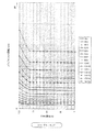
次に、自動変速制御の内容を説明する。TMCU9には図5に示すシフトアップマップと図6に示すシフトダウンマップとがメモリされており、TMCU9は、自動変速モードのとき、これらマップに従って自動変速を実行する。例えば図5のシフトアップマップにおいて、ギヤ段n(nは1から15までの整数)からn+1へのシフトアップ線図がアクセル開度(%)と出力軸回転数(rpm )との関数で決められている。そしてマップ上では現在のアクセル開度(%)と出力軸回転数(rpm )とからただ1点が定まる。車両加速中は、車輪に連結された出力軸4の回転数が次第に増加していく。そこで通常の自動変速モードでは、現在の1点が各線図を越える度に1段ずつシフトアップを行うこととなる。このときスキップモードであれば線図を交互に1本ずつ飛ばして2段ずつシフトアップを行う。
【0044】
図6のシフトダウンマップにおいても同様に、ギヤ段n+1(nは1から15までの整数)からnへのシフトダウン線図がアクセル開度(%)と出力軸回転数(rpm )との関数で決められている。そしてマップ上では現在のアクセル開度 (%)と出力軸回転数(rpm )とからただ1点が定まる。車両減速中は出力軸4の回転数が次第に減少していくので、通常の自動変速モードでは、現在の1点が各線図を越える度に1段ずつシフトダウンを行う。スキップモードであれば線図を交互に1本ずつ飛ばして2段ずつシフトダウンする。
【0045】
一方、マニュアルモードのときは、これらマップと無関係にドライバが自由にシフトアップ・ダウンを行える。通常モードなら1回のシフトチェンジ操作で1段変速でき、スキップモードなら1回のシフトチェンジ操作で2段変速できる。
【0046】
現在のアクセル開度はアクセル開度センサ8により検知され、現在の出力軸回転数は出力軸回転センサ28により検知される。特に、TMCU9は、現在の出力軸回転数の値から現在の車速を換算し、これをスピードメータに表示する。つまり車速が出力軸回転数から間接的に検知され、出力軸回転数と車速とは比例関係にある。
【0047】
次に、本発明に係るエンスト防止及びクラッチ保護制御について説明する。ここではドライバが車両をマニュアルモードで走行中、現ギヤ段を保持しつつフットブレーキ等で車両を減速し、ある瞬間アクセルを踏み込んで再加速しようとした場合を想定している。減速の過程でエンジン回転数がアイドリング回転付近まで落ちると、エンストの虞があるためクラッチが自動分断され、次回再加速時にアクセルが踏み込まれるまでクラッチが断状態に保持される。しかし、この高いギヤのままアクセルが踏み込まれ、クラッチを再接続したのでは、ギヤが高すぎてエンストしたりクラッチが過剰に滑ったりする問題が生じる。本制御はこのような事態を防止し、アクセルが踏み込まれたときは、手動シフトスイッチからの変速指示信号にかかわらず、つまりドライバが何等シフトチェンジ操作をせず現ギヤ段を保持しても、クラッチ接続前にギヤを適正なギヤまで自動的にシフトダウンし、それからクラッチを接続しようというものである。
【0048】
図1に示すように、TMCU9はまずステップ101でモードスイッチ24の出力から現在マニュアルモードか否かを判断する。マニュアルモードのときはステップ102に進み、マニュアルモードでないときENDに進む。これは再加速時のエンスト及びクラッチ過剰滑りはマニュアルモードのときにのみ起こり得るからである。自動モードのときは車速に応じて自動的にシフトダウンされるので上記の問題は生じない。スキップモードであるか否かは問わない。
【0049】
ステップ102では、現在シフトレバーの位置がD(マニュアルモードなのでH)か否かをシフトレバー装置29の信号に基づいて判断する。本制御を行う条件としてドライバがシフトチェンジ操作してないことが必要だからである。Dならステップ103に進む。DでなければENDに進み、変速完了待ちとなる。
【0050】
ステップ103では、入力軸15の回転数(クラッチ回転数ともいう)が所定値(ここでは450(rpm))未満か否かを判断する。所定値以上と判断したときはステップ111に進む。ステップ111では現在のギヤ段(現ギヤ段)を次回の変速先である目標ギヤ段とし、結局変速は行わない。所定値未満と判断したときはステップ104に進む。エンジンのアイドリング回転数が500(rpm)に設定されているので、入力軸回転数がそれより若干低い450(rpm)を下回ったならば本制御を行うようにしている。このときはクラッチが確実に切られているからである。また、それ程回転が落ちてないのに勝手に(自動で)シフトダウンしてしまうと、必ずしもドライバの意思に沿わないときがあるからである。もっとも、減速過程で実際にクラッチが切られるのは入力軸回転数がアイドリング回転数より若干高い値、例えば900(rpm)になったときである。このように本制御はアイドリング回転数付近でクラッチ断が実行されるものについて行われる。
【0051】
入力軸回転数は、カウンタシャフト回転センサ26により検知されるカウンタシャフト回転数から換算する。即ち、TMCU9は変速機内の各ギヤ歯数及び各ギヤ組のギヤ比を記憶しており、入力軸回転数N1 を、カウンタシャフト回転数N2 と、スプリットハイギヤSH(インプットギヤともいう)の歯数Z1 と、カウンタギヤCH(インプットカウンタギヤともいう)の歯数Z2 とから次式により求める。
【0052】
N1 =(Z2 /Z1 )×N2
ステップ104では、アクセル開度センサ8の出力から、現在のアクセル開度が所定値(ここでは5(%) )を上回っているか否かを判断する。即ち、このようにアクセルが所定値を越えて踏み込まれると、加速の意思有りと判断してクラッチが自動接続されるからである。アクセル開度が所定値を上回っていればステップ105に進み、アクセル開度が所定値以下であればステップ111に進む。
【0053】
ステップ105では、クラッチストロークセンサ14の出力から、現在クラッチが実際に分断されているか否かを判断する。これはステップ103でクラッチ断と判断されても、他の制御との干渉により、或いは何らかの異常により、クラッチが実際に分断されていないこともあり得るため、念のため本ステップを追加したものである。クラッチ断と判断したときはステップ106に進み、クラッチ断でないと判断したときはステップ111に進む。
【0054】
ステップ106では、ギヤポジションスイッチ23により検知される現在のギヤ段(現ギヤ段)を、予め設定されTMCU9内に記憶された発進ギヤ段(例えば4速又は9速)と比較し、現ギヤ段が発進ギヤ段より高いか否かを判断する。これは、現ギヤ段が発進ギヤ段より低い場合は、車両の減速に際しドライバが自らの意思で低めにシフトダウンしたことを意味するので、このようなときは本制御を行わないようにするためである。よって現ギヤ段が発進ギヤ段以下の場合はステップ111に進み、現ギヤ段が発進ギヤ段より大きい場合は次のステップ107に進む。
【0055】
ステップ107では、アクセル開度センサ8により検知される現在のアクセル開度と、出力軸回転センサ28により検知される現在の出力軸回転数とから、図5のシフトアップマップに従って現在の最適ギヤ段を選択する。そしてステップ108で、選択された最適ギヤ段と上記発進ギヤ段とを比較する。最適ギヤ段が発進ギヤ段より低いと判断したときはステップ109に進んで発進ギヤ段を目標ギヤ段とする。最適ギヤ段が発進ギヤ段以上と判断したときはステップ110に進んで最適ギヤ段を目標ギヤ段とする。このようにいずれか高い方のギヤ段を目標ギヤ段とする。
【0056】
こうして目標ギヤ段の決定を終えたら、その目標ギヤ段に変速機を自動変速する。これにより適度なシフトダウンが行われ、その後クラッチが自動接続され再加速可能となる。
【0057】
本制御によれば、再加速しようとしてアクセルを踏み込んでも、車両の走行状態に適したギヤ段まで自動的にシフトダウンされてからクラッチが接続されるので、クラッチが接続された瞬間エンストしたり、クラッチが過剰に滑ったりすることがない。これにより運転フィーリングが向上し、クラッチも保護され耐久性が向上する。
【0058】
最適ギヤ段と発進ギヤ段とのうちいずれか高い方のギヤ段を目標ギヤ段とするのは、少なくとも発進ギヤ段より高いギヤ段を次回の変速先とするためである。即ち、例えば高速ギヤ段のまま極低速まで車両を減速した場合、シフトアップマップに従えば発進ギヤ段より低いギヤ段(例えば1速又は2速)までシフトダウンされる可能性があり、こうなるとクラッチが再接続されたときに接続ショックが生じたり、エンジンが急激に吹け上ったりしてフィーリングが悪化するからである。そこでこのような事態を防止するため、少なくとも発進ギヤ段より高いギヤ段を選択するようにした。また再加速のときある程度車速が出ている場合は発進ギヤ段では低すぎることがあるので、このようなときはマップから選択した最適ギヤ段を変速先とし、フィーリングの向上を図るようにした。
【0059】
以上、本発明の実施形態は上述のものに限られない。最適ギヤ段は必ずしもアクセル開度と出力軸回転数とから決定する必要はない。出力軸回転数の代わりに車速を用いてもよい。マップも上述のようなシフトアップマップに限らない。手動シフトスイッチも、例えばステアリングホイールに設けたスイッチのようなものが可能である。
【0060】
【発明の効果】
本発明は次の如き優れた効果を発揮する。
【0061】
(1) 車両減速後再加速時のエンストやクラッチ滑りを防止できる。
【0062】
(2) 運転フィーリングを向上できる。
【図面の簡単な説明】
【図1】本発明に係るエンスト及びクラッチ過剰滑り防止制御の内容を示すフローチャートである。
【図2】実施形態に係る車両のエンジン駆動系を示す構成図である。
【図3】自動変速機を示す構成図である。
【図4】自動クラッチ装置を示す構成図である。
【図5】シフトアップマップである。
【図6】シフトダウンマップである。
【符号の説明】
1 エンジン
2 クラッチ
3 変速機
7 エンジン回転センサ
8 アクセル開度センサ
9 トランスミッションコントロールユニット(TMCU)
10 クラッチブースタ
20 スプリッタアクチュエータ
21 メインアクチュエータ
22 レンジアクチュエータ
26 カウンタシャフト回転センサ
28 出力軸回転センサ
29 シフトレバー装置
29a シフトレバー
GSU ギヤシフトユニット[0001]
BACKGROUND OF THE INVENTION
The present invention relates to a speed change apparatus for a vehicle that is particularly applicable to large vehicles such as a tractor.
[0002]
[Prior art]
Recently, in order to reduce the burden on the driver, there are many examples of adopting an automatic clutch device and an automatic transmission even in a large vehicle such as a tractor and a truck. In this case, the optimum gear stage corresponding to the vehicle speed is determined according to the map, and upshifting / downshifting is automatically performed according to acceleration / deceleration of the vehicle.
[0003]
On the other hand, even in such an automatic transmission device, there is one that can be manually shifted by a driver's shift change operation. This is a so-called manual mode. In this case, if the driver does not perform a shift change operation, the current gear stage is held (held), and only when the driver performs a shift change operation, the up / down operation can be performed.
[0004]
Such an automatic transmission generally includes an automatic clutch device that automatically connects and disconnects a friction clutch with an actuator.
[0005]
[Problems to be solved by the invention]
By the way, the manual mode has the following problems. That is, for example, when the vehicle is decelerated to a low speed while holding the gear on the relatively high speed side, the clutch is automatically disengaged because the engine may be stalled, and the disengaged state is maintained. The clutch is automatically connected the moment you depress the accelerator to re-accelerate. However, since the gear remains at a high speed, there is a problem that the engine stalls at the moment when the clutch is connected or the clutch slips excessively. This hinders smooth operation and is not good from the viewpoint of clutch protection.
[0006]
Therefore, an object of the present invention is to prevent engine stall and protect a clutch when the vehicle is reaccelerated after deceleration in the manual mode.
[0007]
[Means for Solving the Problems]
The present invention includes a manual shift mode for speed change of the transmission according to a shift instruction signal from the manual shift switch, the automatic shift mode to the automatic shift the transmission according to the current vehicle operating conditions, in the manual shift mode a speed change apparatus for a vehicle and a control means for connect the clutch when and accelerator opening in a clutch disconnection state divide the clutch during the shift exceeds a predetermined value, said control means, said manual in shift mode, when the input shaft rotation speed of the transmission falls below a predetermined value in the vicinity of idling speed of the engine, to divide the clutch, when the accelerator opening is Tsu exceeded a predetermined value in a clutch disengaged state, the current any higher of the optimum gear with a preset starting gear position is selected according to the vehicle driving state and target gear, varying from the manual shift switch Regardless of instruction signals, it is also to to connect the clutch after the shift to the target gear.
[0008]
Here, it is preferable that the optimum gear is selected according to a map from the current accelerator opening and the output shaft speed of the transmission.
[0009]
The manual shift switch is preferably operated based on the operation of the shift lever.
[0010]
Further, in the manual shift mode, when the input shaft rotational speed of the transmission falls below a predetermined value near the idle rotational speed of the engine, the control means operates the manual shift switch by the driver in a clutch disengaged state. When shifting down to the gear position below the starting gear stage according to the shift instruction signal from the manual shift switch, the shift to the target gear stage is performed when the accelerator opening exceeds a predetermined value in the clutch disengaged state. not to, preferably to connect the clutch remains gear shifted down.
[0011]
DETAILED DESCRIPTION OF THE INVENTION
Preferred embodiments of the present invention will be described below in detail with reference to the accompanying drawings.
[0012]
FIG. 2 shows a transmission ( automatic transmission ) for a vehicle according to this embodiment. Here, the vehicle is a tractor that pulls the trailer, and the engine is a diesel engine. As shown in the figure, a transmission 3 is attached to the
[0013]
As shown in FIG. 3, the flywheel 1b is attached to the crankshaft of the engine, the ring gear 1c is formed on the outer periphery of the flywheel 1b, and the
[0014]
As shown in FIG. 2, here, the
[0015]
As shown in FIGS. 2, 3, and 4, the
[0016]
As clearly shown in FIG. 4, the
[0017]
The solenoid valves MVC1, MVC2, and MVCE are ON / OFF controlled by the
[0018]
However, if an abnormality occurs in the electromagnetic valve MVC1 or MVC2 during clutch disconnection and either of them is turned OFF, the clutch is suddenly engaged against the driver's intention. Therefore, when such an abnormality is detected by the abnormality diagnosis circuit of the
[0019]
Next, the manual side will be described. The hydraulic pressure is supplied / discharged from the master cylinder 13 in response to the depression / return operation of the
[0020]
As shown in detail in FIG. 3, the transmission 3 is basically a so-called multi-stage transmission that is always meshed, and can shift to 16 forward speeds and 2 reverse speeds. The transmission 3 includes a
[0021]
A gear shift unit GSU is provided to automatically shift the transmission 3, and is composed of a
[0022]
In this automatic transmission, a manual mode is set, and a manual shift based on a driver's shift change operation is possible. In this case, as shown in FIG. 2, the connection / disconnection control of the
[0023]
In the shift lever device 29, R means reverse, N means neutral, D means drive, UP means shift up, and DOWN means shift down. The driver's seat is provided with a
[0024]
If the shift lever 29a is put in the D range in the automatic shift mode, the shift is automatically performed according to the vehicle speed. Even in the automatic transmission mode, if the driver operates the shift lever 29a to UP or DOWN, manual upshifting or downshifting is possible. In this automatic shift mode, if the
[0025]
On the other hand, in the manual shift mode, the shift completely follows the driver's intention. When the shift lever 29a is in the D range, no speed change is performed, and the current gear is held, and the shift up or down is possible only when the shift lever 29a is operated to UP or DOWN with the driver's positive intention. At this time, similarly to the above, if the
[0026]
An
[0027]
As shown in FIG. 3, in the transmission 3, the input shaft 15, the
[0028]
First, the configuration of the
[0029]
Each of the gears SH, M4,... Attached to the input shaft 15 and the
[0030]
As described above, the
[0031]
Next, the configuration of the range gear 19 will be described. The range gear 19 employs a planetary gear mechanism 34 and can be switched to either a high or low position. The planetary gear mechanism 34 includes a
[0032]
The fifth spline 41 is provided integrally with the pipe portion 69. An output shaft spline 70 is integrally provided on the
[0033]
When the fifth sleeve 46 moves forward, it engages with the fixed
[0034]
On the other hand, when the fifth sleeve 46 moves rearward, it engages with the output shaft spline 70, and the fifth spline 41 and the output shaft spline 70 are connected. As a result, the ring gear 67 and the carrier 68 are fixed to each other, and the
[0035]
In this way, in this transmission 3, on the forward side, it is possible to shift to two stages of high and low by the
[0036]
Next, each actuator 20, 21, 22 will be described. These actuators are composed of a pneumatic cylinder that is operated by the air pressure of the
[0037]
The
[0038]
The main actuator 21 includes a pneumatic cylinder 48 having a double piston and responsible for the operation on the select side, and a pneumatic cylinder 49 having a single piston and responsible for the operation on the shift side. Three solenoid valves MVC, MVD, MVE and MVB, MVA are provided for each pneumatic cylinder.
[0039]
The select-side pneumatic cylinder 48 moves downward in the figure when MVC / OFF, MVD / ON, and MVE / OFF, and can select 3rd, 4th, or N3 of the main gear, and MVC / ON, MVD / OFF, MVE / When ON, it becomes neutral, and the 1st, 2nd or N2 of the main gear can be selected, and when it is MVC / ON, MVD / OFF, or MVE / OFF, it moves upward in the figure, and the main gear Rev or N1 can be selected.
[0040]
The shift-side pneumatic cylinder 49 is neutral when MVA / ON or MVB / ON, and can select N1, N2 or N3 of the main gear, and moves to the left side of the figure when MVA / ON or MVB / OFF. 2nd, 4th or Rev can be selected, and when MVA / OFF or MVB / ON, it moves to the right side of the figure, and 1st or 3rd of the main gear can be selected.
[0041]
The range actuator 21 includes a
[0042]
Incidentally, a
[0043]
Next, the contents of the automatic shift control will be described. The
[0044]
Similarly, in the shift-down map of FIG. 6, the shift-down diagram from the gear stage n + 1 (n is an integer from 1 to 15) to n is a function of the accelerator opening (%) and the output shaft speed (rpm). It is decided by. On the map, only one point is determined from the current accelerator opening (%) and output shaft speed (rpm). Since the rotation speed of the
[0045]
On the other hand, in manual mode, the driver can freely shift up and down regardless of these maps. In the normal mode, one shift can be achieved by one shift change operation, and in the skip mode, two shifts can be achieved by one shift change operation.
[0046]
The current accelerator opening is detected by the accelerator opening sensor 8, and the current output shaft rotation speed is detected by the output
[0047]
Next, engine stall prevention and clutch protection control according to the present invention will be described. Here, it is assumed that the driver decelerates the vehicle with a foot brake or the like while holding the current gear while driving the vehicle in the manual mode, and depresses the accelerator for a certain moment to re-accelerate. If the engine speed drops to near the idling speed in the deceleration process, there is a possibility of engine stall, so the clutch is automatically disconnected, and the clutch is held in the disconnected state until the accelerator is depressed at the next re-acceleration. However, if the accelerator is depressed with this high gear and the clutch is reconnected, there is a problem that the gear is too high and the engine stalls or the clutch slips excessively. This control prevents such a situation, and when the accelerator is depressed, regardless of the shift instruction signal from the manual shift switch, that is, even if the driver does not perform any shift change operation and maintains the current gear stage , The gear is automatically shifted down to the proper gear before the clutch is connected, and then the clutch is connected.
[0048]
As shown in FIG. 1, the
[0049]
In
[0050]
In
[0051]
The input shaft rotation speed is converted from the counter shaft rotation speed detected by the counter
[0052]
N 1 = (Z 2 / Z 1 ) × N 2
In
[0053]
In step 105, it is determined from the output of the clutch stroke sensor 14 whether or not the current clutch is actually disconnected. Even if it is determined in
[0054]
In
[0055]
In
[0056]
When the determination of the target gear stage is thus completed, the transmission is automatically shifted to the target gear stage. As a result, a moderate downshift is performed, and then the clutch is automatically connected to enable reacceleration.
[0057]
According to this control, even if the accelerator is depressed to re-accelerate, the clutch is connected after being automatically shifted down to the gear stage suitable for the running state of the vehicle. The clutch will not slip excessively. This improves driving feeling, protects the clutch, and improves durability.
[0058]
The reason why the higher gear stage between the optimum gear stage and the starting gear stage is set as the target gear stage is that at least a gear stage higher than the starting gear stage is set as the next shift destination. That is, for example, when the vehicle is decelerated to an extremely low speed while maintaining a high gear, there is a possibility that the vehicle may be shifted down to a gear lower than the starting gear (for example, first gear or second gear) according to the shift-up map. This is because when the clutch is reconnected, a connection shock occurs, or the engine suddenly blows up to deteriorate the feeling. Therefore, in order to prevent such a situation, at least a gear higher than the starting gear is selected. Also, if the vehicle speed is somewhat high at the time of re-acceleration, the starting gear stage may be too low. In such a case, the optimum gear stage selected from the map is used as the shift destination to improve the feeling. .
[0059]
As mentioned above, embodiment of this invention is not restricted to the above-mentioned thing. The optimum gear stage is not necessarily determined from the accelerator opening and the output shaft rotational speed. The vehicle speed may be used instead of the output shaft speed. The map is not limited to the shift-up map as described above. The manual shift switch can also be a switch provided on the steering wheel, for example.
[0060]
【The invention's effect】
The present invention exhibits the following excellent effects.
[0061]
(1) Engine stall and clutch slippage during re-acceleration after vehicle deceleration can be prevented.
[0062]
(2) Driving feeling can be improved.
[Brief description of the drawings]
FIG. 1 is a flowchart showing the contents of engine stall and clutch excessive slip prevention control according to the present invention.
FIG. 2 is a configuration diagram showing an engine drive system of the vehicle according to the embodiment.
FIG. 3 is a configuration diagram showing an automatic transmission.
FIG. 4 is a configuration diagram showing an automatic clutch device.
FIG. 5 is a shift-up map.
FIG. 6 is a shift down map.
[Explanation of symbols]
1
10
Claims (4)
上記制御手段は、
上記マニュアル変速モードにおいて、
変速機の入力軸回転数がエンジンのアイドリング回転数付近の所定値を下回ったとき、クラッチを分断し、
クラッチ断状態でアクセル開度が所定値を上回ったとき、現在の車両運転状態に応じて選択される最適ギヤ段と予め設定された発進ギヤ段とのうちいずれか高い方を目標ギヤ段とし、上記手動シフトスイッチからの変速指示信号にかかわらず、上記目標ギヤ段に変速してからクラッチを接続することを特徴とする車両の変速装置。 And a manual shift mode for speed change of the transmission according to a shift instruction signal from the manual shift switch, the automatic shift mode to the automatic shift the transmission according to the current vehicle operating conditions, at the time of shifting in the manual shift mode a speed change apparatus for a vehicle and a control means for connect the clutch when and accelerator opening in a clutch disconnection state disrupt the clutch exceeds a predetermined value,
The control means includes
In the manual shift mode,
When the input shaft speed of the transmission falls below a predetermined value near the engine idling speed, the clutch is disconnected,
When the accelerator opening in the clutch disengaged state is Tsu exceeded a predetermined value, the target gear of the higher one of the best gear to be selected depending on the current vehicle operating conditions with a preset starting gear and then, regardless of the shift instruction signal from the manual shift switch, speed change device for a vehicle according to claim and Turkey connecting the clutch after the shift to the target gear.
上記マニュアル変速モードにおいて、
変速機の入力軸回転数がエンジンのアイドル回転数付近の所定値を下回ったとき、クラッチ断状態でドライバにより上記手動シフトスイッチが操作されて、上記手動シフトスイッチからの変速指示信号に従って上記発進ギヤ段以下のギヤ段にシフトダウンした場合には、
クラッチ断状態でアクセル開度が所定値を上回ったとき、上記目標ギヤ段への変速を行わずに、シフトダウンしたギヤ段のままでクラッチを接続する請求項1から3いずれかに記載の車両の変速装置。The control means includes
In the manual shift mode,
When the input shaft rotational speed of the transmission falls below a predetermined value near the engine idle rotational speed, the manual shift switch is operated by the driver in a clutch disengaged state, and the start gear is in accordance with a shift instruction signal from the manual shift switch. If you shift down to a gear below
The vehicle according to any one of claims 1 to 3 , wherein when the accelerator opening degree exceeds a predetermined value in a clutch disengaged state, the clutch is connected without changing the gear to the target gear without changing the gear. change speed device.
Priority Applications (4)
| Application Number | Priority Date | Filing Date | Title |
|---|---|---|---|
| JP2000076370A JP4092846B2 (en) | 2000-03-14 | 2000-03-14 | Vehicle transmission |
| DE60104461T DE60104461T2 (en) | 2000-03-14 | 2001-03-05 | Control for automatic vehicle transmissions |
| EP01105507A EP1134111B1 (en) | 2000-03-14 | 2001-03-05 | Control system for automatic vehicle transmissions |
| US09/802,042 US6415214B2 (en) | 2000-03-14 | 2001-03-08 | Automatic transmission of vehicle |
Applications Claiming Priority (1)
| Application Number | Priority Date | Filing Date | Title |
|---|---|---|---|
| JP2000076370A JP4092846B2 (en) | 2000-03-14 | 2000-03-14 | Vehicle transmission |
Publications (2)
| Publication Number | Publication Date |
|---|---|
| JP2001260714A JP2001260714A (en) | 2001-09-26 |
| JP4092846B2 true JP4092846B2 (en) | 2008-05-28 |
Family
ID=18594127
Family Applications (1)
| Application Number | Title | Priority Date | Filing Date |
|---|---|---|---|
| JP2000076370A Expired - Fee Related JP4092846B2 (en) | 2000-03-14 | 2000-03-14 | Vehicle transmission |
Country Status (4)
| Country | Link |
|---|---|
| US (1) | US6415214B2 (en) |
| EP (1) | EP1134111B1 (en) |
| JP (1) | JP4092846B2 (en) |
| DE (1) | DE60104461T2 (en) |
Families Citing this family (18)
| Publication number | Priority date | Publication date | Assignee | Title |
|---|---|---|---|---|
| US6558293B2 (en) * | 2001-06-11 | 2003-05-06 | General Motors Corporation | Garage shift control for a motor vehicle automatic transmission |
| DE10334930A1 (en) * | 2003-07-31 | 2005-02-24 | Zf Friedrichshafen Ag | Operating method for vehicle automatic transmission, ending shift-in with open clutch when speed is below limit value |
| US6935204B2 (en) | 2003-10-31 | 2005-08-30 | Caterpillar Inc | Automated manual transmission and shift method |
| JP5137375B2 (en) * | 2006-09-29 | 2013-02-06 | 本田技研工業株式会社 | Control method of power transmission device |
| JP4306713B2 (en) * | 2006-10-20 | 2009-08-05 | トヨタ自動車株式会社 | VEHICLE CONTROL DEVICE, CONTROL METHOD, PROGRAM FOR IMPLEMENTING THE CONTROL METHOD BY COMPUTER AND RECORDING MEDIUM CONTAINING THE PROGRAM |
| DE102007010295B4 (en) * | 2007-03-02 | 2020-09-03 | Zf Friedrichshafen Ag | Method for controlling a drive train of a motor vehicle |
| DE102007012875A1 (en) | 2007-03-17 | 2008-09-18 | Zf Friedrichshafen Ag | Method for operating an automatic transmission |
| DE102007024363A1 (en) * | 2007-05-24 | 2008-11-27 | Zf Friedrichshafen Ag | Method for controlling a drive train of a motor vehicle |
| JP5251484B2 (en) * | 2008-12-19 | 2013-07-31 | 日産自動車株式会社 | Control device for hybrid vehicle |
| JP5620671B2 (en) * | 2009-11-24 | 2014-11-05 | ヤマハ発動機株式会社 | Transmission |
| SE534650C2 (en) | 2010-02-01 | 2011-11-08 | Scania Cv Ab | Procedure and system for controlling a gearbox |
| EP2397921B1 (en) * | 2010-06-17 | 2017-08-30 | Blancpain S.A. | Mechanism for a jumping tourbillon cage |
| US9404570B2 (en) * | 2011-12-15 | 2016-08-02 | Renault Trucks | Control method for an automated gearbox of an automotive vehicle, system for controlling such a gearbox and automotive vehicle equipped with such a system |
| DE102013214241A1 (en) * | 2013-07-22 | 2015-01-22 | Bayerische Motoren Werke Aktiengesellschaft | Device for optimizing the gear change control for an automatic transmission in a motor vehicle |
| DE102013013154A1 (en) * | 2013-08-08 | 2015-02-12 | Frank Ropertz | Double clutch |
| JP5702840B2 (en) * | 2013-09-09 | 2015-04-15 | ヤマハ発動機株式会社 | Transmission |
| JP2016005929A (en) * | 2014-06-20 | 2016-01-14 | トヨタ自動車株式会社 | Vehicular control apparatus |
| DE102014019127B4 (en) * | 2014-12-19 | 2016-11-03 | Audi Ag | Method for operating a transmission device for a motor vehicle and corresponding transmission device |
Family Cites Families (6)
| Publication number | Priority date | Publication date | Assignee | Title |
|---|---|---|---|---|
| US5157608A (en) * | 1990-09-14 | 1992-10-20 | Ford Motor Company | Electronic control system for multiple ratio transmission including circuit pressure control |
| JP3129126B2 (en) * | 1994-12-09 | 2001-01-29 | 三菱自動車工業株式会社 | Shift control method for electric vehicle |
| JPH0988651A (en) * | 1995-09-29 | 1997-03-31 | Toyota Motor Corp | Engine braking force control device |
| US5984828A (en) * | 1998-03-16 | 1999-11-16 | Meritor Heavy Vehicle Systems, Llc | Control methods for a shift by wire vehicle transmission |
| JP3297999B2 (en) | 1998-05-12 | 2002-07-02 | 住友金属工業株式会社 | Mandrel mill rolling equipment and rolling method used therefor |
| DE19921920B4 (en) * | 1999-05-12 | 2005-11-17 | Zf Sachs Ag | Method for protecting a friction clutch |
-
2000
- 2000-03-14 JP JP2000076370A patent/JP4092846B2/en not_active Expired - Fee Related
-
2001
- 2001-03-05 EP EP01105507A patent/EP1134111B1/en not_active Expired - Lifetime
- 2001-03-05 DE DE60104461T patent/DE60104461T2/en not_active Expired - Lifetime
- 2001-03-08 US US09/802,042 patent/US6415214B2/en not_active Expired - Fee Related
Also Published As
| Publication number | Publication date |
|---|---|
| US20010023385A1 (en) | 2001-09-20 |
| DE60104461T2 (en) | 2005-08-18 |
| EP1134111B1 (en) | 2004-07-28 |
| EP1134111A2 (en) | 2001-09-19 |
| DE60104461D1 (en) | 2004-09-02 |
| US6415214B2 (en) | 2002-07-02 |
| EP1134111A3 (en) | 2002-06-19 |
| JP2001260714A (en) | 2001-09-26 |
Similar Documents
| Publication | Publication Date | Title |
|---|---|---|
| JP3945118B2 (en) | Control device for selective clutch | |
| JP4092846B2 (en) | Vehicle transmission | |
| JP4663840B2 (en) | Engine overrun prevention device for automatic transmission | |
| JP4515592B2 (en) | Automatic transmission for vehicle | |
| JP2001280463A (en) | Automatic transmission for vehicle | |
| JP4140188B2 (en) | Automatic transmission for vehicle | |
| JP4284820B2 (en) | Automatic transmission for vehicle | |
| JP4100057B2 (en) | Shift control device | |
| JP4343415B2 (en) | Automatic transmission for vehicle | |
| JP4415291B2 (en) | Automatic transmission for vehicle | |
| JP4470272B2 (en) | Automatic transmission for vehicle | |
| JP3893842B2 (en) | Vehicle auto clutch control device | |
| JP4078783B2 (en) | Automatic clutch device for vehicle | |
| JP4637996B2 (en) | Automatic transmission for vehicle | |
| JP4426051B2 (en) | Automatic transmission for vehicle | |
| JP4470919B2 (en) | Vehicle auto clutch control device | |
| JP3888150B2 (en) | Shift control device | |
| JP4284825B2 (en) | Automatic transmission for vehicle | |
| JP4221957B2 (en) | Shift control device | |
| JP4366902B2 (en) | Shift control device | |
| JP4411826B2 (en) | Shift control device | |
| JP3888153B2 (en) | Vehicle slope start assist device | |
| JP4505935B2 (en) | Automatic transmission for vehicle | |
| JP4581178B2 (en) | Automatic transmission for vehicle | |
| JP4239359B2 (en) | Automatic transmission for vehicle |
Legal Events
| Date | Code | Title | Description |
|---|---|---|---|
| A621 | Written request for application examination |
Free format text: JAPANESE INTERMEDIATE CODE: A621 Effective date: 20051129 |
|
| A131 | Notification of reasons for refusal |
Free format text: JAPANESE INTERMEDIATE CODE: A131 Effective date: 20070918 |
|
| A521 | Request for written amendment filed |
Free format text: JAPANESE INTERMEDIATE CODE: A523 Effective date: 20071108 |
|
| TRDD | Decision of grant or rejection written | ||
| A01 | Written decision to grant a patent or to grant a registration (utility model) |
Free format text: JAPANESE INTERMEDIATE CODE: A01 Effective date: 20080212 |
|
| A61 | First payment of annual fees (during grant procedure) |
Free format text: JAPANESE INTERMEDIATE CODE: A61 Effective date: 20080225 |
|
| FPAY | Renewal fee payment (event date is renewal date of database) |
Free format text: PAYMENT UNTIL: 20110314 Year of fee payment: 3 |
|
| R150 | Certificate of patent or registration of utility model |
Free format text: JAPANESE INTERMEDIATE CODE: R150 |
|
| FPAY | Renewal fee payment (event date is renewal date of database) |
Free format text: PAYMENT UNTIL: 20120314 Year of fee payment: 4 |
|
| FPAY | Renewal fee payment (event date is renewal date of database) |
Free format text: PAYMENT UNTIL: 20120314 Year of fee payment: 4 |
|
| FPAY | Renewal fee payment (event date is renewal date of database) |
Free format text: PAYMENT UNTIL: 20130314 Year of fee payment: 5 |
|
| FPAY | Renewal fee payment (event date is renewal date of database) |
Free format text: PAYMENT UNTIL: 20130314 Year of fee payment: 5 |
|
| FPAY | Renewal fee payment (event date is renewal date of database) |
Free format text: PAYMENT UNTIL: 20140314 Year of fee payment: 6 |
|
| LAPS | Cancellation because of no payment of annual fees |