EP1178234B1 - Clutch arrangement - Google Patents
Clutch arrangement Download PDFInfo
- Publication number
- EP1178234B1 EP1178234B1 EP01115617A EP01115617A EP1178234B1 EP 1178234 B1 EP1178234 B1 EP 1178234B1 EP 01115617 A EP01115617 A EP 01115617A EP 01115617 A EP01115617 A EP 01115617A EP 1178234 B1 EP1178234 B1 EP 1178234B1
- Authority
- EP
- European Patent Office
- Prior art keywords
- clutch
- torque
- gear
- drive shaft
- planetary gear
- Prior art date
- Legal status (The legal status is an assumption and is not a legal conclusion. Google has not performed a legal analysis and makes no representation as to the accuracy of the status listed.)
- Expired - Lifetime
Links
Images


Classifications
-
- F—MECHANICAL ENGINEERING; LIGHTING; HEATING; WEAPONS; BLASTING
- F16—ENGINEERING ELEMENTS AND UNITS; GENERAL MEASURES FOR PRODUCING AND MAINTAINING EFFECTIVE FUNCTIONING OF MACHINES OR INSTALLATIONS; THERMAL INSULATION IN GENERAL
- F16D—COUPLINGS FOR TRANSMITTING ROTATION; CLUTCHES; BRAKES
- F16D28/00—Electrically-actuated clutches
Definitions
- the present invention relates to a clutch assembly for transmitting a torque from an input shaft to an output shaft according to the preamble of Patent claim 1.
- a clutch assembly is made DE-C-97291 known.
- the power transmission takes place from the engine to the transmission, for example via a switchable friction clutch.
- This friction clutch allows the adhesion during a gear change to interrupt.
- friction clutches are usually two discs compressed to enter through the frictional contact To transmit torque.
- the control of torque occurs e.g. about the distance of Clutch discs.
- the actuation of the coupling can mechanically, hydraulically or electro-hydraulically.
- automated manual transmissions which e.g. be electro-hydraulically actuated.
- an adjusting device for a friction clutch which the Compensates wear occurring in friction clutches, without the need for additional space.
- the actuator on a separate drive, the via an output device with the friction clutch in Active compound can be brought.
- the output device provided with a compensation device to a wear-related change in position of the pressure spring of To compensate for friction clutch.
- the coupling arrangement according to the invention with the features of claim 1 has the advantage that they have an actuating device for engagement and / or disengagement the coupling elements used, wherein the adjusting device is directly connected to a drive shaft and whose Rotational energy directly to the position of the coupling elements used.
- This is the actuation of the clutch assembly necessary job energy for the actuator directly from the drive train or drive shaft removable.
- an actuation of the Coupling arrangement on the adjusting device from the Powertrain removed energy not only to drive an electric motor, an electromagnet or a Hydraulic cylinder as used in the prior art but the energy of the powertrain becomes directly, i. without conversion, the actuator supplied to actuate the clutch assembly. Consequently are according to the invention no additional facilities for Driving the adjusting device necessary. This results Significant cost advantages.
- the adjusting device at least one helical gear on.
- the gear is as helical teeth Double planetary gear formed.
- the two can Planetary wheels which lie on a common axis have a different number of teeth.
- the planetary gear is a planetary gear between arranged the drive shaft and the adjusting device.
- the planetary gear as Wolform planetary gear formed, in which two planetary gear are connected in series with a common ring gear.
- the Actuator preferably a spring element.
- the spring element has the task of the travel to assign a certain contact force.
- the actuator of the clutch assembly is as Brake or designed as an electric motor.
- the brake can rotatably with a sun gear of the planetary gear be connected and can, for example, as Eddy current brake be formed. Through this brake can the torque on the sun gear can be determined and thereby the applied to the ring gear of the planetary gear Torque be determined.
- the invention Coupling arrangement designed as a double clutch. at Double clutches must be under load from one to the other Coupling can be switched. This can be done with the invention Coupling arrangement without interruption of traction and done without distortion of the transmission. Of the Umkuppelvorgang from one clutch to the other clutch can thus only by a torque-based control of Coupling can be achieved, reducing the Umkuppelvorgang is greatly simplified.
- the planetary gear has a control input on which it is connected to the actuator.
- the set input can be a setpoint for the to be transmitted Torque by specifying a twist angle of a Clutch disc can be adjusted.
- an adjusting device which provides the rotational energy of the Drive shaft without energy conversion directly to Engaging and / or disengaging the coupling elements used.
- This can be on expensive drive elements for Make the coupling elements are omitted. Further This can cause loss due to energy conversion of the Rotational energy in e.g. hydraulic pressure energy be avoided. This allows the overall efficiency of the Motor vehicle can be increased. Thus, a special space-saving coupling arrangement can be provided.
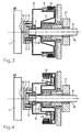
- FIG. 1 and 2 is a clutch assembly shown.
- This coupling arrangement can, for example be used in a dual-clutch transmission, in which the power flow alternately via one of two-transmission branches is directed.
- the clutch assembly comprises an electric motor 1, which via a shaft 14 with a Ring gear 2 is connected.
- the ring gear 2 is part of a Wolform planetary gear, which further planetary gears 3, a first sun gear 4, which with a countershaft 8 is connected and a second sun gear 5, which with a pressure bell 6 is connected comprises.
- the Pressure bell 6 with a threaded nut 7 and a Thrust bearing 9 connected.
- the countershaft 8 has a plurality of stepped Wavelengths on, where at a waveband Thread 13 is provided, in which the threaded nut. 7 intervenes.
- this is the Thrust bearing 9 via a spring element 10, such. a Leaf spring, with an outer plate carrier 12 in Connection.
- the outer plate carrier 12 is via a bearing 16 rotatably mounted to the countershaft 8.
- one inner plate carrier 11 is provided, which with the Countershaft 8 is firmly connected.
- the outer plate carrier 12 is connected to an output gear 17, which meshes with gear wheels (not shown).
- the two plate carriers 11 and 12 each have several Slats with attached friction linings in known Way up.
- FIG. 1 shows the clutch assembly in the open state shown, i. there will be no torque from the inside Plate carrier 11 on the outer plate carrier 12th transfer.
- FIG. 2 shows the coupling arrangement in FIG closed state in which a torque over the Slat carrier 11, 12 is transmitted.
- the gear 4 In the dormant state, i.e. in a state in which the clutch no translational movements (i.e., the clutch is located in the indented or disengaged state), the gear 4, the rotate Gear 5, the bell 6 and the inner Plate carrier 11 with the same speed as the Countershaft 8.
- the two sun gears 4 and 5 a have different numbers of teeth, preferably one Tooth, the two sun gears 4, 5 on the Planet wheels 3 rotated against each other. Since the sun 5 connected to the bell 6 and the spindle nut 7 is, causes this rotation of the two gears to each other a translational movement of these parts relative to the countershaft 8. This shifts the Pressure bell 6 via the thrust bearing 9 and the spring element 10th the slats of the coupling in the axial direction and causes thus closing or opening the clutch. By the Spring element 10 is an additional power transmission reached.
- the overall translation (rotational translational) sets from the individual translations of the Wolform transmission and the pitch of the movement thread 13 together. Consequently you have two options, the overall translation too influence.
- the thus declining overall translation is similar to one Increasing the Wolform gear ratio.
- the gear ratio increase affects only slightly on the Efficiency.
- the waiver of a Force increase with friction elements (such as sliding balls on a conical surface) a further improvement of the Efficiency.
- the Coupling arrangement according to the second embodiment a smaller number of components. It has to be on the im first example provided force transmission be dispensed with the spring element.
- Figure 4 is a clutch assembly according to a third Example shown.
- the same or similar parts are denoted by the same reference numerals as in the previously described example designated. Because the third example in Substantially corresponds to the first example, only differences in detail will be explained below.
- the clutch assembly according to the third example again a spring element 10th on.
- the spring element 10 is arranged such that it over a protruding portion of the inner disc carrier 11 a leverage on the slats of the plate carrier 11, 12 can exercise.
- the spring element arranged inside, so the risk of damage and / or soiling is reduced and the Coupling arrangement has a very compact design.
- FIGS. 5 to 9 show a coupling arrangement according to FIG a fourth example of the present Invention shown. Same or similar parts are with the same reference numerals as in the preceding Examples called.
- the clutch assembly comprises According to the fourth example, a drive shaft. 8 and one via a bearing 15 on the drive shaft. 8 mounted output shaft 17. Further includes the Clutch assembly, a first clutch plate 18 and a second clutch plate 19, each with Friction linings 20 are provided and in one another are arranged opposite position (see Figure 5). The first clutch plate 18 is connected to the output shaft 17 connected and the second clutch plate 19 is connected via a Torsion spring 21 is connected to the drive shaft 8. to Connection of elements 18 and 19 would also be one Can be used multi-plate clutch.
- the planetary gear includes a ring gear 2, a sun gear 4 and a Double planetary gear 3.
- the double planetary gear 3 consists of a first planetary gear 23, a second planetary gear 24th and a shaft 25 connecting the two planet gears.
- the two planet gears 23 and 24 have a same number of teeth.
- the clutch has a Planetary gear to Wolform on, with the flange area 22 also serves as a sun gear.
- the ring gear 2 is a crown wheel formed, which has a toothing 26 at its Outside has.
- the feed unit 27 comprises three gears 28, 29, 30 and a first race 31, a second race 32 and a third race 33. As shown in FIG. are the three gears 28, 29, 30 with the ring gear trained crown wheel 2 in engagement.
- One gear each 28, 29, 30 is fixed with a respective race 31, 32, 33 connected via a shaft, the waves on each outer circumference of the races 31, 32, 33 are attached and serve as a rotation axis of the gears 28, 29, 30.
- the feed unit 27 which consists essentially of the three races 31, 32 and 33, arranged such that the drive shaft 8 is rotatably mounted in the races.
- the feed rate is infinitely variable by changing the angle.
- a measure of the transmitted torque is the Angle of rotation of drive shaft and the second Clutch disc 19.
- the second Clutch disc 19 axially displaceable over the linear Torsion spring 21 is connected to the drive shaft 8.
- the axial Position of the first clutch plate 18 is determined by the Feed unit 27 determined.
- the angle of rotation of drive shaft 8 and clutch disc 19 is via the planetary gear to Wolform ( Figure 9) decoupled and designed as a crown wheel ring gear 2 on the gears 28, 29, 30 for adjusting the rotation in space arranged, axially movable feed unit 27th transfer.
- About these gears 28, 29, 30 is thus the Inclination angle a of the races 31, 32, 33 and thus ultimately set the feed rate.
- Deviations are compensated by the system via the control mechanism.
- the clutch assembly according to the fourth Example a purely mechanical controller for the Torque.
- the regulation requires no additional Control electronics.
- the job energy will not come from one Actuator but directly from the drive shaft. 8 taken.
- the Stellaktor 34 can therefore be small and high Dynamics are realized.
- the clutch arrangement according to the fourth offers Example the possibility of a compensation at Deviations of the torque from one to be transmitted Target torque. If over the clutch, for example a large torque is transmitted, which of the by the actuator deviates from the setpoint torque is the sun gear S1 (22) is rotated relative to the sun gear S2 (4) (see Figure 9). As a result, the shaft 25, which is the two planet gears 23 and 24 carries, to the same extent twisted. Since the second sun gear 4 no rotation can perform, the rotation of the first sun 2 via the two planetary gears 23 and 24 to the second Ring gear 2 transmitted, whereby the three gears 28, 29, 30th and thus the races 31, 32 and 33 are adjusted.
- the fourth example is thus the Contact pressure of the coupling elements 18, 19 and thus the transmitted torque according to a setpoint regulated a mechanical transmission. It is the Setpoint for the transmittable torque by a as Actuator 34 trained actuator adjustable.
- the coupling comprises a drive shaft 8, which rotatably with a Clutch disc 19 is connected.
- a Clutch disc 19 is connected.
- Output shaft 17 is provided which rotatably with a Clutch disc 18 is connected.
- a planetary gear which from a sun gear 4, a plurality of planets 3 and a ring gear 2 consists.
- a spindle 40 is fixed to the ring gear. 2 connected.
- the spindle 40 has an external thread, on which a threaded nut 7 is arranged.
- a clutch 38 is provided to the spindle 40 and the threaded nut 7 to couple with each other or uncouple.
- a spring element 10 is provided.
- the waves of the planet gears 3 are with the Drive shaft 8 in conjunction.
- the sun gear 4 is rotatable connected to a braking device 39 (see Figure 10).
- FIG. 11 again schematically shows the principle of FIG Coupling shown.
- the to Clutch actuation necessary job energy becomes direct or taken directly from the drive train, without that a conversion of the energy of the drive train, e.g. in an electric motor, an electromagnet or a Hydraulic system is necessary.
- the clutch of the fifth Example is particularly suitable for automated couplings in drive trains of Motor vehicles. This makes the clutch more important Part of an electronic clutch management or an automated gearbox.
- the application is in a dual-clutch transmission advantageous in which two clutches are provided and during the switching operation of the transmission and Load is switched from one to the other clutch.
- This can be done without interruption of traction and without tension of the gearbox.
- the clutch must be high Dynamics and well controllable, which by the in the fifth Example illustrated coupling particularly good is fulfilled.
- a separate one Drive for the clutch actuator is not necessary.
- the setting of the clutch torque is no longer as So far on the basis of the clutch path but on the Base of the contact pressure of the coupling elements.
- the clutch 38 solved. To be able to build up a contact force, one must Torque on the ring gear 2 of the planetary gear be applied. The torque is then over the Spindle 40 and the nut 7 in an axial force translated and acts on the clutch disc 19. The Torque, which on the ring gear 2 of the planetary gear is applied is by the torque on the sun gear 4th certainly. Since the sun 4 firmly with a Brake device 39 is connected, can the Adjust torque via the brake device 39. The Torques on the ring gear 2 and the sun gear 4 act on the Planet wheels 3 back to the drive shaft 8, so too Here a torque is applied. Because the entire system rotates, the one shown in Figure 11 Power flow.
- a contact force on the clutch plates 18, 19 is determined in the illustrated arrangement by the stationary ratio i 0 of the planetary gear, the pitch s of the spindle and the torque M of the braking device 39.
- the contact pressure F i O / S ⁇ M
- the coupling is according to the fifth Example shown in detail.
- the clutch is designed as a wet disk clutch, wherein the Reiblamellen 19 rotatably connected to the drive shaft 8 are and the friction plates 18 rotatably with the output side 17 are connected.
- the axial clamping force between the Friction blades 18, 19 is via clamping jaws 41, 42nd applied.
- the jaws 41 and 42 are non-rotatable with the drive shaft 8 is connected.
- the transfer of Stellkraft takes place by the spindle 40, which by means of a Needle bearing 16 is mounted on the drive shaft 8, via the threaded nut 7 and the spring 10.
- Threaded nut 7 rotatably connected to the clamping jaw 41.
- the frictional connection is closed via the thrust bearing 9. The power flow is thus completely in the rotating System.
- the adjusting torque on the spindle 40 is over the Planetary gear initiated.
- the adjusting moment becomes more precise introduced to the spindle via the ring gear 2.
- the ring gear 2 is rotatably connected to the spindle 40.
- the ring gear 2 and the spindle 40 is integrally formed. It is, however conceivable that they are formed as two separate elements.
- On the outside of the spindle 40 is an external thread 13th provided on which the nut 7 move axially can.
- the planetary gear planet 3 includes as well the sun wheel 4.
- the waves of the planets 3 are with one fixed to the drive shaft 8 annular flange connected (see Figure 12).
- the flange serves simultaneously for supporting the thrust bearing 9, which between the Flange and the spindle 40 is arranged (see Figure 12).
- a coupling 38 for blocking the spindle 40 is in this Embodiment provided a magnetic coupling 38, such as For example, for the coupling of air conditioning compressors in Motor vehicles is used. This is in the Essentially a thrust piece 43 by a magnet 44th postponed. The rest position, i. the clutch is located in the closed state, is by a spring 45 Are defined.
- the clutch 38 for Locking the spindle 40 released. That for the construction of the Contact force necessary torque is provided by the Braking device 39 controlled.
- the braking device 39 Brakes the sun gear 4 against a fixed Gearbox off. About the planetary gear is the Torque then over the spindle 40 and the threaded nut. 7 translated into an axial force which the clutch in Engaging and disengaging.
- Figure 13 is a coupling according to a Embodiment of the present invention shown. Same or similar parts are the same Reference numerals as in the previously described Example called.
- the clutch comprises a Drive shaft 8, an inner plate carrier 11, which carries a plurality of fins 51 and an outer Plate carrier 12, which has a plurality of outer Slats 52 carries.
- the inner plate carrier 11 is with an output shaft 17 is connected.
- the outer disc carrier 12 is a gear 46 and a fixed to the shaft. 8 connected gear 47 connected to the shaft 8.
- a planetary gear is provided, which from a sun gear 4 and planet 3 consists.
- the planetary gear 3 is connected to a double planetary gear 50.
- a pressing ring 55 is provided, which has an internal toothing 56 has.
- the inner plate carrier 11 a Internal teeth 57 on.
- a cogwheel of the double planetary gear 50 is located respectively with the internal teeth 56 of the Contact ring 55 and the internal teeth 57 of the disk carrier 11 engaged.
- the internal toothing of the plate carrier 11 differs from the internal toothing of the Contact ring 50 by a different number of teeth.
- the Number of teeth of the internal gear divided by the Number of teeth difference of the internal teeth gives the translation. This can be easily larger and larger Achieve translations.
- an electric motor 1 is provided, which via a Shaft 14 is fixedly connected to the sun gear 4. in this connection are the axes of the shaft 14, the sun gear 4, as well the output shaft 17 on a common axis.
- the rotating shaft 14 of the electric motor is by the Electric motor braked. This reduces the Speed of the sun gear 11 and the planet 3 also the speed of the double planetary gear 5 through in Comparison to the speed of the drive shaft. Since the Contact ring 55 via the coupling teeth 56, 50, 57 with the inner plate carrier 11 is connected, the Contact ring 55 above the inner disk carrier 11 only to perform an axial movement. The number of teeth conditional speed difference is thus in a pure Axial movement implemented. As shown in Fig. 13, this is Double planetary gear with an angle of 45 ° helically toothed.
- the coupling shown in Figure 13 may preferably be there be used where couplings for high power ranges are needed, such as in an automatic transmission for motor vehicles.
- the present invention relates to a Coupling with a first coupling element and a second coupling element.
- the first coupling element is connected to a drive shaft
- the second Coupling element is connected to an output shaft.
- an adjusting device 1; 34; 39 which a setpoint for the torque to be transmitted pretends. In this case, the rotational energy of the drive shaft immediately for actuation, i. to indent and / or Disengaging the clutch discs or the discs used.
Description
Die vorliegende Erfindung betrifft eine Kupplungsanordnung zur Übertragung eines Drehmoments von einer Eingangswelle auf eine Ausgangswelle gemäß dem Oberbegriff des Patentanspruchs 1. Eine solche kupplungsanordnung ist aus DE-C-97291 bekannt.The present invention relates to a clutch assembly for transmitting a torque from an input shaft to an output shaft according to the preamble of Patent claim 1. Such a clutch assembly is made DE-C-97291 known.
Bei Fahrzeugen mit Schaltgetrieben erfolgt die Kraftübertragung vom Motor zum Getriebe beispielsweise über eine schaltbare Reibungskupplung. Diese Reibungskupplung ermöglicht es, den Kraftschluss während eines Gangwechsels zu unterbrechen. Bei Reibungskupplungen werden in der Regel zwei Scheiben zusammengedrückt, um über den Reibkontakt ein Drehmoment übertragen zu können. Die Steuerung des Drehmoments erfolgt z.B. über den Abstand der Kupplungsscheiben. Die Betätigung der Kupplung kann mechanisch, hydraulisch oder elektrohydraulisch erfolgen. Des Weiteren sind auch automatisierte Schaltgetriebe bekannt, welche z.B. elektrohydraulisch betätigt werden.In vehicles with manual transmissions, the power transmission takes place from the engine to the transmission, for example via a switchable friction clutch. This friction clutch allows the adhesion during a gear change to interrupt. When friction clutches are usually two discs compressed to enter through the frictional contact To transmit torque. The control of torque occurs e.g. about the distance of Clutch discs. The actuation of the coupling can mechanically, hydraulically or electro-hydraulically. Furthermore, there are also automated manual transmissions known, which e.g. be electro-hydraulically actuated.
Beispielsweise ist aus der DE-197 29 997 eine Stelleinrichtung für eine Reibungskupplung bekannt, welche den bei Reibungskupplungen auftretenden Verschleiß kompensiert, ohne dass ein zusätzlicher Bauraum benötigt wird. Hierbei weist die Stelleinrichtung einen separaten Antrieb auf, der über eine Abtriebseinrichtung mit der Reibungskupplung in Wirkverbindung bringbar ist. Dabei ist die Abtriebseinrichtung mit einer Kompensationseinrichtung versehen, um eine verschleißbedingte Lageänderung der Anpressfeder der Reibungskupplung auszugleichen.For example, from DE-197 29 997 an adjusting device for a friction clutch, which the Compensates wear occurring in friction clutches, without the need for additional space. in this connection has the actuator on a separate drive, the via an output device with the friction clutch in Active compound can be brought. In this case, the output device provided with a compensation device to a wear-related change in position of the pressure spring of To compensate for friction clutch.
Aus der DE-41 33 962 ist ein Verstellantrieb in Form eines Planetengetriebes bekannt mit einem achsparallel dazu angeordneten elektrischen Gleichstrommotor. Die Welle des Gleichstrommotors ist direkt mit einem als Planetenrad ausgebildeten Antriebsrad verbunden. Das Planetengetriebe ist in zwei Ebenen ausgebildet und wird in der ersten Ebene durch das Antriebsrad zu einem Getriebe mit einer einem Planetengetriebe ähnlichen Wirkungsweise, da das Antriebsrad still steht und das Hohlrad und das Sonnenrad in zueinander entgegengesetzter Drehrichtung angetrieben werden. In der zweiten Ebene des Planetengetriebes bewirken Zähnezahl-Differenzen am Hohlrad bzw. am Sonnenrad zu den korrespondierenden Zähnezahlen der ersten Ebene eine entsprechend übersetzte Drehzahl am Planetenradträger. Hierbei ist es auch möglich, das Planetengetriebe mit einem Gewindetrieb zu verbinden, um kleine translatorische Bewegungen auszuführen.From DE-41 33 962 is an adjustment in the form of a Planetary gear known with an axis parallel to it arranged electric DC motor. The wave of DC motor is directly with a planetary gear trained drive wheel connected. The planetary gear is formed in two levels and is in the first level through the drive wheel to a transmission with a Planetary gear similar effect, since the Drive wheel stands still and the ring gear and the sun gear driven in opposite directions of rotation become. In the second plane of the planetary gear effect Number of teeth differences on the ring gear or on the sun gear to the corresponding number of teeth of the first level one correspondingly translated speed on the planet carrier. It is also possible, the planetary gear with a Screw drive to connect to small translational To perform movements.
Die erfindungsgemäße Kupplungsanordnung mit den Merkmalen des Patentanspruchs 1 hat demgegenüber den Vorteil, dass sie eine Stelleinrichtung zum Einrücken und/oder Ausrücken der Kupplungselemente verwendet, wobei die Stelleinrichtung unmittelbar mit einer Antriebswelle verbunden ist und deren Rotationsenergie direkt zur Stellung der Kupplungselemente verwendet. Dadurch ist die zur Betätigung der Kupplungsanordnung notwendige Stellenergie für die Stelleinrichtung direkt aus dem Antriebsstrang bzw. der Antriebswelle entnehmbar. Mit anderen Worten muss für eine Betätigung der Kupplungsanordnung über die Stelleinrichtung die aus dem Antriebsstrang entnommene Energie nicht erst zum Antreiben eines Elektromotors, eines Elektromagneten oder eines Hydraulikzylinders wie im Stand der Technik verwendet werden, sondern die Energie des Antriebsstrangs wird direkt, d.h. ohne Umwandlung, der Stelleinrichtung zugeführt, um die Kupplungsanordnung zu betätigen. Somit sind erfindungsgemäß keine zusätzlichen Einrichtungen zum Antreiben der Stelleinrichtung notwendig. Dadurch ergeben sich erhebliche Kostenvorteile. The coupling arrangement according to the invention with the features of claim 1 has the advantage that they have an actuating device for engagement and / or disengagement the coupling elements used, wherein the adjusting device is directly connected to a drive shaft and whose Rotational energy directly to the position of the coupling elements used. This is the actuation of the clutch assembly necessary job energy for the actuator directly from the drive train or drive shaft removable. In other words, for an actuation of the Coupling arrangement on the adjusting device from the Powertrain removed energy not only to drive an electric motor, an electromagnet or a Hydraulic cylinder as used in the prior art but the energy of the powertrain becomes directly, i. without conversion, the actuator supplied to actuate the clutch assembly. Consequently are according to the invention no additional facilities for Driving the adjusting device necessary. This results Significant cost advantages.
Erfindungsgemäß weist die Stelleinrichtung mindestens ein schrägverzahntes Zahnrad auf. Dadurch kann die Rotationsbewegung der Antriebswelle unmittelbar in eine translatorische Bewegung überführt werden. Besonders bevorzugt ist das Zahnrad dabei als schrägverzahntes Doppelplanetenrad ausgebildet. Dabei können die beiden Planetenräder, welche auf einer gemeinsamen Achse liegen eine unterschiedliche Zähnezahl aufweisen.According to the invention, the adjusting device at least one helical gear on. This allows the Rotational movement of the drive shaft directly into a translational movement are transferred. Especially Preferably, the gear is as helical teeth Double planetary gear formed. The two can Planetary wheels which lie on a common axis have a different number of teeth.
Gemäß einer besonders bevorzugten Ausgestaltung der vorliegenden Erfindung ist ein Planetengetriebe zwischen der Antriebswelle und der Stelleinrichtung angeordnet. Vorzugsweise ist das Planetengetriebe als Wolform-Planetengetriebe ausgebildet, bei dem zwei Planetengetriebe mit einem gemeinsamen Hohlrad nacheinander geschaltet sind.According to a particularly preferred embodiment of Present invention is a planetary gear between arranged the drive shaft and the adjusting device. Preferably, the planetary gear as Wolform planetary gear formed, in which two planetary gear are connected in series with a common ring gear.
Um eine leichtere und schnellere Rückstellung der Stelleinrichtung bei einem Außereingriffbringen bzw. Ausrücken der Kupplungselemente zu gewährleisten, weist die Stelleinrichtung vorzugsweise ein Federelement auf. Zusätzlich hat das Federelement die Aufgabe, dem Stellweg eine bestimmte Anpresskraft zuzuordnen.For a lighter and faster recovery of the actuator in a disengagement or disengagement to ensure the coupling elements, has the Actuator preferably a spring element. In addition, the spring element has the task of the travel to assign a certain contact force.
Bevorzugt ist die Stelleinheit der Kupplungsanordnung als Bremse oder als Elektromotor ausgebildet. Die Bremse kann drehfest mit einem Sonnenrad des Planetengetriebes verbunden sein und kann beispielsweise als Wirbelstrombremse ausgebildet sein. Durch diese Bremse kann das Drehmoment am Sonnenrad bestimmt werden und dadurch das auf das Hohlrad des Planetengetriebes aufgebrachte Drehmoment bestimmt werden.Preferably, the actuator of the clutch assembly is as Brake or designed as an electric motor. The brake can rotatably with a sun gear of the planetary gear be connected and can, for example, as Eddy current brake be formed. Through this brake can the torque on the sun gear can be determined and thereby the applied to the ring gear of the planetary gear Torque be determined.
Besonders bevorzugt ist die erfindungsgemäße Kupplungsanordnung als Doppelkupplung ausgebildet. Bei Doppelkupplungen muss unter Last von einer auf die andere Kupplung umgeschaltet werden. Dies kann mit der erfindungsgemäßen Kupplungsanordnung ohne Zugkraftunterbrechung und ohne Verspannung des Getriebes erfolgen. Der Umkuppelvorgang von einer Kupplung auf die andere Kupplung kann somit nur durch eine momentenbasierte Ansteuerung der Kupplung erreicht werden, wodurch der Umkuppelvorgang wesentlich vereinfacht wird.Particularly preferred is the invention Coupling arrangement designed as a double clutch. at Double clutches must be under load from one to the other Coupling can be switched. This can be done with the invention Coupling arrangement without interruption of traction and done without distortion of the transmission. Of the Umkuppelvorgang from one clutch to the other clutch can thus only by a torque-based control of Coupling can be achieved, reducing the Umkuppelvorgang is greatly simplified.
Vorteilhaft weist das Planetengetriebe einen Stelleingang auf, über den es mit der Stelleinheit verbunden ist. Durch den Stelleingang kann ein Sollwert für das zu übertragende Drehmoment durch Vorgeben eines Verdrehwinkels einer Kupplungsscheibe eingestellt werden.Advantageously, the planetary gear has a control input on which it is connected to the actuator. By the set input can be a setpoint for the to be transmitted Torque by specifying a twist angle of a Clutch disc can be adjusted.
Erfindungsgemäß wird somit insbesondere eine Stelleinrichtung bereitgestellt, welche die Rotationsenergie der Antriebswelle ohne Energieumwandlung unmittelbar zum Einrücken und/oder Ausrücken der Kupplungselemente verwendet. Dadurch kann auf aufwendige Antriebselemente zum Stellen der Kupplungselemente verzichtet werden. Weiter können dadurch Verlust infolge einer Energieumwandlung der Rotationsenergie in z.B. hydraulische Druckenergie vermieden werden. Dadurch kann der Gesamtwirkungsgrad des Kraftfahrzeugs erhöht werden. Somit kann eine besonders platzsparende Kupplungsanordnung bereitgestellt werden.According to the invention, therefore, in particular an adjusting device which provides the rotational energy of the Drive shaft without energy conversion directly to Engaging and / or disengaging the coupling elements used. This can be on expensive drive elements for Make the coupling elements are omitted. Further This can cause loss due to energy conversion of the Rotational energy in e.g. hydraulic pressure energy be avoided. This allows the overall efficiency of the Motor vehicle can be increased. Thus, a special space-saving coupling arrangement can be provided.
Bevorzugte Ausführungsbeispiele der Erfindung sind in der
Zeichnung dargestellt und werden in der nachfolgenden
Beschreibung näher erläutert. Es zeigt:
In den Figuren 1 und 2 ist eine Kupplungsanordnung dargestellt. Diese Kupplungsanordnung kann beispielsweise bei einem Doppelkupplungsgetriebe verwendet werden, bei dem der Kraftfluss abwechselnd über einen von zwei-Getriebezweigen geleitet wird.In Figures 1 and 2 is a clutch assembly shown. This coupling arrangement can, for example be used in a dual-clutch transmission, in which the power flow alternately via one of two-transmission branches is directed.
Wie in Figur 1 gezeigt, umfasst die Kupplungsanordnung
einen Elektromotor 1, welcher über eine Welle 14 mit einem
Hohlrad 2 verbunden ist. Das Hohlrad 2 ist ein Teil eines
Wolform-Planetengetriebes, welches weiter Planetenräder 3,
ein erstes Sonnenrad 4, welches mit einer Vorgelegewelle 8
verbunden ist und ein zweites Sonnenrad 5, welches mit
einer Druckglocke 6 verbunden ist, umfasst. Weiter ist die
Druckglocke 6 mit einer Gewindemutter 7 sowie einem
Drucklager 9 verbunden.As shown in Figure 1, the clutch assembly comprises
an electric motor 1, which via a
Die Vorgelegewelle 8 weist mehrere abgestufte
Wellenbereiche auf, wobei an einem Wellenbereich ein
Gewinde 13 vorgesehen ist, in welches die Gewindemutter 7
eingreift. The
Wie insbesondere aus Figur 1 ersichtlich, befindet sich das
Drucklager 9 über ein Federelement 10, wie z.B. eine
Blattfeder, mit einem äußeren Lamellenträger 12 in
Verbindung. Der äußere Lamellenträger 12 ist über ein Lager
16 drehbar zur Vorgelegewelle 8 gelagert. Weiter ist ein
innerer Lamellenträger 11 vorgesehen, welcher mit der
Vorgelegewelle 8 fest verbunden ist. Der äußere Lamellenträger
12 ist mit einem Abtriebszahnrad 17 verbunden,
welches mit Getriebezahnrädern (nicht dargestellt) kämmt.
Die beiden Lamellenträger 11 und 12 weisen jeweils mehrere
Lamellen mit daran befestigten Reibbelägen in bekannter
Weise auf.As can be seen in particular from Figure 1, this is the
In Figur 1 ist die Kupplungsanordnung im offenen Zustand
gezeigt, d.h. es wird kein Drehmoment vom inneren
Lamellenträger 11 auf den äußeren Lamellenträger 12
übertragen. Figur 2 zeigt die Kupplungsanordnung im
geschlossenen Zustand, in welchem ein Drehmoment über die
Lamellenträger 11, 12 übertragen wird. Im ruhenden Zustand,
d.h. in einem Zustand, in welchem die Kupplung keine
translatorischen Bewegungen ausführt (d.h. die Kupplung
befindet sich beispielsweise im eingerückten oder
ausgerückten Zustand), drehen sich das Zahnrad 4, das
Zahnrad 5, die Druckglocke 6 sowie der innere
Lamellenträger 11 mit der gleichen Drehzahl wie die
Vorgelegewelle 8. Sollte es durch Beschleunigungen oder
Verzögerungen der Vorgelegewelle 8 infolge der Trägheit des
Motorläufers zu einer unerwünschten Relativdrehung der
Teile 4, 5, 6 und des Motors 1 kommen, wird diese
Relativverdrehung durch ein Messsystem erfasst und vom
Motor kompensiert. In Figure 1, the clutch assembly is in the open state
shown, i. there will be no torque from the
Nachfolgend wird der Schließvorgang bzw. der
Öffnungsvorgang der Kupplung
beschrieben. Wenn die Kupplung
geschlossen bzw. geöffnet werden soll, muss die Druckglocke
6 translatorisch in Richtung der Achse der Welle 8 bewegt
werden, um die Lamellen des inneren und des äußeren
Lamellenträgers 11, 12 zu belasten bzw. zu entlasten. Diese
translatorische Bewegung wird durch eine Drehzahldifferenz
zwischen der Welle 14 des Elektromotors 1 und der
Vorgelegewelle 8 bewirkt. Wie schon erläutert wurde, dreht
sich die Welle 14 des Elektromotors 1 über das
Planetengetriebe durch die Antriebskraft der Vorgelegewelle
8. Um die Kupplung zu öffnen bzw. zu schließen, wird daher
die Welle 14 des Elektromotors über den Elektromotor 1
verzögert, wodurch sich auch die Drehzahl des Hohlrades 2
verringert. Da die beiden Sonnenräder 4 und 5 eine
unterschiedliche Zähnezahl aufweisen, vorzugsweise um einen
Zahn, werden die beiden Sonnenräder 4, 5 über die
Planetenräder 3 gegeneinander verdreht. Da das Sonnenrad 5
mit der Druckglocke 6 und der Spindelmutter 7 verbunden
ist, bewirkt diese Verdrehung der beiden Zahnräder
zueinander eine translatorische Bewegung dieser Teile
relativ zur Vorgelegewelle 8. Dadurch verschiebt die
Druckglocke 6 über das Drucklager 9 und das Federelement 10
die Lamellen der Kupplung in Axialrichtung und bewirkt
somit das Schließen bzw. das Öffnen der Kupplung. Durch das
Federelement 10 wird eine zusätzliche Kraftübersetzung
erreicht.Subsequently, the closing process or the
Opening process of the clutch
described. When the clutch
closed or to be opened, the bell must
6 translationally moved in the direction of the axis of the
Da die Welle 14 des Elektromotors durch die Kraft der
Vorgelegewelle 8 angetrieben wird und der Stellvorgang der
Kupplung durch eine Verzögerung der Welle 14 erreicht wird,
wird die Stellenergie direkt der Welle 8 entnommen, da der
Verstellvorgang über die Mutter 7 infolge der Drehung der
Vorgelegewelle 8 und des Planetengetriebes erreicht wird.
Weiterhin vorteilhaft ist, dass die zum Andrücken der
Kupplungslamellen benötigte Kraft nicht von außen
abgestützt werden muss, da der Kraftfluss geschlossen in
der Kupplung verläuft. Es ist lediglich die Abstützung des
Reaktionsmoments am Motor erforderlich.Since the
Die Gesamtübersetzung (rotatorisch-translatorisch) setzt
sich aus den einzelnen Übersetzungen des Wolformgetriebes
und der Steigung des Bewegungsgewindes 13 zusammen. Somit
hat man zwei Möglichkeiten, die Gesamtübersetzung zu
beeinflussen. Um den Wirkungsgrad zu verbessern und somit
die Motorbaugröße zu verkleinern, wählt man die Steigung
des Bewegungsgewindes groß, was dessen Wirkungsgrad erhöht.
Die damit sinkende Gesamtübersetzung gleicht man mit einer
Erhöhung der Wolformgetriebeübersetzung aus. Die Getriebeübersetzungserhöhung
wirkt sich nur gering auf den
Wirkungsgrad aus. Weiter bewirkt der Verzicht auf eine
Krafterhöhung mit Reibelementen (wie z.B. gleitende Kugeln
auf einer konischen Fläche) eine weitere Verbesserung des
Wirkungsgrads.The overall translation (rotational translational) sets
from the individual translations of the Wolform transmission
and the pitch of the
In Figur 3 ist eine zweite Kupplungsanordnung dargestellt. Gleiche bzw. ähnliche Teile sind mit den gleichen Bezugszeichen wie im ersten Ausführungsbeispiel bezeichnet. Daher wird nachfolgend nur eine detaillierte Beschreibung von Teilen gegeben, welche anders als im ersten Ausführungsbeispiel ausgestaltet sind.In Figure 3 is a second clutch assembly shown. Same or similar parts are the same Reference numeral as designated in the first embodiment. Therefore, below is only a detailed description given by parts which unlike the first embodiment are designed.
Im Gegensatz zur Kupplungsanordnung des ersten
Beispiels ist bei der Kupplungsanordnung des
zweiten Beispiels kein Federelement vorhanden.
Wie in Figur 3 gezeigt, wird die translatorische Bewegung
der Druckglocke 6 direkt über das Drucklager 9 auf die
Lamellen der Lamellenträger 11, 12 übertragen bzw. die
Lamellen außer Eingriff gebracht. Somit weist die
Kupplungsanordnung gemäß dem zweiten Ausführungsbeispiel
eine geringere Anzahl von Bauteilen auf. Es muss auf die im
ersten Beispiel bereitgestellte Kraftübersetzung
des Federelements verzichtet werden.In contrast to the coupling arrangement of the first
Example is in the coupling arrangement of
second example no spring element available.
As shown in Figure 3, the translational movement
the
In Figur 4 ist eine Kupplungsanordnung gemäß einem dritten Beispiel dargestellt. Gleiche bzw. ähnliche Teile sind mit den gleichen Bezugszeichen wie im vorher beschriebenen Beispiel bezeichnet. Da das dritte Beispiel im Wesentlichen dem ersten Beispiel entspricht, werden nachfolgend nur Unterschiede im Detail erläutert.In Figure 4 is a clutch assembly according to a third Example shown. The same or similar parts are denoted by the same reference numerals as in the previously described example designated. Because the third example in Substantially corresponds to the first example, only differences in detail will be explained below.
Wie in Figur 4 gezeigt, weist die Kupplungsanordnung gemäß
dem dritten Beispiel wieder ein Federelement 10
auf. Das Federelement 10 ist derart angeordnet, dass es
über einen vorstehenden Bereich des inneren Lamellenträgers
11 eine Hebelwirkung auf die Lamellen der Lamellenträger
11, 12 ausüben kann. Dabei ist das Federelement
innenliegend angeordnet, sodass die Gefahr von Beschädigung
und/oder Beschmutzung verringert ist und die
Kupplungsanordnung eine sehr kompakte Bauweise aufweist.As shown in Figure 4, the clutch assembly according to
the third example again a spring element 10th
on. The
In den Figuren 5 bis 9 ist eine Kupplungsanordnung gemäß einem vierten Beispiel der vorliegenden Erfindung dargestellt. Gleiche bzw. ähnliche Teile sind mit den gleichen Bezugszeichen wie in den vorhergehenden Beispielen bezeichnet.FIGS. 5 to 9 show a coupling arrangement according to FIG a fourth example of the present Invention shown. Same or similar parts are with the same reference numerals as in the preceding Examples called.
Wie in Figur 5 gezeigt, umfasst die Kupplungsanordnung
gemäß dem vierten Beispiel eine Antriebswelle 8
und eine über ein Lager 15 auf der Antriebswelle 8
gelagerte Abtriebswelle 17. Weiter umfasst die
Kupplungsanordnung eine erste Kupplungsscheibe 18 sowie
eine zweite Kupplungsscheibe 19, welche jeweils mit
Reibbelägen 20 versehen sind und in einer einander
gegenüberliegenden Position angeordnet sind (vgl. Figur 5).
Die erste Kupplungsscheibe 18 ist mit der Abtriebswelle 17
verbunden und die zweite Kupplungsscheibe 19 ist über eine
Drehfeder 21 mit der Antriebswelle 8 verbunden. Zur
Verbindung der Elemente 18 und 19 wäre auch eine
Lamellenkupplung einsetzbar.As shown in Figure 5, the clutch assembly comprises
According to the fourth example, a drive shaft. 8
and one via a
Des Weiteren weist die zweite Kupplungsscheibe 19 einen mit
einer Aussenverzahnung ausgebildeten Flanschbereich 22 auf,
welcher sich von der ersten Kupplungsscheibe 18 fort
erstreckt.Furthermore, the second
Weiter ist ein Planetengetriebe an der Seite der zweiten
Kupplungsscheibe 19 angeordnet. Das Planetengetriebe
umfasst ein Hohlrad 2, ein Sonnenrad 4 sowie ein
Doppelplanetenrad 3. Das Doppelplanetenrad 3 besteht aus
einem ersten Planetenrad 23, einem zweiten Planetenrad 24
und einer die beiden Planetenräder verbindenden Welle 25.
Die beiden Planetenräder 23 und 24 weisen dabei eine
gleiche Zähnezahl auf. Somit weist die Kupplung ein
Planetengetriebe nach Wolform auf, wobei der Flanschbereich
22 ebenfalls als Sonnenrad dient.Next is a planetary gear on the side of the
Wie in Figur 5 gezeigt, ist das Hohlrad 2 als Kronrad
ausgebildet, welches eine Verzahnung 26 an seiner
Außenseite aufweist.As shown in Figure 5, the
Weiter weist die Kupplungsanordnung gemäß
dem vierten Beispiel eine Vorschubeinheit 27
auf. Die Vorschubeinheit 27 umfasst drei Zahnräder 28, 29,
30 sowie einen ersten Laufring 31, einen zweiten Laufring
32 und einen dritten Laufring 33. Wie in Figur 5 gezeigt,
sind die drei Zahnräder 28, 29, 30 mit dem als Hohlrad
ausgebildeten Kronrad 2 im Eingriff. Jeweils ein Zahnrad
28, 29, 30 ist mit jeweils einem Laufring 31, 32, 33 fest
über eine Welle verbunden, wobei die Wellen jeweils am
äußeren Umfang der Laufringe 31, 32, 33 befestigt sind und
als Drehachse der Zahnräder 28, 29, 30 dienen. Durch diese
Anordnung ist es möglich, dass sich die Laufringe 31, 32,
33 infolge einer Drehung der Zahnräder 28, 29, 30 um die
Achse der Zahnräder drehen können.Next, the clutch assembly according to
the fourth example, a feed unit 27th
on. The
In Figur 6 sind die drei Laufringe 31, 32, 33 in einer
vergrößerten Schnittdarstellung gezeigt. Dabei ist
ersichtlich, dass der erste Laufring 31 und der dritte
Laufring 33 an einem oberen Bereich der Welle 8 ihren
Anlagepunkt A mit der Welle 8 haben. Der zweite Laufring
32, welcher in der Mitte der beiden Laufringe 31 und 33
angeordnet ist, weist einen Auflagepunkt A an der unteren
Seite der Welle 8 auf.In Figure 6, the three
Um die Höhe des mit der Kupplung zu übertragenden
Drehmoments einzustellen, ist weiter als Stelleinheit ein
separater Stellantrieb 34 vorgesehen (vgl. Fig. 5), welcher
über Zahnräder 35, 36 mit dem zweiten Planentenrad 24
verbunden ist. Das Doppelplanetenrad 23, 24 ist über eine
mittels eines Lager 16 gelagerten Lochscheibe 37 auf der
Antriebswelle 8 gelagert.To adjust the height of the clutch to be transmitted
Setting torque is further than actuator
Nachfolgend wird die Betriebsweise der Kupplung gemäß dem
vierten Beispiel beschrieben. Wie in Figur 7
gezeigt, ist die Vorschubeinheit 27, welche im Wesentlichen
aus den drei Laufringen 31, 32 und 33 besteht, derart
angeordnet, dass die Antriebswelle 8 in den Laufringen
rotatorisch gelagert ist. Wenn nun die Laufringe 31, 32, 33
aus der Ruhelage um einen Winkel verstellt werden (vgl.
Figur 8), ist die Tangentialgeschwindigkeit am Berührpunkt
A zwischen den Laufringen 31, 32, 33 und der Welle 8 nicht
mehr senkrecht zur Wellenachse. Unter der Voraussetzung
kinematischer Kontaktverhältnisse ergibt sich also die
Vorschubgeschwindigkeit
Ein Maß für das übertragene Drehmoment ist der
Verdrehwinkel von Antriebswelle und der zweiten
Kupplungsscheibe 19. Hierbei ist die zweite
Kupplungsscheibe 19 axial verschiebbar über die lineare
Drehfeder 21 mit der Antriebswelle 8 verbunden. Die axiale
Position der ersten Kupplungsscheibe 18 wird durch die
Vorschubeinheit 27 bestimmt.A measure of the transmitted torque is the
Angle of rotation of drive shaft and the
Der Verdrehwinkel von Antriebswelle 8 und Kupplungsscheibe
19 wird über das Planetengetriebe nach Wolform (Figur 9)
ausgekoppelt und das als Kronrad ausgebildete Hohlrad 2 auf
die Zahnräder 28, 29, 30 zur Verstellung der im Raum drehfest
angeordneten, axial beweglichen Vorschubeinheit 27
übertragen. Über diese Zahnräder 28, 29, 30 wird somit der
Neigungswinkel a der Laufringe 31, 32, 33 und somit letztlich
die Vorschubgeschwindigkeit eingestellt. The angle of rotation of
Wenn nun über den Stellantrieb 34 ein bestimmter Sollwert
an Drehmoment zur Übertragung vorgegeben wird, erfolgt die
Verstellung über das Zahnrad 36, welches als erstes Hohlrad
H1 des Wolformgetriebes ausgebildet ist (vgl. Figur 9), auf
die Planetenräder 23 und 24, welche die gleiche Zähnezahl
aufweisen. Wenn sich die Sonnenräder 4 und 22 mit der
gleichen Geschwindigkeit drehen, drehen sich auch das erste
Hohlrad H1 und das zweite Hohlrad H2 mit der gleichen
Geschwindigkeit. Das zweite Hohlrad H2 verstellt sich also
nicht relativ zum ersten Hohlrad H1, sondern nur relativ
zum feststehenden Gehäuse, wodurch die Zahnräder 28, 29, 30
gedreht werden und damit der Neigungswinkel α der Laufringe
31, 32, 33 eingestellt wird. Da die Laufringe 31, 32, 33
ortsfest gelagert sind, bewegt sich entsprechend dem
Neigungswinkel α die Antriebswelle 8 und dadurch auch die
Kupplungsscheibe 19, welche über die Torsionsfeder 21 mit
der Antriebswelle 8 verbunden ist, in axialer Richtung.
Somit wird die Stellenergie zum Einrücken/Ausrücken der
Kupplung direkt aus der Antriebswelle 8 übernommen. Der
Stellantrieb 34 dient hierbei nur zur Einstellung eines
vorgegebenen Sollwerts für das zu übertragende Drehmoment.
Zur Verstellung der Kupplung wird keine Energie aus dem
Stellantrieb 34 verwendet.If now via the
Im Einzelnen gelten für das in Figur 9 dargestellte Räderschema des Wolformgetriebes die folgenden Zusammenhänge:In detail, for the illustrated in Figure 9 Wheels schematic of Wolformgetriebes the following relationships:
Verdrehwinkel von Hohlrad H2 zu einer
- ΔϕF
- der relative
Verdrehwinkel der Sonnenräder 4 und 22 gegeneinander, - i0
- die Standübersetzung des Planetengetriebes, d.h. das Verhältnis Zähnezahl Hohlrad zu Zähnezahl Sonne,
- iv
- = α/ϕH2, und
- c
- Stetigkeit der Torsionsfeder (Federkonstante) ist.
- Δφ F
- the relative angle of rotation of the sun gears 4 and 22 against each other,
- i 0
- the state ratio of the planetary gear, ie the ratio of number of teeth ring gear to number of teeth sun,
- i v
- = α / φ H2, and
- c
- Continuity of the torsion spring (spring constant) is.
Für die Ruhelage des Systems gilt: v = 0For the rest position of the system: v = 0
Das Kupplungsmoment ist dann also MKu,Soll = -cTorsionsfeder·i0·ϕH1 The clutch torque is then M Ku, Soll = -c torsion spring · i 0 · φ H1
Abweichungen werden vom System über den Regelmechanismus
ausgeglichen. Die Vorschubgeschwindigkeit wird dabei wie
folgt durch eine Abweichung vom Sollwert eingestellt:
Somit weist die erfindungsgemäße Anordnung gemäß dem vierten Beispiel also das Verhalten eines mechanischen P-Reglers auf.Thus, the inventive arrangement according to the fourth example so the behavior of a mechanical P controller on.
Um auftretende Schwingungen im System zu vermeiden, ist
eine Dämpfung der Torsionsfeder vorzusehen. Dazu kann ein
Reibelement zwischen der Kupplungsscheibe 19 und der
Antriebswelle 8 eingesetzt werden. In einer einfachen
Ausführung kann dies bereits die Lagerung dieser zwei Teile
sein, die ansonsten nur durch die Torsionsfeder 21
verbunden sind. To avoid occurring vibrations in the system is
to provide a damping of the torsion spring. This can be a
Friction element between the
Somit stellt die Kupplungsanordnung gemäß dem vierten Beispiel einen rein mechanischen Regler für das Drehmoment dar. Die Regelung erfordert keine zusätzliche Steuerelektronik. Die Stellenergie wird nicht aus einem Aktor sondern unmittelbar aus der Antriebswelle 8 entnommen. Der Stellaktor 34 kann daher klein und mit hoher Dynamik realisiert werden. Bei einer Verwendung der Kupplung in einem Kraftfahrzeug wird die Stellleistung für die Kupplung vom Verbrennungsmotor aufgebracht.Thus, the clutch assembly according to the fourth Example a purely mechanical controller for the Torque. The regulation requires no additional Control electronics. The job energy will not come from one Actuator but directly from the drive shaft. 8 taken. The Stellaktor 34 can therefore be small and high Dynamics are realized. When using the Clutch in a motor vehicle becomes the Stellleistung for the clutch is applied by the internal combustion engine.
Durch die Regelung des übertragenen Drehmoments kann vorteilhaft insbesondere eine verbesserte Steuerung des Anfahrvorgangs, welche äußeren Einflüssen nur in geringem Maße unterliegt, erreicht werden. Dadurch ergibt sich für den Fahrer ein beträchtlicher Komfortgewinn. Eine weitere Verwendung ist beispielsweise in einem Doppelkupplungsgetriebe, bei dem unter Last von einer auf die andere Kupplung umgeschaltet werden muss. Dies sollte ohne Zugkraftunterbrechung und ohne Verspannung des Getriebes erfolgen. Der Umkuppelvorgang kann durch eine momentenbasierte Ansteuerung der Kupplung wesentlich vereinfacht werden. Somit stellt die Kupplung gemäß dem vierten Ausführungsbeispiel direkt das übertragene Drehmoment und nicht den Abstand zwischen den Kupplungsscheiben ein, was im Stand der Technik anhand der Kupplungskennlinie, welche den Zusammenhang zwischen Abstand der Kupplungsscheiben und Drehmoment beschreibt, der Fall ist.By regulating the transmitted torque can In particular, an improved control of the Starting process, which external influences only in small Dimensions are subject to be achieved. This results in for the driver a considerable comfort gain. Another Use is for example in a dual-clutch transmission, under load from one to the other Coupling must be switched. This should be without Traction interruption and without distortion of the transmission respectively. The Umkuppelvorgang can by a torque-based Activation of the coupling significantly simplified become. Thus, the clutch according to the fourth Embodiment directly the transmitted torque and not the distance between the clutch discs, what in the prior art based on the clutch characteristic, which the relationship between the distance between the clutch discs and Torque describes that is the case.
Weiterhin bietet die Kupplungsanordnung gemäß dem vierten
Beispiel die Möglichkeit eines Ausgleichs bei
Abweichungen des Drehmoments von einem zu übertragenden
Solldrehmoment. Wenn über die Kupplung, beispielsweise ein
großes Drehmoment übertragen wird, welches von dem durch
den Stellantrieb vorgegeben Solldrehmoments abweicht, wird
das Sonnenrad S1 (22) relativ zum Sonnenrad S2 (4) verdreht
(vgl. Figur 9). Dadurch wird auch die Welle 25, welche die
beiden Planetenräder 23 und 24 trägt, im gleichen Umfang
verdreht. Da das zweite Sonnenrad 4 keine Verdrehung
ausführen kann, wird die Verdrehung des ersten Sonnenrads 2
über die beiden Planetenräder 23 und 24 auf das zweite
Hohlrad 2 übertragen, wodurch die drei Zahnräder 28, 29, 30
und somit die Laufringe 31, 32 und 33 verstellt werden.
Dadurch wird die Welle 8 axial bewegt, so dass durch diese
Bewegung der Welle 8 das vom Solldrehmoment abweichende
Drehmoment kompensiert wird, da die beiden
Kupplungsscheiben voneinander entfernt werden. Somit kann
eine Abweichung von einem vorgegebenen Solldrehmoment
automatisch durch die Kupplungsanordnung kompensiert
werden. Es sei angemerkt, dass die relative Drehung des
ersten Sonnenrades 22 zum zweiten Sonnenrad 4 deshalb
möglich ist, da das erste Sonnenrad 22 an der Antriebswelle
8 mittels der Drehfeder 21 gelagert ist, wodurch
Relativverdrehungen zwischen dem ersten Sonnenrad 22 und
der Antriebswelle 8 möglich sind. Hierbei ist die
vorliegende Erfindung nicht auf die Drehfeder 21
beschränkt. Beispielsweise kann als elastisches Element
zwischen der Antriebswelle 8 und dem ersten Sonnenrad 22
auch eine Bogenfeder oder ein elastischer Ring aus
Kautschuk, welcher an Anschlägen anliegt, die an der
Antriebswelle 8 bzw. dem Sonnenrad 22 gebildet sind,
ausgeführt sein. Somit werden die Laufringe 31, 32, 33 der
Vorschubeinheit 27 durch eine relative Verdrehung von
Antriebswelle 8 und Kupplungselement 19 verstellt.Furthermore, the clutch arrangement according to the fourth offers
Example the possibility of a compensation at
Deviations of the torque from one to be transmitted
Target torque. If over the clutch, for example a
large torque is transmitted, which of the by
the actuator deviates from the setpoint torque is
the sun gear S1 (22) is rotated relative to the sun gear S2 (4)
(see Figure 9). As a result, the
Gemäß dem vierten Beispiel wird somit die
Anpressung der Kupplungselemente 18, 19 und damit das
übertragene Drehmoment entsprechend einem Sollwert durch
ein mechanisches Getriebe eingeregelt. Dabei ist der
Sollwert für das übertragbare Drehmoment durch einen als
Stellantrieb 34 ausgebildeten Aktor einstellbar.According to the fourth example is thus the
Contact pressure of the
In den Figuren 10 bis 12 ist eine Kupplung gemäß einem fünften Beispiel dargestellt. Gleiche bzw. ähnliche Teile sind wieder mit den gleichen Bezugszeichen wie in den vorangehenden Beispielen bezeichnet.In the figures 10 to 12 is a coupling according to a fifth example shown. Same or similar parts are again with the same reference numerals as in the preceding Examples called.
In Figur 10 ist der prinzipielle Aufbau der Kupplung gemäß
dem fünften Beispiel dargestellt. Die Kupplung
umfasst eine Antriebswelle 8, welche drehfest mit einer
Kupplungsscheibe 19 verbunden ist. Weiter ist eine
Abtriebswelle 17 vorgesehen, welche drehfest mit einer
Kupplungsscheibe 18 verbunden ist.In Figure 10, the basic structure of the clutch according to
the fifth example. The coupling
comprises a
Weiter ist ein Planetengetriebe vorgesehen, welches aus
einem Sonnenrad 4, mehreren Planeten 3 und einem Hohlrad 2
besteht. Eine Spindel 40 ist fest mit dem Hohlrad 2
verbunden. Die Spindel 40 weist ein Außengewinde auf, auf
welcher eine Gewindemutter 7 angeordnet ist. Eine Kupplung
38 ist vorgesehen, um die Spindel 40 und die Gewindemutter
7 miteinander zu kuppeln bzw. zu entkuppeln. Weiter ist
zwischen der Gewindemutter 7 und der Kupplungsscheibe 19
ein Federelement 10 vorgesehen.Next, a planetary gear is provided, which from
a
Die Wellen der Planetenräder 3 befinden sich mit der
Antriebswelle 8 in Verbindung. Das Sonnenrad 4 ist drehfest
mit einer Bremseinrichtung 39 verbunden (vgl. Figur 10).The waves of the planet gears 3 are with the
In Figur 11 ist nochmals schematisch das Prinzip der Kupplung dargestellt. Die zur Kupplungsbetätigung notwendige Stellenergie wird direkt bzw. unmittelbar aus dem Antriebsstrang entnommen, ohne dass eine Wandlung der Energie des Antriebsstrangs z.B. in einem Elektromotor, einem Elektromagnet oder einem Hydrauliksystem notwendig ist. Die Kupplung des fünften Beispiels eignet sich insbesondere für automatisierte Kupplungen in Antriebssträngen von Kraftfahrzeugen. Dadurch ist die Kupplung wichtiger Bestandteil eines elektronischen Kupplungsmanagements oder eines automatisierten Schaltgetriebes.FIG. 11 again schematically shows the principle of FIG Coupling shown. The to Clutch actuation necessary job energy becomes direct or taken directly from the drive train, without that a conversion of the energy of the drive train, e.g. in an electric motor, an electromagnet or a Hydraulic system is necessary. The clutch of the fifth Example is particularly suitable for automated couplings in drive trains of Motor vehicles. This makes the clutch more important Part of an electronic clutch management or an automated gearbox.
Insbesondere ist auch die Anwendung in einem Doppelkupplungsgetriebe vorteilhaft, bei welchem zwei Kupplungen vorgesehen sind und beim Schaltvorgang des Getriebes und Last von einer auf die andere Kupplung umgeschaltet wird. Dies kann ohne Zugkraftunterbrechung und ohne Verspannung des Getriebes erfolgen. Die Kupplung muss dabei eine hohe Dynamik und gut regelbar sein, was durch die in dem fünften Beispiel dargestellte Kupplung besonders gut erfüllt wird. Somit ist es möglich, die Kupplung kleiner als im Stand der Technik zu dimensionieren. Ein separater Antrieb für den Kupplungsaktor ist nicht notwendig. Weiter erfolgt die Einstellung des Kupplungsmoments nicht mehr wie bisher auf der Basis des Kupplungsweges sondern auf der Basis der Anpresskraft der Kupplungselemente. Somit ergeben sich kurze Stellzeiten sowie eine gute Regelbarkeit des von der Kupplung übertragenen Drehmoments.In particular, the application is in a dual-clutch transmission advantageous in which two clutches are provided and during the switching operation of the transmission and Load is switched from one to the other clutch. This can be done without interruption of traction and without tension of the gearbox. The clutch must be high Dynamics and well controllable, which by the in the fifth Example illustrated coupling particularly good is fulfilled. Thus it is possible to make the coupling smaller to be dimensioned in the prior art. A separate one Drive for the clutch actuator is not necessary. Further the setting of the clutch torque is no longer as So far on the basis of the clutch path but on the Base of the contact pressure of the coupling elements. Thus result short positioning times and a good controllability of the torque transmitted to the clutch.
Die Funktion der in Figur 10 und 12 dargestellten Kupplung
ist wie folgt: In einem Ruhezustand der Kupplung, d.h. in
einem Zustand, in welchem sich die Kupplung in einer
definierten Position befindet, wird die Spannkraft für die
Kupplungsscheiben 18, 19 vom Federelement 10
aufrechterhalten. Die Kupplung 38 verhindert eine Bewegung
der Spindel 40 und damit ein Abfallen der Kraft. The function of the coupling shown in Figures 10 and 12
is as follows: In a rest condition of the clutch, i. in
a state in which the clutch is in one
defined position, the clamping force for the
Für eine Betätigung der Kupplung wird die Kupplung 38
gelöst. Um eine Anpresskraft aufbauen zu können, muss ein
Drehmoment auf das Hohlrad 2 des Planetengetriebes
aufgebracht werden. Das Drehmoment wird dann über die
Spindel 40 und die Gewindemutter 7 in eine axiale Kraft
übersetzt und wirkt auf die Kupplungsscheibe 19. Das
Drehmoment, welches auf das Hohlrad 2 des Planetengetriebes
aufgebracht wird, wird durch das Drehmoment am Sonnenrad 4
bestimmt. Da das Sonnenrad 4 fest mit einer
Bremseinrichtung 39 verbunden ist, lässt sich das
Drehmoment über die Bremseinrichtung 39 einstellen. Die
Drehmomente am Hohlrad 2 und am Sonnenrad 4 wirken über die
Planetenräder 3 zurück auf die Antriebswelle 8, sodass auch
hier ein Drehmoment aufgebracht wird. Da das gesamte System
rotiert, stellt sich der in Figur 11 gezeigte
Leistungsfluss ein.For actuation of the clutch, the clutch 38
solved. To be able to build up a contact force, one must
Torque on the
Eine Anpresskraft an den Kupplungsscheiben 18, 19 wird in
der dargestellten Anordnung durch die Standübersetzung i0
des Planetengetriebes, die Steigung s der Spindel und das
Drehmoment M der Bremseinrichtung 39 bestimmt. Hierbei ist
die Anpresskraft
Ist nun die aktuelle Anpresskraft F kleiner als die dem
Drehmoment M entsprechende, so schließt sich die Kupplung.
Wenn die Anpresskraft F größer als die dem Drehmoment M
entsprechende ist, öffnet sich die Kupplung. Hierzu ist es
notwendig, dass die Spindel 40 und die Gewindemutter 7
keine Selbsthemmung aufweisen. Die Kraft zum Öffnen der
Kupplung wird durch die Feder 12 aufgebracht sowie durch
ein nicht dargestelltes Federelement zum Trennen der
Kupplungsscheiben 18 und 19. Is now the current contact force F smaller than the
Torque M corresponding, so the clutch closes.
When the pressing force F is greater than the torque M
is appropriate, the clutch opens. This is it
necessary that the
In Figur 12 ist die Kupplung gemäß dem fünften
Beispiel im Detail dargestellt. Die Kupplung ist
als eine Nasslamellenkupplung ausgebildet, wobei die
Reiblamellen 19 drehfest mit der Antriebswelle 8 verbunden
sind und die Reiblamellen 18 drehfest mit der Abtriebsseite
17 verbunden sind. Die axiale Spannkraft zwischen den
Reiblamellen 18, 19 wird über Spannbacken 41, 42
aufgebracht. Die Spannbacken 41 und 42 sind drehfest mit
der Antriebswelle 8 verbunden. Die Übertragung der
Stellkraft erfolgt von der Spindel 40, welche mittels eines
Nadellagers 16 auf der Antriebswelle 8 gelagert ist, über
die Gewindemutter 7 und die Feder 10. Hierbei ist die
Gewindemutter 7 drehfest mit der Spannbacke 41 verbunden.
Der Kraftschluss wird über das Axiallager 9 geschlossen.
Der Kraftfluss verläuft damit vollständig im rotierenden
System.In FIG. 12, the coupling is according to the fifth
Example shown in detail. The clutch is
designed as a wet disk clutch, wherein the
Das Stellmoment auf die Spindel 40 wird über das
Planetengetriebe eingeleitet. Genauer wird das Stellmoment
auf die Spindel über das Hohlrad 2 eingeleitet. Das Hohlrad
2 ist drehfest mit der Spindel 40 verbunden. Im
dargestellten Ausführungsbeispiel sind das Hohlrad 2 und
die Spindel 40 einstückig ausgebildet. Es ist jedoch auch
denkbar, dass sie als zwei separate Elemente gebildet sind.
Auf der Außenseite der Spindel 40 ist ein Außengewinde 13
vorgesehen, auf welchem die Mutter 7 sich axial bewegen
kann. Weiter umfasst das Planetengetriebe Planeten 3 sowie
das Sonnenrad 4. Die Wellen der Planeten 3 sind mit einem
an der Antriebswelle 8 gebildeten ringförmigen Flansch fest
verbunden (vgl. Figur 12). Der Flansch dient gleichzeitig
zur Abstützung des Drucklagers 9, welches zwischen dem
Flansch und der Spindel 40 angeordnet ist (vgl. Figur 12). The adjusting torque on the
Als Kupplung 38 zum Verblocken der Spindel 40 ist in diesem
Ausführungsbeispiel eine Magnetkupplung 38 vorgesehen, wie
sie beispielsweise zur Ankopplung von Klimakompressoren in
Kraftfahrzeugen verwendet wird. Hierbei wird im
Wesentlichen ein Schubstück 43 durch einen Magneten 44
verschoben. Die Ruhelage, d.h. die Kupplung befindet sich
im geschlossenen Zustand, wird durch eine Feder 45
definiert.As a
Zur Betätigung der Kupplung wird die Kupplung 38 zum
Verblocken der Spindel 40 gelöst. Das für den Aufbau der
Anpresskraft notwendige Drehmoment wird von der
Bremseinrichtung 39 gesteuert. Die Bremseinrichtung 39
bremst das Sonnenrad 4 gegenüber einem feststehenden
Getriebegehäuse ab. Über das Planetengetriebe wird das
Drehmoment dann über die Spindel 40 und die Gewindemutter 7
in eine axiale Kraft übersetzt, welche die Kupplung in
Eingriff und außer Eingriff bringt.To actuate the clutch, the clutch 38 for
Locking the
In Figur 13 ist eine Kupplung gemäß einem Ausführungsbeispiel der vorliegenden Erfindung dargestellt. Gleiche bzw. ähnliche Teile sind mit den gleichen Bezugszeichen wie in den vorangehend beschriebenen Beispiel bezeichnet.In Figure 13 is a coupling according to a Embodiment of the present invention shown. Same or similar parts are the same Reference numerals as in the previously described Example called.
Wie in Figur 13 gezeigt, umfasst die Kupplung eine
Antriebswelle 8, einen inneren Lamellenträger 11, welcher
eine Vielzahl von Lamellen 51 trägt und einen äußeren
Lamellenträger 12, welcher eine Vielzahl von äußeren
Lamellen 52 trägt. Der innere Lamellenträger 11 ist mit
einer Abtriebswelle 17 verbunden. Der Außenlamellenträger
12 ist über ein Zahnrad 46 und ein fest mit der Welle 8
verbundenes Zahnrad 47 mit der Welle 8 verbunden. As shown in Figure 13, the clutch comprises a
Weiter ist ein Planetengetriebe vorgesehen, welches aus
einem Sonnenrad 4 und Planeten 3 besteht. Das Planetenrad 3
ist mit einem Doppelplanetenrad 50 verbunden. Weiter ist
ein Anpressring 55 vorgesehen, welcher eine Innenverzahnung
56 aufweist. Weiter weist der innere Lamellenträger 11 eine
Innenverzahnung 57 auf. Ein Zahnrad des Doppelplanetenrades
50 befindet sich jeweils mit der Innenverzahnung 56 des
Anpressrings 55 bzw. der Innenverzahnung 57 des Lamellenträgers
11 im Eingriff. Die Innenverzahnung des Lamellenträgers
11 unterscheidet sich von der Innenverzahnung des
Anpressrings 50 durch eine unterschiedliche Zähnezahl. Die
Zähnezahl des innenverzahnten Rades dividiert durch die
Zähnezahldifferenz der Innenverzahnung ergibt die Übersetzung.
Damit lassen sich auf einfache Weise auch größere
Übersetzungen erreichen.Next, a planetary gear is provided, which from
a
Weiter ist ein Elektromotor 1 vorgesehen, welcher über eine
Welle 14 mit dem Sonnenrad 4 fest verbunden ist. Hierbei
liegen die Achsen der Welle 14, des Sonnenrades 4, sowie
der Abtriebswelle 17 auf einer gemeinsamen Achse.Next, an electric motor 1 is provided, which via a
Nachfolgend wird die Funktion der Kupplung beschrieben. Die
sich drehende Welle 14 des Elektromotors wird durch den
Elektromotor abgebremst. Dadurch verringert sich die
Drehzahl des Sonnenrads 11 sowie über das Planetenrad 3
auch die Drehzahl des Doppelplanetenrads 5 durch im
Vergleich zur Drehzahl der Antriebswelle. Da der
Anpressring 55 über die Kupplungsverzahnung 56, 50, 57 mit
dem inneren Lamellenträger 11 verbunden ist, kann der
Anpressring 55 über dem Innenlamellenträger 11 nur noch
eine Axialbewegung ausführen. Die durch die Zähnezahl
bedingte Drehzahldifferenz wird also in eine reine
Axialbewegung umgesetzt. Wie in Figur 13 gezeigt, ist das
Doppelplanetenrad mit einem Winkel von 45° schräg verzahnt. The function of the coupling will be described below. The
rotating
Durch das Vorschalten des Planetengetriebes vor das Doppelplanetenrad wird das Moment des Motors 1 verringert, welches für eine bestimmte Anpresskraft notwendig ist.By connecting the planetary gear in front of the Double planetary gear, the moment of the motor 1 is reduced, which is necessary for a certain contact pressure.
Somit wird das Drehmoment von der Welle 11 über das
Zahnradpaar 47, 46 auf den Außenlamellenträger 12
übertragen und von dort über das Lamellenpaket 51, 52 auf
den Innenlamellenträger 11 und schließlich auf die
Abtriebswelle 17. Durch die Verwendung des
Planetengetriebes lassen sich sehr große Übersetzungen
realisieren. Hierbei ist zur Erzeugung der Anpresskraft nur
ein relativ kleines Motormoment des Motors 1 notwendig. Der
Verstellvorgang der Kupplung erfolgt dabei ausschließlich
mit Energie aus der Antriebswelle 8, wenn der Motor als
Bremse verwendet wird. Somit wird eine mechanisch kompakte
Umsetzung der Drehbewegung in eine für die Kupplungen
erforderliche hohe Anpresskraft erreicht. Dabei ist die
benötigte Teilezahl minimal. Weiter werden die relativ
großen Anpresskräfte in einem engen Kreislauf gehalten.
Dadurch kann insbesondere eine kleine Baugröße der
erfindungsgemäßen Kupplung erreicht werden. Weiter sind die
Getriebelager weitgehend frei von Axialkräften. Ohne
Nachteile können auch der Eingang und der Ausgang des
Drehmoments bei der Kupplung vertauscht werden.Thus, the torque from the
Die in Figur 13 gezeigte Kupplung kann bevorzugt dort eingesetzt werden, wo Kupplungen für hohe Leistungsbereiche benötigt werden, wie z.B. bei einem automatische Schaltgetriebe für Kraftfahrzeuge.The coupling shown in Figure 13 may preferably be there be used where couplings for high power ranges are needed, such as in an automatic transmission for motor vehicles.
Besonders vorteilhaft kann die in Figur 13 dargestellte Kupplung bei einem zugkraftunterbrechungsfrei geschalteten Fahrzeuggetriebe einsetzen. Particularly advantageous, the illustrated in Figure 13 Clutch on a traction interruption-free switched Insert vehicle gearbox.
Zusammenfassend betrifft die vorliegende Erfindung eine Kupplung mit einem ersten Kupplungselement und einem zweiten Kupplungselement. Das erste Kupplungselement ist mit einer Antriebswelle verbunden, und das zweite Kupplungselement ist mit einer Abtriebswelle verbunden. Weiter ist eine Stelleinrichtung 1; 34; 39 vorgesehen, welche einen Sollwert für das zu übertragende Drehmoment vorgibt. Dabei wird die Rotationsenergie der Antriebswelle unmittelbar zur Betätigung, d.h. zum Einrücken und/oder Ausrücken der Kupplungsscheiben bzw. der Lamellen verwendet.In summary, the present invention relates to a Coupling with a first coupling element and a second coupling element. The first coupling element is connected to a drive shaft, and the second Coupling element is connected to an output shaft. Next is an adjusting device 1; 34; 39, which a setpoint for the torque to be transmitted pretends. In this case, the rotational energy of the drive shaft immediately for actuation, i. to indent and / or Disengaging the clutch discs or the discs used.
Claims (5)
- Clutch arrangement for transmitting a torque from a drive shaft (8) to an output shaft (17) having a first clutch element (11; 18) and a second clutch element (12; 19), the first clutch element (11; 18) being connected to the drive shaft (8), and the second clutch element (12; 13) being connected to the output shaft (17), having an actuating element (1; 34; 39) which predefines a setpoint value for a torque which is to be transmitted with the clutch, and having an actuating unit (6; 7; 40; 27; 50) which uses a rotational energy of the drive shaft (8) to engage and/or disengage the clutch elements (11; 12; 18; 19), characterized in that the engagement and/or disengagement of the clutch elements (11; 12; 18; 19) are carried out by means of an obliquely toothed gearwheel (50).
- Clutch arrangement for transmitting a torque according to Claim 1, characterized in that the gearwheel is embodied as an obliquely toothed double planetary gear (50).
- Clutch arrangement for transmitting a torque according to one of Claims 1 or 2, characterized in that a planetary gear mechanism (2, 3, 4, 5) is arranged between the drive shaft (8) and the actuating device (6, 7, 40; 27; 50).
- Clutch arrangement for transmitting a torque according to one of Claims 1 to 3, characterized in that a spring element (10) is arranged between the first clutch element (11; 18) and the actuating device (6, 7, 40; 27; 50).
- Clutch arrangement for transmitting a torque according to one of Claims 1 to 4, characterized in that the actuating unit (1; 34; 39) is embodied as a brake or as an electric motor.
Applications Claiming Priority (2)
| Application Number | Priority Date | Filing Date | Title |
|---|---|---|---|
| DE10038334 | 2000-08-05 | ||
| DE10038334A DE10038334A1 (en) | 2000-08-05 | 2000-08-05 | Clutch assembly |
Publications (3)
| Publication Number | Publication Date |
|---|---|
| EP1178234A2 EP1178234A2 (en) | 2002-02-06 |
| EP1178234A3 EP1178234A3 (en) | 2003-06-18 |
| EP1178234B1 true EP1178234B1 (en) | 2005-04-27 |
Family
ID=7651486
Family Applications (1)
| Application Number | Title | Priority Date | Filing Date |
|---|---|---|---|
| EP01115617A Expired - Lifetime EP1178234B1 (en) | 2000-08-05 | 2001-07-03 | Clutch arrangement |
Country Status (2)
| Country | Link |
|---|---|
| EP (1) | EP1178234B1 (en) |
| DE (2) | DE10038334A1 (en) |
Cited By (1)
| Publication number | Priority date | Publication date | Assignee | Title |
|---|---|---|---|---|
| DE102007053416A1 (en) | 2007-11-09 | 2009-05-14 | Robert Bosch Gmbh | Clutch e.g. double clutch, actuator for double clutch transmission in vehicle, has pressure plates and starting clutches, which are actuated by lever transmission, and drive adjusting starting clutches loaded by spring |
Families Citing this family (7)
| Publication number | Priority date | Publication date | Assignee | Title |
|---|---|---|---|---|
| EP1811192A3 (en) * | 2006-01-19 | 2008-12-17 | LuK Lamellen und Kupplungsbau Beteiligungs KG | Actuation device for the clutch in a motor vehicle |
| DE102006035059A1 (en) | 2006-07-28 | 2008-01-31 | Robert Bosch Gmbh | clutch actuator |
| DE102006045163A1 (en) | 2006-09-25 | 2008-04-03 | Robert Bosch Gmbh | Double clutch for a dual-clutch transmission |
| DE102006047696A1 (en) * | 2006-10-09 | 2008-04-10 | Siemens Ag | Coupling with planetary gear |
| DE102010028068A1 (en) * | 2010-04-22 | 2011-10-27 | Zf Friedrichshafen Ag | Clutch for use as e.g. working clutch for torque transmission in gear box of motor car, has rotation-translation transducer converting rotatory motion of positioning device into translatory motion of coupling half with transmission ratio |
| DE102014221197B4 (en) | 2013-11-13 | 2023-07-06 | Schaeffler Technologies AG & Co. KG | Clutch for a motor vehicle drive train with a two-stage planetary gear |
| DE102018220404A1 (en) | 2018-11-28 | 2020-05-28 | Zf Friedrichshafen Ag | Device for actuating a switchable motor vehicle clutch, motor vehicle drive train and method for switching a clutch of a motor vehicle drive train |
Family Cites Families (9)
| Publication number | Priority date | Publication date | Assignee | Title |
|---|---|---|---|---|
| DE97291C (en) * | ||||
| GB280572A (en) * | 1926-11-13 | 1928-10-11 | Henry Bauchet | Improvements in or relating to friction clutches |
| GB525481A (en) * | 1939-02-22 | 1940-08-29 | Joseph Kinchin | Improvements in power-transmission clutch mechanism |
| JPS6053223A (en) * | 1983-09-01 | 1985-03-26 | Honda Motor Co Ltd | Clutch device |
| DE4133962A1 (en) | 1991-10-14 | 1993-04-15 | Fichtel & Sachs Ag | ADJUSTMENT DRIVE |
| DE4324451A1 (en) * | 1993-07-21 | 1995-01-26 | Zahnradfabrik Friedrichshafen | Torque transmission / absorption device |
| US5441137A (en) * | 1994-05-04 | 1995-08-15 | Eaton Corporation | Clutch with a centrifugally applied ball ramp actuator |
| DE29511623U1 (en) * | 1995-07-19 | 1995-09-21 | Fichtel & Sachs Ag | Friction clutch with an actuator |
| DE19729997C2 (en) | 1996-10-02 | 2000-06-21 | Mannesmann Sachs Ag | Actuator for actuating a friction clutch |
-
2000
- 2000-08-05 DE DE10038334A patent/DE10038334A1/en not_active Withdrawn
-
2001
- 2001-07-03 EP EP01115617A patent/EP1178234B1/en not_active Expired - Lifetime
- 2001-07-03 DE DE50106013T patent/DE50106013D1/en not_active Expired - Lifetime
Cited By (1)
| Publication number | Priority date | Publication date | Assignee | Title |
|---|---|---|---|---|
| DE102007053416A1 (en) | 2007-11-09 | 2009-05-14 | Robert Bosch Gmbh | Clutch e.g. double clutch, actuator for double clutch transmission in vehicle, has pressure plates and starting clutches, which are actuated by lever transmission, and drive adjusting starting clutches loaded by spring |
Also Published As
| Publication number | Publication date |
|---|---|
| EP1178234A2 (en) | 2002-02-06 |
| EP1178234A3 (en) | 2003-06-18 |
| DE10038334A1 (en) | 2002-02-21 |
| DE50106013D1 (en) | 2005-06-02 |
Similar Documents
| Publication | Publication Date | Title |
|---|---|---|
| EP3354920B1 (en) | Clutch assembly for a drive train and gear system comprising such a coupling assembly | |
| DE102008063904B4 (en) | drive arrangement | |
| EP3198160B1 (en) | Connecting clutch for a hybrid drive train having a torque sensor | |
| DE3843989A1 (en) | ACTUATOR FOR A FRICTION DEVICE | |
| EP3405693A1 (en) | Clutch arrangement having a ball ramp unit, and method for controlling a clutch arrangement | |
| DE10313383A1 (en) | Disengaging unit for twin-clutch transmission has disengaging systems arranged relative to one another so that they are coupled by their respective ramp devices | |
| AT503001A2 (en) | FRICTION COUPLING WITH ACTUATOR AND PULLEY SPRING | |
| WO2007095910A1 (en) | Dual clutch comprising two clutch packs and method for adjusting the same | |
| DE102004022165A1 (en) | Drive train has coupling unit with at least one friction clutch supported on gearbox housing in radially fixed manner and so as to allow limited axial displacement | |
| DE102022114761B3 (en) | Dry double clutch with individually actuatable partial clutches | |
| DE102014117194A1 (en) | Switching device for a motor vehicle transmission and method for controlling a motor vehicle transmission | |
| EP3030800A1 (en) | Actuating device for a friction clutch | |
| EP1178234B1 (en) | Clutch arrangement | |
| EP2932130A2 (en) | Actuating device for a clutch, clutch, electric drive module and method for mounting a clutch | |
| WO2021037302A1 (en) | Axial force actuator | |
| DE19941837A1 (en) | Coupling for motor vehicle has at least two friction discs, two corresponding coupling surfaces and two associated pressure plates that can be operated individually | |
| DE4140122C2 (en) | Arrangement for the electric motor actuation of a frictional connection between two gear members of a gear transmission of a motor vehicle | |
| WO2005035294A1 (en) | Drive train and method for controlling and regulating a drive train | |
| EP3504453A1 (en) | Double wrap spring, rotation device and system to be actuated | |
| DE102004037711A1 (en) | Process for carrying out neutral recognition used in an automatic gear box comprises keying in a positive switching direction and a negative direction during a neutral reference journey to determine the neutral position | |
| EP1097310B1 (en) | Synchronization device | |
| DE102006042478A1 (en) | Electromotive actuator for the deflection of a mechanical part | |
| DE102012022636B4 (en) | Cross differential with electromechanical friction clutch for locking | |
| DE10146198C1 (en) | Positive clutch and automated drive train | |
| EP1460297A1 (en) | Clutch |
Legal Events
| Date | Code | Title | Description |
|---|---|---|---|
| PUAI | Public reference made under article 153(3) epc to a published international application that has entered the european phase |
Free format text: ORIGINAL CODE: 0009012 |
|
| AK | Designated contracting states |
Kind code of ref document: A2 Designated state(s): AT BE CH CY DE DK ES FI FR GB GR IE IT LI LU MC NL PT SE TR |
|
| AX | Request for extension of the european patent |
Free format text: AL;LT;LV;MK;RO;SI |
|
| PUAL | Search report despatched |
Free format text: ORIGINAL CODE: 0009013 |
|
| AK | Designated contracting states |
Designated state(s): AT BE CH CY DE DK ES FI FR GB GR IE IT LI LU MC NL PT SE TR |
|
| AX | Request for extension of the european patent |
Extension state: AL LT LV MK RO SI |
|
| RIC1 | Information provided on ipc code assigned before grant |
Ipc: 7F 16D 13/04 B Ipc: 7F 16D 27/00 B Ipc: 7F 16D 48/06 A |
|
| 17P | Request for examination filed |
Effective date: 20031218 |
|
| AKX | Designation fees paid |
Designated state(s): DE FR IT |
|
| 17Q | First examination report despatched |
Effective date: 20040223 |
|
| GRAP | Despatch of communication of intention to grant a patent |
Free format text: ORIGINAL CODE: EPIDOSNIGR1 |
|
| GRAP | Despatch of communication of intention to grant a patent |
Free format text: ORIGINAL CODE: EPIDOSNIGR1 |
|
| GRAS | Grant fee paid |
Free format text: ORIGINAL CODE: EPIDOSNIGR3 |
|
| GRAA | (expected) grant |
Free format text: ORIGINAL CODE: 0009210 |
|
| AK | Designated contracting states |
Kind code of ref document: B1 Designated state(s): DE FR IT |
|
| REG | Reference to a national code |
Ref country code: IE Ref legal event code: FG4D Free format text: LANGUAGE OF EP DOCUMENT: GERMAN |
|
| REF | Corresponds to: |
Ref document number: 50106013 Country of ref document: DE Date of ref document: 20050602 Kind code of ref document: P |
|
| PLBE | No opposition filed within time limit |
Free format text: ORIGINAL CODE: 0009261 |
|
| STAA | Information on the status of an ep patent application or granted ep patent |
Free format text: STATUS: NO OPPOSITION FILED WITHIN TIME LIMIT |
|
| ET | Fr: translation filed | ||
| 26N | No opposition filed |
Effective date: 20060130 |
|
| PGFP | Annual fee paid to national office [announced via postgrant information from national office to epo] |
Ref country code: IT Payment date: 20100727 Year of fee payment: 10 Ref country code: FR Payment date: 20100802 Year of fee payment: 10 |
|
| REG | Reference to a national code |
Ref country code: FR Ref legal event code: ST Effective date: 20120330 |
|
| PG25 | Lapsed in a contracting state [announced via postgrant information from national office to epo] |
Ref country code: FR Free format text: LAPSE BECAUSE OF NON-PAYMENT OF DUE FEES Effective date: 20110801 |
|
| PG25 | Lapsed in a contracting state [announced via postgrant information from national office to epo] |
Ref country code: IT Free format text: LAPSE BECAUSE OF NON-PAYMENT OF DUE FEES Effective date: 20110703 |
|
| PGFP | Annual fee paid to national office [announced via postgrant information from national office to epo] |
Ref country code: DE Payment date: 20120927 Year of fee payment: 12 |
|
| REG | Reference to a national code |
Ref country code: DE Ref legal event code: R119 Ref document number: 50106013 Country of ref document: DE Effective date: 20140201 |
|
| PG25 | Lapsed in a contracting state [announced via postgrant information from national office to epo] |
Ref country code: DE Free format text: LAPSE BECAUSE OF NON-PAYMENT OF DUE FEES Effective date: 20140201 |