EP1178181B1 - Tandemkühlung für eine Turbinenschaufel - Google Patents
Tandemkühlung für eine Turbinenschaufel Download PDFInfo
- Publication number
- EP1178181B1 EP1178181B1 EP01306433A EP01306433A EP1178181B1 EP 1178181 B1 EP1178181 B1 EP 1178181B1 EP 01306433 A EP01306433 A EP 01306433A EP 01306433 A EP01306433 A EP 01306433A EP 1178181 B1 EP1178181 B1 EP 1178181B1
- Authority
- EP
- European Patent Office
- Prior art keywords
- platform
- shank
- hole
- holes
- tandem
- Prior art date
- Legal status (The legal status is an assumption and is not a legal conclusion. Google has not performed a legal analysis and makes no representation as to the accuracy of the status listed.)
- Expired - Lifetime
Links
Images

Classifications
-
- F—MECHANICAL ENGINEERING; LIGHTING; HEATING; WEAPONS; BLASTING
- F01—MACHINES OR ENGINES IN GENERAL; ENGINE PLANTS IN GENERAL; STEAM ENGINES
- F01D—NON-POSITIVE DISPLACEMENT MACHINES OR ENGINES, e.g. STEAM TURBINES
- F01D25/00—Component parts, details, or accessories, not provided for in, or of interest apart from, other groups
- F01D25/08—Cooling; Heating; Heat-insulation
- F01D25/12—Cooling
-
- F—MECHANICAL ENGINEERING; LIGHTING; HEATING; WEAPONS; BLASTING
- F01—MACHINES OR ENGINES IN GENERAL; ENGINE PLANTS IN GENERAL; STEAM ENGINES
- F01D—NON-POSITIVE DISPLACEMENT MACHINES OR ENGINES, e.g. STEAM TURBINES
- F01D5/00—Blades; Blade-carrying members; Heating, heat-insulating, cooling or antivibration means on the blades or the members
- F01D5/12—Blades
- F01D5/14—Form or construction
- F01D5/18—Hollow blades, i.e. blades with cooling or heating channels or cavities; Heating, heat-insulating or cooling means on blades
-
- F—MECHANICAL ENGINEERING; LIGHTING; HEATING; WEAPONS; BLASTING
- F05—INDEXING SCHEMES RELATING TO ENGINES OR PUMPS IN VARIOUS SUBCLASSES OF CLASSES F01-F04
- F05B—INDEXING SCHEME RELATING TO WIND, SPRING, WEIGHT, INERTIA OR LIKE MOTORS, TO MACHINES OR ENGINES FOR LIQUIDS COVERED BY SUBCLASSES F03B, F03D AND F03G
- F05B2240/00—Components
- F05B2240/80—Platforms for stationary or moving blades
- F05B2240/801—Platforms for stationary or moving blades cooled platforms
-
- F—MECHANICAL ENGINEERING; LIGHTING; HEATING; WEAPONS; BLASTING
- F05—INDEXING SCHEMES RELATING TO ENGINES OR PUMPS IN VARIOUS SUBCLASSES OF CLASSES F01-F04
- F05D—INDEXING SCHEME FOR ASPECTS RELATING TO NON-POSITIVE-DISPLACEMENT MACHINES OR ENGINES, GAS-TURBINES OR JET-PROPULSION PLANTS
- F05D2240/00—Components
- F05D2240/80—Platforms for stationary or moving blades
- F05D2240/81—Cooled platforms
-
- Y—GENERAL TAGGING OF NEW TECHNOLOGICAL DEVELOPMENTS; GENERAL TAGGING OF CROSS-SECTIONAL TECHNOLOGIES SPANNING OVER SEVERAL SECTIONS OF THE IPC; TECHNICAL SUBJECTS COVERED BY FORMER USPC CROSS-REFERENCE ART COLLECTIONS [XRACs] AND DIGESTS
- Y02—TECHNOLOGIES OR APPLICATIONS FOR MITIGATION OR ADAPTATION AGAINST CLIMATE CHANGE
- Y02T—CLIMATE CHANGE MITIGATION TECHNOLOGIES RELATED TO TRANSPORTATION
- Y02T50/00—Aeronautics or air transport
- Y02T50/60—Efficient propulsion technologies, e.g. for aircraft
Definitions
- the present invention relates generally to gas turbine engines, and, more specifically, to turbine blade cooling thereof.
- each turbine stage includes a stationary turbine nozzle including a row of stator vanes extending radially between outer and inner bands which direct the combustion gases through a downstream row of turbine rotor blades extending radially outwardly from a supporting rotor disk.
- the first stage turbine nozzle and blades are subject to the hottest temperature combustion gases discharged from the combustor and require effective cooling for ensuring a suitable useful life thereof.
- the vanes and blades therefore are hollow for channeling pressurized air bled from the compressor for internal cooling thereof.
- the vanes and blades typically include rows of inclined film cooling holes through the pressure and suction side surfaces thereof for forming a layer of protective film cooling air to insulate against the hot combustion gases flowing over the vane and blade airfoils.
- each turbine blade includes an integral platform at the root thereof which defines a portion of the inner flowpath boundary for the combustion gases.
- the platforms are typically imperforate and are cooled from their undersides by air channeled in corresponding cavities therebelow.
- the platform may include film cooling holes extending therethrough for film cooling the outer surfaces thereof directly exposed to the hot combustion gases, with the inner surfaces thereof being convection cooled by cooling air circulating within the under platform cavities.
- film cooling is limited in effectiveness, and the introduction of film cooling holes in the platform of a rotor blade should avoid undesirable stress concentrations which would locally increase stress during operation and correspondingly reduce the useful life of the rotor blades.
- EP-A-0 856 641 discloses a gas turbine comprising a disc with sockets for the roots of blades linked by platforms which are cooled by air drawn into the cavities beneath them.
- the platform cooling system comprises a series of ventilation circuits in the form of channels in the platforms' inner faces, covered on the outer faces by seal plates.
- the channels are serpentine in shape, and each is connected to a manifold at one end.
- WO 94/12765 discloses a rotor blade having a cooled integral platform.
- the invention comprises a turbine blade includes an integral airfoil, platform, shank, and dovetail, with a pair of holes in tandem extending through the platform and shank in series flow communication with an airflow channel inside the shank. Cooling air discharged through the tandem holes effects multiple, convection, impingement, and film cooling using the same air.
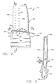
- FIG. 1 Illustrated in Figure 1 is an exemplary turbine rotor blade 10 extending radially outwardly from the perimeter of a turbine rotor disk 12, shown in part.
- the turbine blade is configured for use in the first turbine stage of a gas turbine engine in which a full row of the blades is disposed directly downstream from a cooperating high pressure turbine nozzle (not shown) which directs hot combustion gases 14 over the turbine blades which extract energy therefrom for rotating the disk and powering a compressor (not shown).
- the compressor pressurizes air 16, a portion of which is diverted to the turbine blades which are hollow for internal cooling thereof. Most of the pressurized air is mixed with fuel in a combustor (not shown) for generating the hot combustion gases 14 which flow over the turbine blades during operation.
- Each blade 10 is typically a unitary casting of high strength metal suitable for withstanding the high temperature of the combustion gases during operation.
- Each blade includes an airfoil 18, platform 20, shank 22, and dovetail 24 having any conventional integral configuration.
- the airfoil 18 includes a generally concave pressure side 18a and an opposite, generally convex suction side 18b extending radially in span from a root 18c to a tip 18d and axially between leading and trailing edges 18e,f.
- the platform 20 includes a radially outer surface 20a which defines a portion of the inner boundary for the hot combustion gases 14, and an opposite, radially inner surface 20b.
- the platform surfaces extend circumferentially from opposite side edges 20c, and axially between leading and trailing edges 20d,e.
- the shank 22 which is better illustrated in Figure 2, provides a radial transition from the platform to the supporting dovetail 24.
- the dovetail 24 as illustrated in Figure 1 may have any conventional configuration and typically includes one or more pairs of serpentine lobes which extend axially for engaging corresponding axial-entry dovetail slots 26 formed in the perimeter of the rotor disk.
- the turbine blade is hollow with a flow channel 28 extending radially or longitudinally along the span thereof, with an inlet at the bottom of the dovetail 24 and terminating at the airfoil tip 18d.
- the flow channel 28 may have any conventional configuration and typically includes multiple serpentine passes for circulating the cooling air 16 inside the airfoil for internally cooling the airfoil for removing heat therefrom when exposed to the hot combustion gases flowing outside thereof.
- the airfoil includes various holes 30 extending through the walls thereof for discharging the cooling air into the combustion gas stream.
- the airfoil holes 30 may have any conventional form such as film cooling holes which are disposed in radial rows for generating insulating films of cooling air.
- the platform 20 extends laterally outwardly both circumferentially and axially from both the airfoil and shank at a corresponding junction therewith.
- the shank 22 adjoins the inner surface of the platform at an arcuate inner fillet 32
- the airfoil adjoins the outer surface of the platform at an arcuate outer fillet 34.
- the fillets provide an aerodynamically smooth junction between the platform and the airfoil, and minimize stress concentrations under the considerable centrifugal loads generated during rotary operation of the blades.
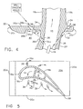
- a pair of discrete shank and platform holes 36, 38 are disposed in tandem through the shank 22 and platform 20, respectively.
- the shank hole 36 includes an inlet 36a inside the shank in flow communication with the flow channel 28, and an outlet 36b outside the shank for discharging a jet of the cooling air 16 therethrough.
- the cooperating platform hole 38 includes an inlet 38a disposed below the platform on the inner surface 20b thereof in alignment with the shank outlet hole.
- the platform hole also includes an outlet 38b disposed above the platform on the outer surface 20a thereof.
- the tandem shank and platform holes 36,38 cooperate as a pair for improving cooling of the platform 20 subject to the hot combustion gases on its outer surface 20a.
- the shank hole 36 first receives a portion of the cooling air from the internal flow channel 28 which is discharged from the shank hole outlet 36b toward the platform hole inlet 38a.
- the shank hole 36 is spaced from the inner surface of the platform by an under platform cavity 40 in which additional cooling air may be channeled in a conventional manner.
- the platform hole 38 is spaced above the shank 22 and receives its cooling air from its cooperating shank hole after bridging or traversing the respective portion of the cavity 40.
- tandem holes 36,38 extend separately through the shank and platform in series flow communication with the flow channel 28 inside the shank.
- the tandem holes are preferably inclined in series for bridging the cavity 40 and distributing the cooling air from the shank hole 36 both inside the cooperating platform hole 38, as well as outside thereof in impingement against the inner surface of the platform around the inlet of the platform hole.
- the shank hole discharges a local jet of cooling air toward the cooperating platform hole to feed the inside of that hole as well as effecting local impingement cooling therearound.
- the cooling air received from the flow channel 28 firstly is used to convectively cool the inside of the shank hole 36, and then impingement cools the underside of the platform, and then convectively cools the inside of the platform hole 38, and then is discharged from the inclined platform hole to form a film of cooling air for providing yet additional use of the same air in synergistic series cooling.
- the same air is thusly used multiple times for maximizing the cooling efficiency thereof prior to rejoining the combustion flowpath.
- the tandem holes 36,38 are preferably inclined in part outwardly through the platform toward corresponding ones of the platform side edges 20c, and inclined outwardly in part through the platform aft or downstream toward the platform trailing edge 20e in a compound inclination.
- the cooling air discharged from the platform hole 38 creates a cooling air film downstream therefrom for protecting the outer surface of the platform.
- the shank hole 36 illustrated in Figure 4 preferably terminates radially inboard of the inner fillet 32 so that the two tandem holes 36,38 are spaced radially and circumferentially apart at the inner fillet 32 while being aligned in series flow communication for bridging the platform and shank across the inner fillet with air discharged from the flow channel.
- the jet of air discharged from the shank hole 36 partially expands in the cavity 40 for impingement cooling the underside of the platform around the cooperating platform hole 38, with a central portion of the jet being injected through the platform hole 38 for flow therethrough.
- tandem holes 36,38 are preferably coaxially aligned with each other in a straight and inclined line for ensuring a straight flowpath for channeling at least some of the air ejected form the shank hole 36 into the cooperating platform hole 38.
- tandem holes 36,38 have substantially equal diameters.
- the platform hole inlet 38a is substantially equal in size with the shank hole outlet 36b for receiving the jet of cooling air therefrom, with some of that jet impinging the underside of the platform around the platform hole.
- the platform hole 38 is larger in diameter than the cooperating shank hole 36.
- the platform hole inlet in this embodiment is suitably larger in size than the shank hole outlet.
- the diameters of each of the shank and platform holes is substantially equal or constant from the respective inlet to outlet ends thereof.
- the platform 20 preferably includes a plurality of the tandem holes 36,38 arranged in a row terminating in the platform outer surface along at least one side of the airfoil, such as the pressure side 18a.
- the tandem holes are spaced apart axially between the leading and trailing edges of the platform for distributing their improved cooling effectiveness across the platform.
- tandem holes 36,38 may be disposed along the opposite, suction side of the airfoil.: preferably near the leading edge thereof for cooling this region of the platform.
- tandem holes 36,38 described above effect multiple use of the same air for enhanced cooling of the platform. And, the tandem holes are spaced inboard from the inner fillets 32 and do not introduce any stress concentrations at the juncture of the platform and airfoil.
- tandem holes may be used in cooperation with an auxiliary film cooling hole 42 shown in Figures 2 and 5 which is preferably inclined aft through the platform, and preferably aft of one of the platform holes 38 for receiving spent impingement cooling air from the underside of the platform.
- additional film cooling holes 42 without cooperating tandem shank holes therefor, may be fed with cooling air discharged from the adjacent shank holes 36.
- the air discharged from the several shank holes 36 also film cools the underside of the platform prior to being discharged through any one of the platform or auxiliary holes 38,42.
- the platform and auxiliary holes 38,42 are preferably aligned in a row along one side, such as the pressure side of the airfoil for maximizing cooling air coverage in this region.
- tandem holes described above may be used alone to significant advantage in improving cooling of the blade platform with an efficient use of the available air. And may be additionally used with the auxiliary film cooling holes for providing additional cooling.
- tandem holes 36,38 in their preferred coaxial alignment may be readily formed by conventionally drilling the holes in sequence from outside the platform inwardly through the shank.
- the same drilling process such as laser drilling or electrical discharge machining, may be used for drilling the common diameter holes through both the platform and shank.
- a two step drilling process may be used to initially drill the smaller shank hole 36 with a common diameter through both the platform and shank, followed in turn by a second drilling operation for increasing the diameter of only the cooperating platform hole 38.
- the larger platform hole 38 may be initially drilled alone without drilling the shank hole, followed in turn by drilling the smaller shank hole 36 in the shank through the pre-drilled platform hole.
- tandem holes may be formed with generally cylindrical form, any other shape of the holes may be used to advantage.
- the tandem holes may be used to advantage for cooling turbine blade platforms when required for high temperature turbine applications.
Claims (10)
- Turbinenlaufschaufel (10), aufweisend:ein einteiliges Schaufelblatt (18), einen Schaft (22) und einen Schwalbenschwanz (24) mit einem sich durch ihn hindurch erstreckenden Längsströmungskanal (28) zur Durchführung von Kühlluft (16);eine Plattform (20), die sich seitlich an einer Verbindungsstelle des Schaufelblattes und des Schaftes nach außen erstreckt; undein Schaftloch (36), das sich durch den Schaft aus dem Strömungskanal heraus und in Abstand von der Plattform angeordnet erstreckt; gekennzeichnet durch:ein Plattformloch (38), das sich in Tandemausrichtung zu dem Schaftloch durch die Plattform erstreckt.
- Laufschaufel nach Anspruch 1, wobei die Schaft- und Plattformlöcher (36, 38) in einer Reihenanordnung durch den Schaft und die Plattform hindurch geneigt sind, um die Kühlluft aus dem Schaftloch (36) auf das Plattformloch, sowohl innerhalb des Plattformloches (38) als auch außerhalb davon bei einem Aufprall gegen die Plattform zu verteilen.
- Laufschaufel nach Anspruch 1 oder 2, wobei die Plattform (20) gegenüberliegende Seitenkanten (20c) und Vorder- und Hinterkanten (20d, 20e) enthält, und die Tandem-Schaft- und Plattformlöcher (36, 38) nach außen hinten zu der Plattformhinterkante geneigt sind.
- Laufschaufel nach Anspruch 1, 2 oder 3, wobei der Schaft (22) an die Plattform (20) an einem Übergang (32) angrenzt, und das Schaftloch (36) innerhalb des Übergangs endet.
- Laufschaufel nach einem der vorstehenden Ansprüche, wobei die Tandemlöcher (36, 38) im Wesentlichen gleiche Durchmesser aufweisen.
- Laufschaufel nach Anspruch 1, wobei sich das Paar der Löcher (36, 38) getrennt durch die Plattform und den Schaft in Reihenströmungsverbindung mit einem Luftströmungskanal (28) innerhalb des Schaftes erstreckt.
- Laufschaufel nach Anspruch 6, wobei der Schaft (22) an die Plattform (20) an einem Übergang (32) angrenzt und die Tandemlöcher an dem Übergang in Abstand und in Reihe angeordnet sind, um die Plattform und den Schaft jenseits des Übergangs mit Luft aus dem Kanal zu überbrücken.
- Laufschaufel nach Anspruch 6 oder 7, wobei die Tandemlöcher ein Schaftloch (36) beinhalten, das sich durch den Schaft (22) in einem Abstand von einem damit zusammenwirkenden Plattformloch (38) erstreckt, das sich durch die Plattform (20) erstreckt.
- Laufschaufel nach Anspruch 8, wobei das Schaftloch (36) einen Einlass (36a) innerhalb des Schaftes (22) und einen Auslass (36b) außerhalb des Schaftes enthält; und
das Plattformloch (38) einen Einlass (38a) unterhalb der Plattform (20), der zu dem Schaftlochauslass (36b) ausgerichtet ist, und einen Auslass (38b) über der Plattform enthält. - Laufschaufel nach Anspruch 9, wobei die Tandemlöcher (36, 38) koaxial ausgerichtet sind.
Applications Claiming Priority (2)
| Application Number | Priority Date | Filing Date | Title |
|---|---|---|---|
| US09/628,152 US6341939B1 (en) | 2000-07-31 | 2000-07-31 | Tandem cooling turbine blade |
| US628152 | 2000-07-31 |
Publications (3)
| Publication Number | Publication Date |
|---|---|
| EP1178181A2 EP1178181A2 (de) | 2002-02-06 |
| EP1178181A3 EP1178181A3 (de) | 2003-06-04 |
| EP1178181B1 true EP1178181B1 (de) | 2006-04-19 |
Family
ID=24517694
Family Applications (1)
| Application Number | Title | Priority Date | Filing Date |
|---|---|---|---|
| EP01306433A Expired - Lifetime EP1178181B1 (de) | 2000-07-31 | 2001-07-26 | Tandemkühlung für eine Turbinenschaufel |
Country Status (4)
| Country | Link |
|---|---|
| US (1) | US6341939B1 (de) |
| EP (1) | EP1178181B1 (de) |
| JP (1) | JP4675003B2 (de) |
| DE (1) | DE60118848T2 (de) |
Cited By (1)
| Publication number | Priority date | Publication date | Assignee | Title |
|---|---|---|---|---|
| RU2550230C2 (ru) * | 2009-03-13 | 2015-05-10 | Снекма | Турбинная лопатка с обеспыливающим отверстием в основании лопасти |
Families Citing this family (54)
| Publication number | Priority date | Publication date | Assignee | Title |
|---|---|---|---|---|
| GB2365079B (en) * | 2000-07-29 | 2004-09-22 | Rolls Royce Plc | Blade platform cooling |
| JP4508432B2 (ja) * | 2001-01-09 | 2010-07-21 | 三菱重工業株式会社 | ガスタービンの冷却構造 |
| US6923616B2 (en) * | 2003-09-02 | 2005-08-02 | General Electric Company | Methods and apparatus for cooling gas turbine engine rotor assemblies |
| US7600972B2 (en) * | 2003-10-31 | 2009-10-13 | General Electric Company | Methods and apparatus for cooling gas turbine engine rotor assemblies |
| JP2005233141A (ja) | 2004-02-23 | 2005-09-02 | Mitsubishi Heavy Ind Ltd | 動翼およびその動翼を用いたガスタービン |
| DE102004029696A1 (de) * | 2004-06-15 | 2006-01-05 | Rolls-Royce Deutschland Ltd & Co Kg | Plattformkühlanordnung für den Leitschaufelkranz einer Gasturbine |
| US7131817B2 (en) * | 2004-07-30 | 2006-11-07 | General Electric Company | Method and apparatus for cooling gas turbine engine rotor blades |
| US7186089B2 (en) * | 2004-11-04 | 2007-03-06 | Siemens Power Generation, Inc. | Cooling system for a platform of a turbine blade |
| US7452184B2 (en) * | 2004-12-13 | 2008-11-18 | Pratt & Whitney Canada Corp. | Airfoil platform impingement cooling |
| US7217096B2 (en) * | 2004-12-13 | 2007-05-15 | General Electric Company | Fillet energized turbine stage |
| US7134842B2 (en) * | 2004-12-24 | 2006-11-14 | General Electric Company | Scalloped surface turbine stage |
| US7249933B2 (en) * | 2005-01-10 | 2007-07-31 | General Electric Company | Funnel fillet turbine stage |
| US7708525B2 (en) * | 2005-02-17 | 2010-05-04 | United Technologies Corporation | Industrial gas turbine blade assembly |
| US7220100B2 (en) * | 2005-04-14 | 2007-05-22 | General Electric Company | Crescentic ramp turbine stage |
| US20060269409A1 (en) * | 2005-05-27 | 2006-11-30 | Mitsubishi Heavy Industries, Ltd. | Gas turbine moving blade having a platform, a method of forming the moving blade, a sealing plate, and a gas turbine having these elements |
| US7244101B2 (en) * | 2005-10-04 | 2007-07-17 | General Electric Company | Dust resistant platform blade |
| EP1857635A1 (de) | 2006-05-18 | 2007-11-21 | Siemens Aktiengesellschaft | Turbinenschaufel für eine Gasturbine |
| US7597536B1 (en) | 2006-06-14 | 2009-10-06 | Florida Turbine Technologies, Inc. | Turbine airfoil with de-coupled platform |
| US7927073B2 (en) * | 2007-01-04 | 2011-04-19 | Siemens Energy, Inc. | Advanced cooling method for combustion turbine airfoil fillets |
| US7621718B1 (en) | 2007-03-28 | 2009-11-24 | Florida Turbine Technologies, Inc. | Turbine vane with leading edge fillet region impingement cooling |
| FR2927356B1 (fr) * | 2008-02-07 | 2013-03-01 | Snecma | Aubes pour roue a aubes de turbomachine avec rainure pour le refroidissement. |
| US20090206011A1 (en) * | 2008-02-20 | 2009-08-20 | Cudahy George F | Vibrating Screen Apparatus |
| US8057178B2 (en) * | 2008-09-04 | 2011-11-15 | General Electric Company | Turbine bucket for a turbomachine and method of reducing bow wave effects at a turbine bucket |
| US8226365B2 (en) * | 2009-04-22 | 2012-07-24 | General Electric Company | Systems, methods, and apparatus for thermally isolating a turbine rotor wheel |
| US8727726B2 (en) * | 2009-08-11 | 2014-05-20 | General Electric Company | Turbine endwall cooling arrangement |
| US8668454B2 (en) * | 2010-03-03 | 2014-03-11 | Siemens Energy, Inc. | Turbine airfoil fillet cooling system |
| US8540486B2 (en) * | 2010-03-22 | 2013-09-24 | General Electric Company | Apparatus for cooling a bucket assembly |
| EP2423435A1 (de) | 2010-08-30 | 2012-02-29 | Siemens Aktiengesellschaft | Schaufel für eine Turbomaschine |
| US8641368B1 (en) * | 2011-01-25 | 2014-02-04 | Florida Turbine Technologies, Inc. | Industrial turbine blade with platform cooling |
| JP2011241836A (ja) * | 2011-08-02 | 2011-12-01 | Mitsubishi Heavy Ind Ltd | ガスタービン動翼のプラットフォーム冷却構造 |
| US8870525B2 (en) | 2011-11-04 | 2014-10-28 | General Electric Company | Bucket assembly for turbine system |
| US8840370B2 (en) | 2011-11-04 | 2014-09-23 | General Electric Company | Bucket assembly for turbine system |
| US8845289B2 (en) | 2011-11-04 | 2014-09-30 | General Electric Company | Bucket assembly for turbine system |
| US9051842B2 (en) * | 2012-01-05 | 2015-06-09 | General Electric Company | System and method for cooling turbine blades |
| US9127561B2 (en) | 2012-03-01 | 2015-09-08 | General Electric Company | Turbine bucket with contoured internal rib |
| US9109454B2 (en) | 2012-03-01 | 2015-08-18 | General Electric Company | Turbine bucket with pressure side cooling |
| US8974182B2 (en) | 2012-03-01 | 2015-03-10 | General Electric Company | Turbine bucket with a core cavity having a contoured turn |
| US9243503B2 (en) * | 2012-05-23 | 2016-01-26 | General Electric Company | Components with microchannel cooled platforms and fillets and methods of manufacture |
| US9017033B2 (en) * | 2012-06-07 | 2015-04-28 | United Technologies Corporation | Fan blade platform |
| US9091180B2 (en) | 2012-07-19 | 2015-07-28 | Siemens Energy, Inc. | Airfoil assembly including vortex reducing at an airfoil leading edge |
| US9243501B2 (en) * | 2012-09-11 | 2016-01-26 | United Technologies Corporation | Turbine airfoil platform rail with gusset |
| US20140182292A1 (en) * | 2012-12-29 | 2014-07-03 | United Technologies Corporation | Integral instrumentation in additively manufactured components of gas turbine engines |
| EP2959130B1 (de) | 2013-02-19 | 2019-10-09 | United Technologies Corporation | Gasturbinenschaufel, gusskern für die herstellung der schaufel, und herstellungsverfahren für den gusskern |
| WO2015050730A1 (en) * | 2013-10-03 | 2015-04-09 | United Technologies Corporation | Rotating turbine vane bearing cooling |
| US20160305324A1 (en) * | 2013-12-05 | 2016-10-20 | United Technologies Corporation | Gas turbine engines with intercoolers and recuperators |
| US10689988B2 (en) * | 2014-06-12 | 2020-06-23 | Raytheon Technologies Corporation | Disk lug impingement for gas turbine engine airfoil |
| US20160146016A1 (en) * | 2014-11-24 | 2016-05-26 | General Electric Company | Rotor rim impingement cooling |
| EP3088673B1 (de) * | 2015-04-28 | 2017-11-01 | Siemens Aktiengesellschaft | Laufschaufel für eine gasturbine, zugehöriger rotor, gasturbine und kraftwerksanlage |
| CN105806873B (zh) * | 2016-03-17 | 2018-12-11 | 上海发电设备成套设计研究院 | 燃机透平叶片降温等膨胀比冷效试验装置 |
| CN105806874B (zh) * | 2016-03-17 | 2018-05-11 | 上海发电设备成套设计研究院 | 燃机透平叶片全温等膨胀比冷效试验装置 |
| US10807154B2 (en) * | 2016-12-13 | 2020-10-20 | General Electric Company | Integrated casting core-shell structure for making cast component with cooling holes in inaccessible locations |
| KR102095032B1 (ko) * | 2018-03-23 | 2020-04-23 | 두산중공업 주식회사 | 터빈 블레이드 성형 방법 |
| US11162369B1 (en) * | 2020-05-04 | 2021-11-02 | Raytheon Technologies Corporation | Turbine blade cooling hole combination |
| CN113404549A (zh) * | 2021-07-26 | 2021-09-17 | 中国船舶重工集团公司第七0三研究所 | 一种带有伸根部供气孔及缘板气膜孔的涡轮动叶 |
Family Cites Families (10)
| Publication number | Priority date | Publication date | Assignee | Title |
|---|---|---|---|---|
| US4040767A (en) * | 1975-06-02 | 1977-08-09 | United Technologies Corporation | Coolable nozzle guide vane |
| IT1079131B (it) * | 1975-06-30 | 1985-05-08 | Gen Electric | Perfezionato raffreddamento applicabile particolarmente a elementi di turbomotori a gas |
| GB1605219A (en) * | 1975-10-02 | 1984-08-30 | Rolls Royce | Stator vane for a gas turbine engine |
| GB2119027A (en) * | 1982-04-24 | 1983-11-09 | Rolls Royce | Turbine assembly for a gas turbine engine |
| JPH0211801A (ja) * | 1988-06-29 | 1990-01-16 | Hitachi Ltd | ガスタービン冷却動翼 |
| US5340278A (en) | 1992-11-24 | 1994-08-23 | United Technologies Corporation | Rotor blade with integral platform and a fillet cooling passage |
| US5382135A (en) * | 1992-11-24 | 1995-01-17 | United Technologies Corporation | Rotor blade with cooled integral platform |
| FR2758855B1 (fr) * | 1997-01-30 | 1999-02-26 | Snecma | Systeme de ventilation des plates-formes des aubes mobiles |
| CA2262064C (en) * | 1998-02-23 | 2002-09-03 | Mitsubishi Heavy Industries, Ltd. | Gas turbine moving blade platform |
| US6231307B1 (en) * | 1999-06-01 | 2001-05-15 | General Electric Company | Impingement cooled airfoil tip |
-
2000
- 2000-07-31 US US09/628,152 patent/US6341939B1/en not_active Expired - Lifetime
-
2001
- 2001-07-26 EP EP01306433A patent/EP1178181B1/de not_active Expired - Lifetime
- 2001-07-26 DE DE60118848T patent/DE60118848T2/de not_active Expired - Lifetime
- 2001-07-30 JP JP2001228812A patent/JP4675003B2/ja not_active Expired - Fee Related
Cited By (1)
| Publication number | Priority date | Publication date | Assignee | Title |
|---|---|---|---|---|
| RU2550230C2 (ru) * | 2009-03-13 | 2015-05-10 | Снекма | Турбинная лопатка с обеспыливающим отверстием в основании лопасти |
Also Published As
| Publication number | Publication date |
|---|---|
| DE60118848T2 (de) | 2007-05-16 |
| JP4675003B2 (ja) | 2011-04-20 |
| EP1178181A2 (de) | 2002-02-06 |
| JP2002129905A (ja) | 2002-05-09 |
| EP1178181A3 (de) | 2003-06-04 |
| DE60118848D1 (de) | 2006-05-24 |
| US6341939B1 (en) | 2002-01-29 |
Similar Documents
| Publication | Publication Date | Title |
|---|---|---|
| EP1178181B1 (de) | Tandemkühlung für eine Turbinenschaufel | |
| EP1001137B1 (de) | Gasturbinenschaufel mit serpentinenförmigen Kühlkanälen | |
| US6402471B1 (en) | Turbine blade for gas turbine engine and method of cooling same | |
| EP0777818B1 (de) | Gasturbinenschaufel mit gekühlter plattform | |
| US7097426B2 (en) | Cascade impingement cooled airfoil | |
| US6416284B1 (en) | Turbine blade for gas turbine engine and method of cooling same | |
| US5498133A (en) | Pressure regulated film cooling | |
| US6955522B2 (en) | Method and apparatus for cooling an airfoil | |
| EP1221538B1 (de) | Gekühlte Turbinenleitschaufel | |
| CA2551218C (en) | Counterflow film cooled wall | |
| EP1793087B1 (de) | Turbinenschaufel mit stumpfer Spitze | |
| EP1072757B1 (de) | Staubeständige Schaufelkühlung | |
| US6884036B2 (en) | Complementary cooled turbine nozzle | |
| US6290463B1 (en) | Slotted impingement cooling of airfoil leading edge | |
| EP1001136B1 (de) | Strömungsmaschinenschaufel mit aparter Kühlung der Anströmkante | |
| US6200087B1 (en) | Pressure compensated turbine nozzle | |
| EP1001135A2 (de) | Turbinenschaufel mit serieller Prallkühlung | |
| US20050232769A1 (en) | Thermal shield turbine airfoil | |
| US6382908B1 (en) | Nozzle fillet backside cooling | |
| US5511946A (en) | Cooled airfoil tip corner |
Legal Events
| Date | Code | Title | Description |
|---|---|---|---|
| PUAI | Public reference made under article 153(3) epc to a published international application that has entered the european phase |
Free format text: ORIGINAL CODE: 0009012 |
|
| AK | Designated contracting states |
Kind code of ref document: A2 Designated state(s): AT BE CH CY DE DK ES FI FR GB GR IE IT LI LU MC NL PT SE TR |
|
| AX | Request for extension of the european patent |
Free format text: AL;LT;LV;MK;RO;SI |
|
| PUAL | Search report despatched |
Free format text: ORIGINAL CODE: 0009013 |
|
| AK | Designated contracting states |
Designated state(s): AT BE CH CY DE DK ES FI FR GB GR IE IT LI LU MC NL PT SE TR |
|
| AX | Request for extension of the european patent |
Extension state: AL LT LV MK RO SI |
|
| 17P | Request for examination filed |
Effective date: 20031204 |
|
| AKX | Designation fees paid |
Designated state(s): DE FR GB IT |
|
| 17Q | First examination report despatched |
Effective date: 20050304 |
|
| GRAP | Despatch of communication of intention to grant a patent |
Free format text: ORIGINAL CODE: EPIDOSNIGR1 |
|
| GRAS | Grant fee paid |
Free format text: ORIGINAL CODE: EPIDOSNIGR3 |
|
| GRAA | (expected) grant |
Free format text: ORIGINAL CODE: 0009210 |
|
| AK | Designated contracting states |
Kind code of ref document: B1 Designated state(s): DE FR GB IT |
|
| REG | Reference to a national code |
Ref country code: GB Ref legal event code: FG4D |
|
| REF | Corresponds to: |
Ref document number: 60118848 Country of ref document: DE Date of ref document: 20060524 Kind code of ref document: P |
|
| ET | Fr: translation filed | ||
| PLBE | No opposition filed within time limit |
Free format text: ORIGINAL CODE: 0009261 |
|
| STAA | Information on the status of an ep patent application or granted ep patent |
Free format text: STATUS: NO OPPOSITION FILED WITHIN TIME LIMIT |
|
| 26N | No opposition filed |
Effective date: 20070122 |
|
| REG | Reference to a national code |
Ref country code: FR Ref legal event code: PLFP Year of fee payment: 15 |
|
| PGFP | Annual fee paid to national office [announced via postgrant information from national office to epo] |
Ref country code: DE Payment date: 20150729 Year of fee payment: 15 Ref country code: GB Payment date: 20150727 Year of fee payment: 15 |
|
| PGFP | Annual fee paid to national office [announced via postgrant information from national office to epo] |
Ref country code: FR Payment date: 20150717 Year of fee payment: 15 |
|
| PGFP | Annual fee paid to national office [announced via postgrant information from national office to epo] |
Ref country code: IT Payment date: 20150727 Year of fee payment: 15 |
|
| REG | Reference to a national code |
Ref country code: DE Ref legal event code: R119 Ref document number: 60118848 Country of ref document: DE |
|
| GBPC | Gb: european patent ceased through non-payment of renewal fee |
Effective date: 20160726 |
|
| PG25 | Lapsed in a contracting state [announced via postgrant information from national office to epo] |
Ref country code: DE Free format text: LAPSE BECAUSE OF NON-PAYMENT OF DUE FEES Effective date: 20170201 Ref country code: FR Free format text: LAPSE BECAUSE OF NON-PAYMENT OF DUE FEES Effective date: 20160801 |
|
| REG | Reference to a national code |
Ref country code: FR Ref legal event code: ST Effective date: 20170331 |
|
| PG25 | Lapsed in a contracting state [announced via postgrant information from national office to epo] |
Ref country code: GB Free format text: LAPSE BECAUSE OF NON-PAYMENT OF DUE FEES Effective date: 20160726 |
|
| PG25 | Lapsed in a contracting state [announced via postgrant information from national office to epo] |
Ref country code: IT Free format text: LAPSE BECAUSE OF NON-PAYMENT OF DUE FEES Effective date: 20160726 |