EP1177966A2 - Hollow rack shaft - Google Patents
Hollow rack shaft Download PDFInfo
- Publication number
- EP1177966A2 EP1177966A2 EP01118710A EP01118710A EP1177966A2 EP 1177966 A2 EP1177966 A2 EP 1177966A2 EP 01118710 A EP01118710 A EP 01118710A EP 01118710 A EP01118710 A EP 01118710A EP 1177966 A2 EP1177966 A2 EP 1177966A2
- Authority
- EP
- European Patent Office
- Prior art keywords
- plate
- area
- rack shaft
- sides
- row
- Prior art date
- Legal status (The legal status is an assumption and is not a legal conclusion. Google has not performed a legal analysis and makes no representation as to the accuracy of the status listed.)
- Granted
Links
Images




Classifications
-
- B—PERFORMING OPERATIONS; TRANSPORTING
- B21—MECHANICAL METAL-WORKING WITHOUT ESSENTIALLY REMOVING MATERIAL; PUNCHING METAL
- B21D—WORKING OR PROCESSING OF SHEET METAL OR METAL TUBES, RODS OR PROFILES WITHOUT ESSENTIALLY REMOVING MATERIAL; PUNCHING METAL
- B21D43/00—Feeding, positioning or storing devices combined with, or arranged in, or specially adapted for use in connection with, apparatus for working or processing sheet metal, metal tubes or metal profiles; Associations therewith of cutting devices
- B21D43/28—Associations of cutting devices therewith
- B21D43/285—Devices for handling elongated articles, e.g. bars, tubes or profiles
-
- B—PERFORMING OPERATIONS; TRANSPORTING
- B21—MECHANICAL METAL-WORKING WITHOUT ESSENTIALLY REMOVING MATERIAL; PUNCHING METAL
- B21C—MANUFACTURE OF METAL SHEETS, WIRE, RODS, TUBES, PROFILES OR LIKE SEMI-MANUFACTURED PRODUCTS OTHERWISE THAN BY ROLLING; AUXILIARY OPERATIONS USED IN CONNECTION WITH METAL-WORKING WITHOUT ESSENTIALLY REMOVING MATERIAL
- B21C37/00—Manufacture of metal sheets, rods, wire, tubes, profiles or like semi-manufactured products, not otherwise provided for; Manufacture of tubes of special shape
- B21C37/06—Manufacture of metal sheets, rods, wire, tubes, profiles or like semi-manufactured products, not otherwise provided for; Manufacture of tubes of special shape of tubes or metal hoses; Combined procedures for making tubes, e.g. for making multi-wall tubes
- B21C37/15—Making tubes of special shape; Making tube fittings
- B21C37/155—Making tubes with non-circular section
-
- B—PERFORMING OPERATIONS; TRANSPORTING
- B21—MECHANICAL METAL-WORKING WITHOUT ESSENTIALLY REMOVING MATERIAL; PUNCHING METAL
- B21D—WORKING OR PROCESSING OF SHEET METAL OR METAL TUBES, RODS OR PROFILES WITHOUT ESSENTIALLY REMOVING MATERIAL; PUNCHING METAL
- B21D35/00—Combined processes according to or processes combined with methods covered by groups B21D1/00 - B21D31/00
- B21D35/002—Processes combined with methods covered by groups B21D1/00 - B21D31/00
- B21D35/005—Processes combined with methods covered by groups B21D1/00 - B21D31/00 characterized by the material of the blank or the workpiece
- B21D35/006—Blanks having varying thickness, e.g. tailored blanks
-
- B—PERFORMING OPERATIONS; TRANSPORTING
- B21—MECHANICAL METAL-WORKING WITHOUT ESSENTIALLY REMOVING MATERIAL; PUNCHING METAL
- B21D—WORKING OR PROCESSING OF SHEET METAL OR METAL TUBES, RODS OR PROFILES WITHOUT ESSENTIALLY REMOVING MATERIAL; PUNCHING METAL
- B21D53/00—Making other particular articles
- B21D53/88—Making other particular articles other parts for vehicles, e.g. cowlings, mudguards
-
- B—PERFORMING OPERATIONS; TRANSPORTING
- B21—MECHANICAL METAL-WORKING WITHOUT ESSENTIALLY REMOVING MATERIAL; PUNCHING METAL
- B21K—MAKING FORGED OR PRESSED METAL PRODUCTS, e.g. HORSE-SHOES, RIVETS, BOLTS OR WHEELS
- B21K1/00—Making machine elements
- B21K1/06—Making machine elements axles or shafts
- B21K1/12—Making machine elements axles or shafts of specially-shaped cross-section
-
- B—PERFORMING OPERATIONS; TRANSPORTING
- B21—MECHANICAL METAL-WORKING WITHOUT ESSENTIALLY REMOVING MATERIAL; PUNCHING METAL
- B21K—MAKING FORGED OR PRESSED METAL PRODUCTS, e.g. HORSE-SHOES, RIVETS, BOLTS OR WHEELS
- B21K1/00—Making machine elements
- B21K1/76—Making machine elements elements not mentioned in one of the preceding groups
- B21K1/767—Toothed racks
-
- B—PERFORMING OPERATIONS; TRANSPORTING
- B21—MECHANICAL METAL-WORKING WITHOUT ESSENTIALLY REMOVING MATERIAL; PUNCHING METAL
- B21K—MAKING FORGED OR PRESSED METAL PRODUCTS, e.g. HORSE-SHOES, RIVETS, BOLTS OR WHEELS
- B21K1/00—Making machine elements
- B21K1/76—Making machine elements elements not mentioned in one of the preceding groups
- B21K1/767—Toothed racks
- B21K1/768—Toothed racks hollow
-
- B—PERFORMING OPERATIONS; TRANSPORTING
- B62—LAND VEHICLES FOR TRAVELLING OTHERWISE THAN ON RAILS
- B62D—MOTOR VEHICLES; TRAILERS
- B62D3/00—Steering gears
- B62D3/02—Steering gears mechanical
- B62D3/12—Steering gears mechanical of rack-and-pinion type
- B62D3/126—Steering gears mechanical of rack-and-pinion type characterised by the rack
-
- Y—GENERAL TAGGING OF NEW TECHNOLOGICAL DEVELOPMENTS; GENERAL TAGGING OF CROSS-SECTIONAL TECHNOLOGIES SPANNING OVER SEVERAL SECTIONS OF THE IPC; TECHNICAL SUBJECTS COVERED BY FORMER USPC CROSS-REFERENCE ART COLLECTIONS [XRACs] AND DIGESTS
- Y10—TECHNICAL SUBJECTS COVERED BY FORMER USPC
- Y10T—TECHNICAL SUBJECTS COVERED BY FORMER US CLASSIFICATION
- Y10T29/00—Metal working
- Y10T29/49—Method of mechanical manufacture
- Y10T29/49462—Gear making
-
- Y—GENERAL TAGGING OF NEW TECHNOLOGICAL DEVELOPMENTS; GENERAL TAGGING OF CROSS-SECTIONAL TECHNOLOGIES SPANNING OVER SEVERAL SECTIONS OF THE IPC; TECHNICAL SUBJECTS COVERED BY FORMER USPC CROSS-REFERENCE ART COLLECTIONS [XRACs] AND DIGESTS
- Y10—TECHNICAL SUBJECTS COVERED BY FORMER USPC
- Y10T—TECHNICAL SUBJECTS COVERED BY FORMER US CLASSIFICATION
- Y10T29/00—Metal working
- Y10T29/49—Method of mechanical manufacture
- Y10T29/49462—Gear making
- Y10T29/49467—Gear shaping
-
- Y—GENERAL TAGGING OF NEW TECHNOLOGICAL DEVELOPMENTS; GENERAL TAGGING OF CROSS-SECTIONAL TECHNOLOGIES SPANNING OVER SEVERAL SECTIONS OF THE IPC; TECHNICAL SUBJECTS COVERED BY FORMER USPC CROSS-REFERENCE ART COLLECTIONS [XRACs] AND DIGESTS
- Y10—TECHNICAL SUBJECTS COVERED BY FORMER USPC
- Y10T—TECHNICAL SUBJECTS COVERED BY FORMER US CLASSIFICATION
- Y10T29/00—Metal working
- Y10T29/49—Method of mechanical manufacture
- Y10T29/49462—Gear making
- Y10T29/49467—Gear shaping
- Y10T29/49474—Die-press shaping
-
- Y—GENERAL TAGGING OF NEW TECHNOLOGICAL DEVELOPMENTS; GENERAL TAGGING OF CROSS-SECTIONAL TECHNOLOGIES SPANNING OVER SEVERAL SECTIONS OF THE IPC; TECHNICAL SUBJECTS COVERED BY FORMER USPC CROSS-REFERENCE ART COLLECTIONS [XRACs] AND DIGESTS
- Y10—TECHNICAL SUBJECTS COVERED BY FORMER USPC
- Y10T—TECHNICAL SUBJECTS COVERED BY FORMER US CLASSIFICATION
- Y10T29/00—Metal working
- Y10T29/49—Method of mechanical manufacture
- Y10T29/49826—Assembling or joining
- Y10T29/49906—Metal deforming with nonmetallic bonding
-
- Y—GENERAL TAGGING OF NEW TECHNOLOGICAL DEVELOPMENTS; GENERAL TAGGING OF CROSS-SECTIONAL TECHNOLOGIES SPANNING OVER SEVERAL SECTIONS OF THE IPC; TECHNICAL SUBJECTS COVERED BY FORMER USPC CROSS-REFERENCE ART COLLECTIONS [XRACs] AND DIGESTS
- Y10—TECHNICAL SUBJECTS COVERED BY FORMER USPC
- Y10T—TECHNICAL SUBJECTS COVERED BY FORMER US CLASSIFICATION
- Y10T74/00—Machine element or mechanism
- Y10T74/19—Gearing
- Y10T74/19642—Directly cooperating gears
- Y10T74/1967—Rack and pinion
Definitions
- the present invention relates to a hollow rack shaft, particularly relates to a hollow rack shaft used for a steering system of an automobile.
- a hollow rack shaft used for a steering system of an automobile and its manufacturing method are disclosed in Japanese Laid-Open Patents No. Hei 11-180318 and No. Hei 11-278287 and others.
- rack teeth are formed at the bottom of a U-shaped plate bent in a gutter-like shape, and afterward, the plate is formed cylindrically by butting two open legs of the U shape.
- the butt portion of the cylinder is normally welded to acquire higher strength except a case that there is no problem on the strength and this cylinder is used as a hollow rack shaft.
- Figs. 1a and 1b are a top view and a sectional view showing a workpiece for manufacturing the above shaft.
- Figs. 2a to 6c show the forming process from the material to the hollow rack shaft in this manufacturing method.
- These drawings accompanied by a, b and c are respectively equivalent to a front view of the rack shaft ( the workpiece) , a D-D sectional view of the part in which rack teeth are formed, and an E-E sectional view of the part in which no rack tooth is formed.
- the workpiece of a substantially rectangular plate shown in Figs. 1a and 1b is bent into a gutter-like shape having a U-shaped part with a flat bottom in an area A1, and having a U-shaped part with a semicircular bottom in an area A2 on both sides of A1 as shown in Figs. 2a to 2c.
- a row of rack teeth is formed at the flat bottom of the gutter-shaped workpiece as shown in Figs. 3a to 3c
- the ends of two open legs of the gutter-shaped workpiece are bent inside so that they are joined as shown in Figs. 4a to 4c.
- the section of the part in the area A2 becomes circular by this bending.
- the workpiece becomes a hollow rack shaft shown in Figs. 6a to 6c after finishing process.
- welding has the cooling contraction problem which caused by the solidification and the contraction of melted and expanded material at cooling. Internal stress is caused by the contraction through cooling of welded part, and distortion is also caused in the whole workpiece.
- Fig. 7 exaggeratingly shows the hollow rack shaft deformed in whole by the contraction through cooling of the welded part 5.
- the butt-welded part 5 is located on the reverse side to the rack teeth, the warp that the contracted welded part (a weld bead) 5 is on the inside and the row of rack teeth is on the outside is caused.
- the rack teeth are out of the standard of teeth profile and cannot be substantially used for a rack shaft as they are. That is, as the rack shaft also warps in the area A1 having the rack teeth and the precision of the teeth profile is deteriorated by this effect, the rack shaft cannot be normally engaged with a pinion.
- the hollow rack shaft has further another problem.
- a pinion coupled to a steering shaft is engaged with the rack teeth and steering force is transmitted from the pinion, large bending stress acts upon the dedendum of the rack teeth and high contact pressure acts upon the contact part of the surface of the rack teeth.
- the rack teeth are generally hardened up to approximately the hardness Hrc 60 by carburizing quenching or induction hardening. In the meantime, such high contact pressure and large bending stress do not act upon the part in which no rack teeth are formed.
- the rack shaft which is made in this method has the same diameter of the area A1 that the row of rack teeth is formed as that of the areas A2 on both sides of the area A1.
- the manufactured hollow rack shaft does not achieve enough lightening and it is high-priced.
- the invention provides a hollow rack shaft and its manufacturing method wherein a process for a butt weld is not required, therefore, the process of weld beads and the rectification of the welding warp are not required and in addition, the strength is the same as what is welded.
- the invention has the object of acquiring a low-priced and light hollow rack shaft, particularly a hollow rack shaft for a steering system and manufacturing it easily. Furthermore, the invention has an object of using an enough thick and high quality plate in order to apply enough strength to rack teeth, using a thin plate made of low-priced material for part having no rack teeth, acquiring a light and low-cost hollow rack shaft and hereby further, acquiring the useful hollow rack shaft having suitable quality and the balance of the strength as a whole.
- a workpiece for the hollow rack shaft disclosed in this specification is a substantially rectangular plate.
- the opposite two sides of this workpiece have complementary profiles each of which is composed of the continuation of a convex portion and a concave portion.
- the profiles are mutually engaged.
- the size of the widest part of the convex portion is wider than that of the narrowest part of the concave portion, the above-mentioned two sides are prevented from being detached after engagement.
- the opposite convex portion and concave portion are mutually caulked, and hereby, respective gap is filled up.
- a workpiece for another hollow rack shaft disclosed in this specification is one plate acquired by welding a first plate for a rack teeth area for a row of rack teeth to be formed and a second plate for the other area.
- a plate thicker than the second plate and/or a plate made of more satisfactory material in hardenability are/is used.
- FIG. 1 Another hollow rack shaft disclosed in this specification is provided with a first area and a second area on both sides of it.
- first area a row of rack teeth and a semi-cylindrical part on the reverse side are formed
- second area is fully cylindrical and on at least one side of the second area, a part different from the semi-cylindrical part in the first area and having a particularly small diameter is formed.
- Figs. 8a to 8c are respectively a top view and a side view showing a workpiece used in this embodiment, and an enlarged view of a part c in Fig. 8a.
- a workpiece 1 is, as a whole, a substantially rectangular plate acquired by blanking or laser cutting from coiled metal.
- the opposite two sides have complementary profiles composed of the continuation of a convex portion and a concave portion. As the phase of a convex portion and a concave portion is offset by a half of pitch p, the two sides can be mutually engaged in the relation of a male and a female.
- the two engaged sides of the workpiece 1 are not detached because the maximum width w1 of a convex portion and a concave portion is larger than the width w2 of the neck of the convex portion and the concave portion.
- This workpiece 1 has an area A1 in which a row of rack teeth is to be formed, an area A2 in which no row of rack teeth is formed and four transition areas X between these two areas (respectively when viewed along the length of the plate) as shown in Fig. 8a.
- the width of the workpiece 1 is made narrow by d1 on one side by degrees.
- the volume of the workpiece in each area is balanced by adjusting the width of the workpiece 1 in the area A1 and the area A2.
- Figs. 9a to 9c show the contour of the plate 1 after the first process and are respectively a front sectional view, a sectional view on line B-B in Fig. 9a and a sectional view on line C-C in Fig. 9a.
- the workpiece 1 is bent into a gutter-like shape by press.
- the area A1 in which the row of rack teeth would be formed has a U-shaped section having a flat bottom 1c and a pair of legs 1e respectively shown in Fig. 9c
- the area A2 in which no row of rack teeth is formed has a U-shaped section having a pair of legs 1e and a round bottom 1b respectively shown in Fig. 9b.
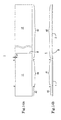
- Figs. 10a and 10b show the shape of the workpiece 1 after the second process and are respectively a front sectional view showing the workpiece 1 after rack teeth are formed and a sectional view on line B-B in Fig. 10a.
- the row of rack teeth 1d is formed by approaching the upper die having teeth equivalent to the row of rack teeth to the lower die having a corrugated shape corresponding to the rack teeth of the upper die under the state that the workpiece 1 is placed between these dies. Then, the shape of the two dies is transferred on the flat bottom of the workpiece 1.
- the workpiece 1 is formed cylindrically by bending the two legs 1e inside.
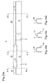
- Figs. 11a to 11d show the shape of the workpiece 1 after the third process and are respectively a front sectional view, a bottom view, a sectional view on line C-C in Fig. 11a and a sectional view on line D-D.
- Two legs 1e shown in Figs. 10a and 10b are bent inside so that a concave portion and a convex portion are mutually engaged. As the legs 1e are mutually combined by the engagement of the concave portion and the convex portion, the butt welding as conventional is not required and even if a load is applied to the rack shaft, the legs 1e are not detached.
- the two legs 1e engage more stiffly by caulking the vicinity of a connection A as the concave portion touches the convex portion which is engaged with it without clearance, and consequently, there is no gap.
- Figs. 12a to 12c are respectively an enlarged view of the vicinity of the connection A which was caulked, a sectional view on line B-B in Fig. 12a and a sectional view on line C-C in Fig. 12a.
- a substantially conical indent p is made in the vicinity of a boundary between opposite convex portions.
- a part q of the material of one convex portion is deformed by impressing as the part covers the other convex portion. This deformation prevents the gap between the convex portion and the concave portion, and that the convex portion falls off in a direction shown by arrow.
- Figs. 13a and 13b show another example of caulking and are respectively an enlarged top view of a convex portion and a sectional view on line B-B.
- the gap and the falling off of the convex portions are prevented by making an impression p in the shape of a distorted triangular pyramid across a boundary and causing deformation q on the boundary.
- Caulking described in the above-mentioned examples is arbitrary and the above-mentioned convex portion (therefore, the concave portion) is not limited to the one shown in the drawings and if only a convex portion and a concave portion can be engaged, they may have an arbitrary shape.
- Figs. 14a and 14b are respectively a top view and a front view showing a workpiece used in a second embodiment.
- the plate workpiece 1 used in the second embodiment is one substantially rectangular plate as a whole acquired by welding the two plate workpieces 11 and 12 which are different in the material and/or the thickness at a weld R.
- the material that enables carburizing quenching such as Scr and SCM or carbon steel suitable for induction hardening can be used and the workpiece 11 is made thicker than the workpiece 12 so that a row of rack teeth to be formed has enough strength.
- the workpiece 1 has an area A1 in which the row of rack teeth is formed, an area A2 in which no row of rack teeth is formed and a transition area X in which transition by d1 from the area A1 to the area A2 as in the first embodiment.
- Figs. 15a to 15d are respectively a front sectional view showing the workpiece 1 after the first process, a sectional view on line B-B, a sectional view on line C-C and a sectional view on line D-D.
- the workpiece 1 is bent into a gutter-like shape having a U-shaped section as a whole.
- any section has a pair of legs 1e, the area A1 has the section of a flat bottom 1c and the area A2 has the section of a round bottom 1b.
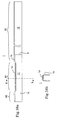
- Figs. 16a and 16b are respectively a front sectional view showing the workpiece 1 after the second process and a sectional view on line B-B.
- a row of rack teeth 1d is formed at the flat bottom 1c of the workpiece 1.
- Figs. 17a to 17d are respectively a front sectional view showing the workpiece 1 after the third process, a sectional view on line B-B, a sectional view on line C-C and a sectional view on line D-D.
- the ends of two legs 1e are bent inside as they are joined.
- the workpiece 1 is butted cylindrically. In the case that strength is required for the rack shaft, the ends are welded in butt parts P and Q.
- the workpiece 1 substantially having the shape of the rack shaft is finished by machining, the carburizing quenching of the row of rack teeth and the other location and finishing through grinding and is shipped as a hollow rack shaft.
- Figs. 18a and 18b show a different example of the workpiece 1 in the second embodiment and are respectively a top view and a side view respectively showing the workpiece 1.
- the workpiece 1 is acquired by fitting material 21 for forming a row of rack teeth in a hole of material 22 and welding them.
- the material 21 the material that enables carburizing quenching such as Scr and SCM or carbon steel suitable for induction hardening can be used and the material 21 is thickened, compared with the material 22 so that the row of rack teeth to be formed later has enough strength.
- the workpiece 1 is different, and the first to third processes are substantially similar to those in the above-mentioned examples.
- the light and low-priced hollow rack shaft can be manufactured.
- Figs. 19a and 19b are respectively a top view and a side view respectively showing a workpiece 1 used in a third embodiment.
- the workpiece 1 is one substantially rectangular plate as a whole and is similar to the workpiece in the first and second embodiments about the point that the workpiece 1 in the third embodiment also has an area A1 in which a row of rack teeth is formed, areas A2 in which no row of rack teeth is formed and a transition area X.
- the area A2 further has a wide partial area B1, a partial area B2 narrower than the area B1 by d2 on one side and a transition area Y.
- the diameter in this part of the rack shaft can be much smaller than the present. Accordingly, in the third embodiment, the diameter of a part of the completed rack shaft is reduced by narrowing the width of a part of the workpiece 1, that is, the width of the partial area B2 and the weight is reduced.
- Figs. 20a to 20d are respectively a front sectional view showing the workpiece 1 after the first process, a sectional view on line B-B, a sectional view on line C-C and a sectional view on line D-D.
- the workpiece 1 is bent into a gutter-like shape having a U-shaped section as a whole.
- each section has a pair of legs 1e, a flat bottom 1c in the area A1 and a round bottom 1b in the area A2.
- the U-shaped sections which have different size are formed in the partial areas B1 and B2 in the area A2.
- the size of U-shaped sections varies by degrees.
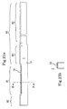
- Figs. 21a and 21b are respectively a front sectional view showing the workpiece 1 after a second process in the third embodiment and a sectional view on line B-B.
- a row of rack teeth 1d is formed at a flat bottom 1c of the workpiece 1.
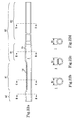
- Figs. 22a to 22d are respectively a front sectional view showing the workpiece 1 formed in the shape of a hollow cylinder, a sectional view on line B-B, a sectional view on line C-C and a sectional view on line D-D.
- the outside diameter in the sectional views on lines B-B and C-C is Dr and the outside diameter in the sectional view on line D-D is Dt that is shorter than Dr.
- Dr the outside diameter in the sectional view on line D-D
- the joined parts of the workpiece 1 substantially having the shape of the rack shaft are welded if necessary, the workpiece is finished by machining, the carburizing quenching of the row of rack teeth and the other location and grinding and is shipped as a hollow rack shaft.
- the whole is lightened without the effect on the strength of the rack shaft by reducing the outside diameter in the partial area B2 as described above.
Landscapes
- Engineering & Computer Science (AREA)
- Mechanical Engineering (AREA)
- Chemical & Material Sciences (AREA)
- Combustion & Propulsion (AREA)
- Transportation (AREA)
- Gears, Cams (AREA)
- Cabinets, Racks, Or The Like Of Rigid Construction (AREA)
Abstract
Description
Claims (14)
- A hollow rack shaft which is formed cylindrically by bending a substantially rectangular plate so that the parallel two sides are joined and in a part of the surface of which a row of rack teeth along a direction of the axis is formed, wherein:said respective sides have complementary profiles composed of the continuation of a convex portion and a concave portion so that the sides are engaged when they are joined.
- A hollow rack shaft according to Claim 1, wherein:the width of a part having the largest width of said convex portion is larger than the width of a part having the smallest width of said concave portion; andhereby, said two sides are prevented from being detached.
- A hollow rack shaft according to Claim 1, wherein:said convex portion and said concave portion mutually opposite are caulked; andhereby, mutual gap is removed.
- A method of manufacturing a hollow rack shaft which is formed cylindrically by bending the opposite sides of a substantially rectangular plate so that the sides are joined and in a part of the surface of which a row of rack teeth along a direction of the axis is formed, wherein:a complementary profile composed of the continuation of a convex portion and a concave portion is provided to said respective sides; andthe respective sides are joined owing to this profile when they are confronted so that they are not detached.
- A method of manufacturing a hollow rack shaft according to Claim 4, wherein:further, said convex portion and/or said concave portion of said joined sides are/is caulked to deform the boundary.
- A hollow rack shaft which is formed cylindrically by bending a substantially rectangular plate so that the parallel two sides are joined and in a part of the surface of which a row of rack teeth along a direction of the axis is formed, wherein:said plate is one plate acquired by welding a first plate for a rack teeth area for said row of rack teeth is to be formed and a second plate for an area except it.
- A hollow rack shaft according to Claim 6, wherein:said first plate is thicker than said second plate.
- A hollow rack shaft according to Claim 6, wherein:said first plate is made of material more satisfactory in hardenability than that of said second plate.
- A method of manufacturing a hollow rack shaft provided a row of rack teeth along a direction of the axis in a part of the surface for forming a substantially rectangular plate cylindrically by bending it so that the parallel two sides are joined, wherein:said plate is one plate acquired by welding a first plate for a rack teeth area for said row of rack teeth to be formed and a second plate for an area except it.
- A method of manufacturing a hollow rack shaft according to Claim 9, wherein:said first plate is thicker than said second plate.
- A method of manufacturing a hollow rack shaft according to Claim 9, wherein:said first plate is made of material more satisfactory in hardenability than that of said second plate.
- A hollow rack shaft which is formed cylindrically by bending a plate so that the two sides of the plate are joined and in a part of the surface of which a row of rack teeth along a direction of the axis is formed, wherein:said rack shaft is provided with a first area and second areas on both sides of it;in said first area, the row of rack teeth and a semi-cylindrical part on the reverse side are formed; andin said two second areas, a complete cylindrical part is formed and at least one of the second areas has a diameter different from the diameter of the semi-cylindrical part in said first area.
- A hollow rack shaft according to Claim 12, wherein:the diameter of at least one of said second areas is smaller than the diameter of said first area.
- A method of manufacturing a hollow rack shaft which is provide with a first area and a second area on both sides of it, in which in said first area, a row of rack teeth and a semi-cylindrical part on the reverse side are formed and in which in said two second areas, a complete cylindrical part is formed and at least one of the second areas has a diameter different from the diameter of the semi-cylindrical part in said first area, wherein:a plate provided with a part with first width having width corresponding to the first area for said row of rack teeth to be formed and a part with second width corresponding to said second area and having narrower width than said part with the first width is plastically deformed cylindrically.
Applications Claiming Priority (6)
| Application Number | Priority Date | Filing Date | Title |
|---|---|---|---|
| JP2000236982 | 2000-08-04 | ||
| JP2000236982A JP2002048220A (en) | 2000-08-04 | 2000-08-04 | Hollow rack shaft and its manufacturing method |
| JP2000269915A JP2002079350A (en) | 2000-09-06 | 2000-09-06 | Hollow rack shaft, and manufacturing method thereof |
| JP2000269915 | 2000-09-06 | ||
| JP2000269725 | 2000-09-06 | ||
| JP2000269725A JP2002079332A (en) | 2000-09-06 | 2000-09-06 | Hollow pack shaft and its manufacturing method |
Publications (3)
| Publication Number | Publication Date |
|---|---|
| EP1177966A2 true EP1177966A2 (en) | 2002-02-06 |
| EP1177966A3 EP1177966A3 (en) | 2006-04-12 |
| EP1177966B1 EP1177966B1 (en) | 2009-01-28 |
Family
ID=27344262
Family Applications (1)
| Application Number | Title | Priority Date | Filing Date |
|---|---|---|---|
| EP01118710A Expired - Lifetime EP1177966B1 (en) | 2000-08-04 | 2001-08-03 | Hollow rack shaft |
Country Status (3)
| Country | Link |
|---|---|
| US (2) | US20020020237A1 (en) |
| EP (1) | EP1177966B1 (en) |
| DE (1) | DE60137560D1 (en) |
Cited By (4)
| Publication number | Priority date | Publication date | Assignee | Title |
|---|---|---|---|---|
| EP1316492A1 (en) * | 2001-11-29 | 2003-06-04 | Neturen Co., Ltd. | A hollow steering rack bar and its manufacturing method |
| CN105050882A (en) * | 2013-06-12 | 2015-11-11 | 日本精工株式会社 | Rack-and-pinion steering gear unit |
| WO2016152146A1 (en) * | 2015-03-23 | 2016-09-29 | Neturen Co., Ltd. | Rack bar and method for manufacturing said rack bar |
| JP2020192681A (en) * | 2020-08-14 | 2020-12-03 | 高周波熱錬株式会社 | Method for manufacturing rack bar |
Families Citing this family (9)
| Publication number | Priority date | Publication date | Assignee | Title |
|---|---|---|---|---|
| DE60139361D1 (en) * | 2000-03-09 | 2009-09-10 | Nsk Ltd | Production method of a hollow rack |
| US7207231B2 (en) * | 2001-08-08 | 2007-04-24 | Trw Automotive U.S. Llc | Rack gear and method of making same |
| BRPI0414291A (en) * | 2003-09-23 | 2006-11-07 | Bishop Innovation Ltd | steering rack for a rack and pinion type steering mechanism and method of manufacture |
| US8104368B2 (en) * | 2006-02-02 | 2012-01-31 | Charles Wayne Aaron | Load bearing sprocket system |
| JP5267187B2 (en) | 2009-02-13 | 2013-08-21 | セイコーエプソン株式会社 | Cylindrical shaft, transport roller, transport unit, and printing apparatus |
| JP5453831B2 (en) | 2009-02-13 | 2014-03-26 | セイコーエプソン株式会社 | Printing device |
| CN104806728A (en) * | 2014-01-24 | 2015-07-29 | 烟台中集来福士海洋工程有限公司 | Staggered tooth rack |
| JP6444139B2 (en) * | 2014-11-06 | 2018-12-26 | 株式会社ジェイテクト | Steering device |
| CN108290600B (en) * | 2015-11-04 | 2020-09-01 | 高周波热錬株式会社 | Method of manufacturing a rack |
Family Cites Families (24)
| Publication number | Priority date | Publication date | Assignee | Title |
|---|---|---|---|---|
| US1298100A (en) | 1917-10-12 | 1919-03-25 | Rowland H Royce | Bushing. |
| US1983584A (en) | 1930-03-29 | 1934-12-11 | Urschel Engineering Company | Process of shaping metal tubes |
| US2762118A (en) | 1953-07-13 | 1956-09-11 | Gen Motors Corp | Method of forming an interlocking bushing |
| US2762117A (en) | 1953-07-13 | 1956-09-11 | Gen Motors Corp | Method of forming an interlocking bushing |
| NL258758A (en) * | 1959-12-31 | |||
| US3163925A (en) * | 1961-12-01 | 1965-01-05 | Universal Tool & Stamping Comp | Method of forming a rigid steel rack bar for automobile jacks |
| US3834247A (en) | 1972-05-31 | 1974-09-10 | M Belsdorf | Toothed rack for a rack-and-pinion steering gear of motor vehicles |
| US4133221A (en) | 1977-06-23 | 1979-01-09 | Trw, Inc. | Rack gear and method of making the same |
| US4538647A (en) | 1981-04-23 | 1985-09-03 | Saurenman Phillip E | Interlocked metal seam structure with in-plane stabilization |
| JPS58218339A (en) | 1982-06-11 | 1983-12-19 | Daido Steel Co Ltd | Steering rod for vehicle and its manufacture |
| FR2529983A1 (en) * | 1982-07-09 | 1984-01-13 | Vallourec | STEERING RACK FOR MOTOR VEHICLES |
| US4573846A (en) | 1984-09-17 | 1986-03-04 | Willbanks Weldon C | Hay bale processor |
| JPS63303218A (en) | 1987-06-02 | 1988-12-09 | Daido Metal Kogyo Kk | Joint type roll bush bearing having same-shaped joint part at both ends of joint |
| US4978104A (en) | 1989-05-10 | 1990-12-18 | Gipson Jr James H | Quick release jack |
| JP2928427B2 (en) | 1992-05-26 | 1999-08-03 | 株式会社チューブフォーミング | Apparatus and method for molding tubular rack bar |
| JPH05345231A (en) | 1992-06-15 | 1993-12-27 | Sumitomo Metal Ind Ltd | Manufacture of rack tube |
| JP3739450B2 (en) * | 1995-11-07 | 2006-01-25 | ティーアールダブリュ オートモーティブ ジャパン株式会社 | Steering rack bar with screw shaft |
| JP3633253B2 (en) * | 1997-12-19 | 2005-03-30 | 日本精工株式会社 | Hollow rack shaft and manufacturing method thereof |
| JPH11278287A (en) | 1998-03-31 | 1999-10-12 | Fuji Kiko Co Ltd | Steering rack shaft and method of manufacturing the same |
| JP2000094081A (en) * | 1998-09-14 | 2000-04-04 | Trw Automotive Japan Kk | Production of hollow rack shaft |
| JP4224157B2 (en) | 1999-01-11 | 2009-02-12 | 高周波熱錬株式会社 | Manufacturing method of hollow rack shaft |
| JP2001105067A (en) * | 1999-09-30 | 2001-04-17 | Toyota Motor Corp | Rack bar and method of manufacturing the same |
| US6442992B2 (en) | 2000-02-10 | 2002-09-03 | Nsk Ltd. | Hollow rack shaft and method of manufacturing the same |
| WO2001068434A2 (en) * | 2000-03-10 | 2001-09-20 | Delphi Technologies, Inc. | Vehicle rack and pinion steering |
-
2001
- 2001-07-30 US US09/918,117 patent/US20020020237A1/en not_active Abandoned
- 2001-08-03 EP EP01118710A patent/EP1177966B1/en not_active Expired - Lifetime
- 2001-08-03 DE DE60137560T patent/DE60137560D1/en not_active Expired - Lifetime
-
2003
- 2003-06-13 US US10/461,056 patent/US6782598B2/en not_active Expired - Lifetime
Cited By (8)
| Publication number | Priority date | Publication date | Assignee | Title |
|---|---|---|---|---|
| EP1316492A1 (en) * | 2001-11-29 | 2003-06-04 | Neturen Co., Ltd. | A hollow steering rack bar and its manufacturing method |
| CN105050882A (en) * | 2013-06-12 | 2015-11-11 | 日本精工株式会社 | Rack-and-pinion steering gear unit |
| EP3009329A4 (en) * | 2013-06-12 | 2016-06-22 | Nsk Ltd | Rack-and-pinion steering gear unit |
| US9731750B2 (en) | 2013-06-12 | 2017-08-15 | Nsk Ltd. | Rack-and-pinion steering gear unit |
| WO2016152146A1 (en) * | 2015-03-23 | 2016-09-29 | Neturen Co., Ltd. | Rack bar and method for manufacturing said rack bar |
| JP2016179475A (en) * | 2015-03-23 | 2016-10-13 | 高周波熱錬株式会社 | Rack bar, and production method of rack bar |
| CN107406093A (en) * | 2015-03-23 | 2017-11-28 | 高周波热錬株式会社 | The manufacture method of rack and the rack |
| JP2020192681A (en) * | 2020-08-14 | 2020-12-03 | 高周波熱錬株式会社 | Method for manufacturing rack bar |
Also Published As
| Publication number | Publication date |
|---|---|
| US6782598B2 (en) | 2004-08-31 |
| US20030209100A1 (en) | 2003-11-13 |
| US20020020237A1 (en) | 2002-02-21 |
| EP1177966B1 (en) | 2009-01-28 |
| EP1177966A3 (en) | 2006-04-12 |
| DE60137560D1 (en) | 2009-03-19 |
Similar Documents
| Publication | Publication Date | Title |
|---|---|---|
| EP1177966B1 (en) | Hollow rack shaft | |
| US7748743B2 (en) | Structural or chassis component for a motor vehicle, and method of making such a structural or chassis component | |
| EP1215102B1 (en) | Hollow rack shaft and manufacturing method thereof | |
| JP3452622B2 (en) | Swaging ring and manufacturing method thereof | |
| US20070234771A1 (en) | Method of Hydraulic bulging and shaft pressing profile element pipe to make hydraulically bulged product | |
| DE10024553A1 (en) | Producing assembled low weight camshaft for motor vehicle engine, using a cylindrical shaft element with a diameter dimensioned that it forms a narrow slide seat in the hub of the cam and the bearing elements | |
| US7020962B2 (en) | Method for producing a cam for a camshaft | |
| CA2262784A1 (en) | Linear friction welding process for making wheel rims | |
| US20080178650A1 (en) | Profile element pipe for hydraulic bulging, hydraulic bulging device using the element pipe, hydraulic bulging method using the element pipe, and hydraulically bulged product | |
| US8202628B2 (en) | Fusion-bonded product having high-strength part and manufacturing method thereof | |
| JP4692817B2 (en) | Drive shaft manufacturing method | |
| JPH0524322B2 (en) | ||
| US20030079516A1 (en) | Method for manufacturing a hollow rack shaft | |
| KR19980024655A (en) | Brake shoe assembly and forming method thereof | |
| US6588293B2 (en) | Hollow rack shaft | |
| US7484296B2 (en) | Camshaft and method for producing a camshaft of this type | |
| DE10322752B4 (en) | Method for producing workpieces made of sheet metal | |
| JP2652823B2 (en) | Manufacturing method of gear shaft | |
| DE102004005568A1 (en) | Connection area on a component, and method and tool for its production | |
| JP4188053B2 (en) | Shift sleeve base body | |
| JP2003094141A (en) | Manufacturing method of hollow spline shaft | |
| CN114144247A (en) | Method for manufacturing joined member | |
| JP4192511B2 (en) | Rack shaft and manufacturing method thereof | |
| JP7718617B1 (en) | Joining member, press molding die, joining method, and manufacturing method of joining member | |
| JP2004044720A (en) | Rack shaft and method of manufacturing the same |
Legal Events
| Date | Code | Title | Description |
|---|---|---|---|
| PUAI | Public reference made under article 153(3) epc to a published international application that has entered the european phase |
Free format text: ORIGINAL CODE: 0009012 |
|
| AK | Designated contracting states |
Kind code of ref document: A2 Designated state(s): AT BE CH CY DE DK ES FI FR GB GR IE IT LI LU MC NL PT SE TR |
|
| AX | Request for extension of the european patent |
Free format text: AL;LT;LV;MK;RO;SI |
|
| RAP1 | Party data changed (applicant data changed or rights of an application transferred) |
Owner name: NSK LTD., |
|
| PUAL | Search report despatched |
Free format text: ORIGINAL CODE: 0009013 |
|
| AK | Designated contracting states |
Kind code of ref document: A3 Designated state(s): AT BE CH CY DE DK ES FI FR GB GR IE IT LI LU MC NL PT SE TR |
|
| AX | Request for extension of the european patent |
Extension state: AL LT LV MK RO SI |
|
| 17P | Request for examination filed |
Effective date: 20060227 |
|
| AKX | Designation fees paid |
Designated state(s): DE FR GB |
|
| 17Q | First examination report despatched |
Effective date: 20070226 |
|
| GRAP | Despatch of communication of intention to grant a patent |
Free format text: ORIGINAL CODE: EPIDOSNIGR1 |
|
| GRAS | Grant fee paid |
Free format text: ORIGINAL CODE: EPIDOSNIGR3 |
|
| GRAA | (expected) grant |
Free format text: ORIGINAL CODE: 0009210 |
|
| AK | Designated contracting states |
Kind code of ref document: B1 Designated state(s): DE FR GB |
|
| REG | Reference to a national code |
Ref country code: GB Ref legal event code: FG4D |
|
| REF | Corresponds to: |
Ref document number: 60137560 Country of ref document: DE Date of ref document: 20090319 Kind code of ref document: P |
|
| PLBE | No opposition filed within time limit |
Free format text: ORIGINAL CODE: 0009261 |
|
| STAA | Information on the status of an ep patent application or granted ep patent |
Free format text: STATUS: NO OPPOSITION FILED WITHIN TIME LIMIT |
|
| 26N | No opposition filed |
Effective date: 20091029 |
|
| GBPC | Gb: european patent ceased through non-payment of renewal fee |
Effective date: 20090803 |
|
| REG | Reference to a national code |
Ref country code: FR Ref legal event code: ST Effective date: 20100430 |
|
| PG25 | Lapsed in a contracting state [announced via postgrant information from national office to epo] |
Ref country code: FR Free format text: LAPSE BECAUSE OF NON-PAYMENT OF DUE FEES Effective date: 20090831 |
|
| PG25 | Lapsed in a contracting state [announced via postgrant information from national office to epo] |
Ref country code: GB Free format text: LAPSE BECAUSE OF NON-PAYMENT OF DUE FEES Effective date: 20090803 |
|
| PGFP | Annual fee paid to national office [announced via postgrant information from national office to epo] |
Ref country code: DE Payment date: 20190723 Year of fee payment: 19 |
|
| REG | Reference to a national code |
Ref country code: DE Ref legal event code: R119 Ref document number: 60137560 Country of ref document: DE |
|
| PG25 | Lapsed in a contracting state [announced via postgrant information from national office to epo] |
Ref country code: DE Free format text: LAPSE BECAUSE OF NON-PAYMENT OF DUE FEES Effective date: 20210302 |