EP1177903B1 - Liquid discharge recording head and liquid discharge recording apparatus - Google Patents
Liquid discharge recording head and liquid discharge recording apparatus Download PDFInfo
- Publication number
- EP1177903B1 EP1177903B1 EP01305894A EP01305894A EP1177903B1 EP 1177903 B1 EP1177903 B1 EP 1177903B1 EP 01305894 A EP01305894 A EP 01305894A EP 01305894 A EP01305894 A EP 01305894A EP 1177903 B1 EP1177903 B1 EP 1177903B1
- Authority
- EP
- European Patent Office
- Prior art keywords
- liquid
- recording head
- orifice
- discharge
- recording
- Prior art date
- Legal status (The legal status is an assumption and is not a legal conclusion. Google has not performed a legal analysis and makes no representation as to the accuracy of the status listed.)
- Expired - Lifetime
Links
- 239000007788 liquid Substances 0.000 title claims description 166
- 238000007599 discharging Methods 0.000 claims description 20
- 238000004891 communication Methods 0.000 claims description 15
- 239000011347 resin Substances 0.000 claims description 14
- 229920005989 resin Polymers 0.000 claims description 14
- 239000003086 colorant Substances 0.000 claims description 12
- 239000010409 thin film Substances 0.000 claims description 5
- 239000011248 coating agent Substances 0.000 claims description 4
- 238000000576 coating method Methods 0.000 claims description 4
- 238000004519 manufacturing process Methods 0.000 claims 1
- 238000010586 diagram Methods 0.000 description 18
- 238000007639 printing Methods 0.000 description 17
- 230000005499 meniscus Effects 0.000 description 14
- 238000009429 electrical wiring Methods 0.000 description 13
- 230000015572 biosynthetic process Effects 0.000 description 11
- 238000012986 modification Methods 0.000 description 10
- 230000004048 modification Effects 0.000 description 10
- 238000000034 method Methods 0.000 description 9
- 239000000853 adhesive Substances 0.000 description 8
- 230000001070 adhesive effect Effects 0.000 description 8
- 239000000463 material Substances 0.000 description 8
- 238000003491 array Methods 0.000 description 5
- TWNQGVIAIRXVLR-UHFFFAOYSA-N oxo(oxoalumanyloxy)alumane Chemical compound O=[Al]O[Al]=O TWNQGVIAIRXVLR-UHFFFAOYSA-N 0.000 description 5
- 230000008569 process Effects 0.000 description 5
- 230000000694 effects Effects 0.000 description 4
- 238000012546 transfer Methods 0.000 description 4
- 239000004593 Epoxy Substances 0.000 description 3
- 230000002457 bidirectional effect Effects 0.000 description 3
- 230000008859 change Effects 0.000 description 3
- 229910052581 Si3N4 Inorganic materials 0.000 description 2
- XUIMIQQOPSSXEZ-UHFFFAOYSA-N Silicon Chemical compound [Si] XUIMIQQOPSSXEZ-UHFFFAOYSA-N 0.000 description 2
- 230000000295 complement effect Effects 0.000 description 2
- 230000003247 decreasing effect Effects 0.000 description 2
- 239000010408 film Substances 0.000 description 2
- 230000007246 mechanism Effects 0.000 description 2
- 230000009467 reduction Effects 0.000 description 2
- 238000007789 sealing Methods 0.000 description 2
- 229910052710 silicon Inorganic materials 0.000 description 2
- 239000010703 silicon Substances 0.000 description 2
- HQVNEWCFYHHQES-UHFFFAOYSA-N silicon nitride Chemical compound N12[Si]34N5[Si]62N3[Si]51N64 HQVNEWCFYHHQES-UHFFFAOYSA-N 0.000 description 2
- PIGFYZPCRLYGLF-UHFFFAOYSA-N Aluminum nitride Chemical compound [Al]#N PIGFYZPCRLYGLF-UHFFFAOYSA-N 0.000 description 1
- RYGMFSIKBFXOCR-UHFFFAOYSA-N Copper Chemical compound [Cu] RYGMFSIKBFXOCR-UHFFFAOYSA-N 0.000 description 1
- 108010010803 Gelatin Proteins 0.000 description 1
- ZOKXTWBITQBERF-UHFFFAOYSA-N Molybdenum Chemical compound [Mo] ZOKXTWBITQBERF-UHFFFAOYSA-N 0.000 description 1
- BQCADISMDOOEFD-UHFFFAOYSA-N Silver Chemical compound [Ag] BQCADISMDOOEFD-UHFFFAOYSA-N 0.000 description 1
- 238000009835 boiling Methods 0.000 description 1
- 239000000919 ceramic Substances 0.000 description 1
- 239000011889 copper foil Substances 0.000 description 1
- 230000007797 corrosion Effects 0.000 description 1
- 238000005260 corrosion Methods 0.000 description 1
- 239000013078 crystal Substances 0.000 description 1
- 230000007423 decrease Effects 0.000 description 1
- 230000002950 deficient Effects 0.000 description 1
- 239000000428 dust Substances 0.000 description 1
- 238000005516 engineering process Methods 0.000 description 1
- 238000005530 etching Methods 0.000 description 1
- 238000001704 evaporation Methods 0.000 description 1
- 230000002349 favourable effect Effects 0.000 description 1
- 239000000945 filler Substances 0.000 description 1
- 230000006870 function Effects 0.000 description 1
- 229920000159 gelatin Polymers 0.000 description 1
- 239000008273 gelatin Substances 0.000 description 1
- 235000019322 gelatine Nutrition 0.000 description 1
- 235000011852 gelatine desserts Nutrition 0.000 description 1
- 239000011521 glass Substances 0.000 description 1
- 238000011835 investigation Methods 0.000 description 1
- 239000007769 metal material Substances 0.000 description 1
- 239000000203 mixture Substances 0.000 description 1
- 229910052750 molybdenum Inorganic materials 0.000 description 1
- 239000011733 molybdenum Substances 0.000 description 1
- RVTZCBVAJQQJTK-UHFFFAOYSA-N oxygen(2-);zirconium(4+) Chemical compound [O-2].[O-2].[Zr+4] RVTZCBVAJQQJTK-UHFFFAOYSA-N 0.000 description 1
- 230000035515 penetration Effects 0.000 description 1
- 230000002093 peripheral effect Effects 0.000 description 1
- 238000000206 photolithography Methods 0.000 description 1
- 239000004033 plastic Substances 0.000 description 1
- 238000012545 processing Methods 0.000 description 1
- 230000004044 response Effects 0.000 description 1
- 150000003839 salts Chemical class 0.000 description 1
- 239000004065 semiconductor Substances 0.000 description 1
- 230000035939 shock Effects 0.000 description 1
- 238000004904 shortening Methods 0.000 description 1
- HBMJWWWQQXIZIP-UHFFFAOYSA-N silicon carbide Chemical compound [Si+]#[C-] HBMJWWWQQXIZIP-UHFFFAOYSA-N 0.000 description 1
- 229910052709 silver Inorganic materials 0.000 description 1
- 239000004332 silver Substances 0.000 description 1
- 239000002904 solvent Substances 0.000 description 1
- 230000007480 spreading Effects 0.000 description 1
- 230000001629 suppression Effects 0.000 description 1
- WFKWXMTUELFFGS-UHFFFAOYSA-N tungsten Chemical compound [W] WFKWXMTUELFFGS-UHFFFAOYSA-N 0.000 description 1
- 229910052721 tungsten Inorganic materials 0.000 description 1
- 239000010937 tungsten Substances 0.000 description 1
- XLYOFNOQVPJJNP-UHFFFAOYSA-N water Substances O XLYOFNOQVPJJNP-UHFFFAOYSA-N 0.000 description 1
- 238000003466 welding Methods 0.000 description 1
- 229910001928 zirconium oxide Inorganic materials 0.000 description 1
Images


Classifications
-
- B—PERFORMING OPERATIONS; TRANSPORTING
- B41—PRINTING; LINING MACHINES; TYPEWRITERS; STAMPS
- B41J—TYPEWRITERS; SELECTIVE PRINTING MECHANISMS, i.e. MECHANISMS PRINTING OTHERWISE THAN FROM A FORME; CORRECTION OF TYPOGRAPHICAL ERRORS
- B41J2/00—Typewriters or selective printing mechanisms characterised by the printing or marking process for which they are designed
- B41J2/005—Typewriters or selective printing mechanisms characterised by the printing or marking process for which they are designed characterised by bringing liquid or particles selectively into contact with a printing material
- B41J2/01—Ink jet
- B41J2/135—Nozzles
- B41J2/145—Arrangement thereof
Definitions
- the present invention relates to a liquid discharge recording head for applying a plurality of different colors of liquids such as ink to paper or other record mediums and a liquid discharge recording apparatus with the liquid discharge recording head mounted thereon for printing.
- a printer particularly an ink-jet recording type printer is capable of outputting high-quality characters or images at low cost, thus rapidly spreading in office or home applications.
- Some products enable a black-character quality, a density, and a water resistance equivalent to those of commercial prints in text outputs.
- a base 218 has three through holes (liquid supplying apertures) 219 formed thereon, to which ink of cyan, magenta, and yellow is supplied.
- the top surface of the base is covered with a nozzle formation member 223, in which ink flow path strings are formed in contact with respective through holes 219, electrical heat converting elements 220 are formed at the bottoms of the ink flow paths on the top surface of the base, and further orifices 224 are formed correspondingly to the electrical heat converting elements.
- the head scans a record medium concurrently with attaching ink to the record medium in an order of cyan, magenta, and yellow and an image is formed by repeating this operation. While the head moves backward on the record medium, discharging in the arrangement order causes the order of colors to be reversed on the record medium and results in a hue change, thereby causing color-shading. Although it can be prevented by separating the arrangement order from the discharging order, it is not advantageous in high-speed recording.
- US-A-4528526 describes a recording apparatus including a plurality of recorders each of which is provided for a colour to be recorded, these recorders being reciprocated relative to a recording medium such that they are selectively driven in combination upon their forward movement and in another combination upon the reverse movement of the recorders.
- EP-A-0955174 describes the achievement of a bidirectional color printing mode with colors applied in the same order regardless of the direction in which an ink jet pen is moving relative to a media sheet.
- EP-A-1110743 which published after the priority date of the present application and is therefore relevant for the purposes of novelty only under Article 543) describes a liquid ejection recording head for effecting recording by ejecting first and second different kinds of recording liquid through respective different ejection outlets while bidirectionally scanning the recording head relative to recording medium
- the liquid ejection recording head includes a first group of ejection outlet arrays arranged so that corresponding ejection outlets in the respective ejection arrays are aligned in the scanning direction and a second group of ejection outlets arrays arranged in a manner similar to the first ejection outlet array group
- the first ejection outlet arrays include a first ejection outlet array for ejecting the first liquid and a second ejection outlet array for ejecting the second liquid
- the second ejection outlet array group includes a third ejection outlet array for ejecting the first liquid and a fourth ejection outlet array for ejecting the second liquid with the first ejection outlet array group and the second ejection outlet
- the outermost ejection array or column of each group is assigned to eject cyan recording liquid
- the next ejection orifice columns are assigned to eject magenta color liquid
- the inner ejection orifice arrays are assigned to eject yellow color liquid with the yellow color liquid being supplied to a centre ink supplying hole
- magenta ink being supplied to corresponding magenta ink supplying holes
- cyan ink being supplied to outermost ink supplying holes so that the centre ink supplying hole supplies two ejection orifices array with yellow color liquid.
- the present invention providers a liquid discharge recording head as set out in claim 1.
- the present invention provides a liquid discharge recording head capable of providing high-speed color reciprocating printing free from color-shading in the minimum base size, wherein the recording head is a liquid discharge recording head capable of maintaining a high-quality image by attenuating a pressure fluctuation inside the liquid supplying aperture at the liquid discharge and to provide a liquid discharge recording apparatus having the recording head.
- the color order for discharging droplets onto a record medium is the same for recording in both forward and backward direction, thereby preventing color-shading and reducing a pressure fluctuation inside the through holes effectively, by which high-speed bidirectional recording can be performed.
- the recording head preferably has an odd number of the liquid supplying apertures and an even number of the orifice strings, with the middle liquid supplying aperture among the plurality of liquid supplying apertures disposed between the orifices, the electrical heat (electro-thermal) conveting elements, and the liquid flow paths and with other liquid supplying apertures having orifices, electrical heat converting elements, and liquid flow paths in a single side of the other liquid supplying apertures.
- the liquid supplying apertures other than the middle one among the plurality of liquid supplying apertures for supplying liquids to the plurality of liquid flow path strings (lines), the orifice strings, the heat resistance elements, the liquid flow paths, and driver circuits so as to have line symmetry about the middle ink supplying apertures, the liquid supplying apertures and the driver circuits can be disposed at regular intervals on the base efficiently, thus minimizing the base size.
- the reduction of the base size decreases a capacity of a memory for retaining transfer data to the recording head proportionally to the base size, thus enabling the cost to be lowered.
- the ith orifices counted from each end of the orifice strings belonging to a left half or a right half of the middle liquid supplying apertures are disposed on a single line and the ith orifice in the left half and the ith orifice in the right half are disposed with a difference by a half pitch in the column direction. This enables printing of high precision and fineness which is substantially twice those of the orifice array pitch.
- a liquid discharge recording head embodying the invention air easily remains in the buffer chambers even in a condition in which the liquid supplying apertures and the liquid flow paths are filled with liquid , thereby enabling an attenuation of pressure fluctuations inside the liquid supplying apertures caused by discharging droplets. This reduces a meniscus vibration at driving a discharge, thereby enabling a high-quality image to be maintained.
- the number of the buffer chambers is preferably the same as the number of the liquid flow paths.
- the pitch of adjacent buffer chambers is the same as a pitch of adjacent liquid flow paths and the buffer chambers are opposite to the liquid flow paths and disposed with a half-pitch difference relative to the liquid flow paths.
- the shape of the buffer chamber is preferably almost the same as that of the liquid flow path.
- the plurality of liquid colors are at least the three colors of cyan, magenta, and yellow with the yellow liquid supplied to the middle liquid supplying aperture among the plurality of liquid supplying apertures.
- the buffer chambers may have communication with the liquid supplying apertures other than the middle liquid supplying aperture.
- the buffer chambers may form grooves each having a desired shape in a portion in contact with the middle liquid supplying aperture of a member forming the liquid flow paths and may be formed by covering these grooves with a thin film member.
- the liquid flow paths and the buffer chambers may be formed by coating the base with a positive photosensitive resin, exposing and developing it to shapes of molds of the liquid flow paths and the buffer chambers, coating it with a negative photosensitive resin, and then removing the positive photosensitive resin.
- the present invention provides a liquid discharge recording apparatus, which has a carriage for detachably mounting a liquid discharge recording head according to the first aspect, for recording on a record medium by discharging droplets from a desired orifice string of the liquid discharge recording head with a scanning of the carriage.
- Fig. 1 to Fig. 8 there are shown explanatory diagrams for describing preferred head cartridges, recording heads, and ink tanks and their relations according to the present invention, respectively.
- Fig. 1 to Fig. 8 there are shown explanatory diagrams for describing preferred head cartridges, recording heads, and ink tanks and their relations according to the present invention, respectively.
- their components will be described on the basis of these drawings.
- a recording head cartridge 1 As shown in Fig. 1 and Fig. 2, a recording head cartridge 1 according to this embodiment comprises a recording head 2 and ink tanks 3 (3a, 3b, 3c, and 3d) detachably mounted on the recording head 2.
- This recording head cartridge 1 is fixed and supported by a positioning unit of a carriage (not shown) mounted on an ink-jet recording apparatus and electrical contacts and detachably mounted on the carriage.
- the ink tanks 3a, 3b, 3c and 3d are used for black ink, cyan ink, magenta ink, and yellow ink, respectively.
- each of the ink tanks 3a, 3b, 3c, and 3d is detachably mounted on the recording head unit 2, so that each of the ink tanks is exchangeable, thus reducing a running cost of printing in the ink-jet recording apparatus.
- the recording head 2 is described in more detail by giving an explanation of components forming the recording head in order.
- the recording head 2 there is used a recording head which is a side shooter type in a bubble-jet process for recording by using electrical heat converting elements for generating heat energy causing film boiling in response to an electric signal on ink.
- the recording head 2 comprises a recording element unit 4, an ink supplying unit 5, and a tank holder 6.
- the recording element unit 4 comprises a first recording element base 7, a second recording element base 8, a first plate 9, an electrical wiring tape 10, an electrical contact base 11, and a second plate 12 and the ink supplying unit 5 comprises an ink supplying member 13, a flow path forming member 14, a joint rubber 15, a filter 16, and a seal rubber 17.
- the second recording element base 8 which will be described in detail later, is a recording element base for discharging ink of three colors with the ink supplying apertures formed in parallel and with each of the ink supplying apertures between strings of the electrical heat converting elements and the ink orifices
- ink supplying apertures, electrical heat converting elements, electrical wiring, and electrode portions are formed on an Si base and ink flow paths and ink orifices are formed thereon by a resin material in the photolithography technology.
- the first plate 9 is made of, for example, an aluminum oxide (Al 2 O 3 ) material having a thickness of 0.5 to 10 mm.
- the material of the first plate 9 is not limited to the aluminum oxide, but may be a material having a linear expansion coefficient equivalent to that of the material of the recording element base 7, 8 and a heat conductivity equivalent to or higher than that of the material of the recording element base 7, 8.
- the material of the first plate 9 can be any of silicon (Si), aluminum nitride (AlN), zirconium oxide, silicon nitride (Si 3 N 4 ), silicon carbide (SiC), molybdenum (Mo), and tungsten (W).
- the first plate 9 has ink supplying apertures 26 for supplying a black ink to the first recording element base 7 and ink supplying apertures 26 for supplying ink of cyan, magenta, and yellow to the second recording element base 8 formed on the first plate, and the ink supplying apertures 19 on the recording element bases 7 and 8 correspond to the ink supplying apertures 26 on the first plate 9, respectively, and the first recording element base 7 and the second recording element base 8 are bonded to be fixed to the first plate 9 at a high positional precision, respectively.
- a first adhesive used for the bonding has a low viscosity, a low hardening temperature so as to be hardened in a short time, relatively high hardness after the hardening, and a resistance to ink.
- the first adhesive is preferably, for example, a heat-hardening adhesive whose principal element is, for example, an epoxy and the thickness of its bonding layer is 50 ⁇ m or lower.
- the electrical wiring tape 10 is used for applying an electric signal for discharging ink to the first recording element base7 and the second recording element base 8 and comprises a plurality of opening portions for incorporating the recording element bases, electrode terminals 27 corresponding to the electrode portions of the recording element bases, and an electrode terminal portion 29, which is located in an end portion of the wiring tape 10, for an electrical connection with the electrical contact base 11 having an external signal input terminal 28 for receiving the electric signal from the apparatus, with the electrode terminal 27 connected to the electrode terminal portion 29 through a continuous copper foil wiring pattern.
- the electrical wiring tape 10, the first recording element base 7, and the second recording element base 8 are electrically connected to each other in such a way, for example, that the electrode portion 21 of the recording element base is electrically joined to the electrode terminal 27 on the electrical wiring tape 10 in the heat ultrasonic contact bonding process.
- the second plate 12 is, for example, a sheet of plate member having a thickness of 0.5 to 1 mm and is made of, for example, aluminum oxide (Al 2 O 3 ) or other ceramic or Al, SUS, or other metallic materials. Additionally it has opening portions larger than external dimensions of the first recording element base 7 and the second recording element recording base 8 bonded and fixed to the first plate 9. Furthermore, the first recording element base 7, the second recording element base 8, and the electrical wiring tape 10 are bonded to the first plate 9 with a second adhesive so that they can be electrically connected to each other on a plane and a back of the electrical wiring tape 10 is bonded and fixed with a third adhesive.
- Al 2 O 3 aluminum oxide
- SUS SUS
- the electrically connected portions between the first recording element base 7, the second recording element base 8, and the electrical wiring tape 10 are sealed by a first sealer and a second sealer (not shown) to protect the electrically connected portions from a corrosion caused by ink or an external shock.
- the first sealer is mainly used for sealing in the rear of the connected portion between the electrode terminal 27 of the electrical wiring tape 10 and the electrode portion 21 of the recording element base and in the outer peripheral portion and the second sealer is used for sealing in the face of the connected portion.
- the electrical contact base 11 having the external signal Kaput terminal 28 for receiving an electric signal from the apparatus at the end of the electrical wiring tape 10 is electrically connected by heat contact bonding using an anisotropic conductive film or the like.
- the third adhesive is, for example, a heat-hardening adhesive having a thickness of 10 to 100 ⁇ m whose principal element is an epoxy.
- the ink supplying member 13 is formed by, for example, a resin mold.
- the resin material preferably contains glass filler by 5 to 40 % to increase rigidity in shape.
- the ink supplying member 13 is a component of the ink supplying unit 5 for guiding ink from the ink tank 3 to the recording element unit 4, with ink flow paths 32 formed by ultrasonic solvent welding of the flow path forming member 14.
- a joint portion 33 for engaging with the ink tank 3 is jointed to a filter 34 to prevent a mixture of rubbish from the outside and further a seal rubber 35 is mounted to prevent ink from evaporating from the joint portion 33.
- the ink supplying member 13 partially has a function of holding the detachably-mounted ink tank 3, thus having a first aperture 37 for an engagement of a second click 36 of the ink tank 3.
- the ink supplying member 13 comprises a mounting guide 38 for guiding the recording head cartridge 1 to a mounting position of the carriage (not shown) of the ink-jet recording apparatus, an engaging portion 39 for mounting and fixing the recording head cartridge 1 to the carriage (not shown) by a headset lever, a butting portion 40 in an X direction (in the carriage scanning direction) for positioning in a predetermined mounting position of the carriage, a butting portion 41 in a Y direction (in the recording media conveying direction), and a butting portion 42 in a Z direction (in the ink discharge direction). Additionally, it has a terminal fixing portion 43 for positioning and fixing the electrical contact base 11 of the recording element unit 4, with a plurality of ribs provided in the terminal fixing portion 43 and its surroundings to increase rigidity of a surface having the terminal fixing portion 43.
- the recording head 2 is completed by connecting the recording element unit 4 to the ink supplying unit 5 and further to the tank holder 6. They are connected as described below.
- An ink supplying aperture (the ink supplying aperture 26 of the first plate 9) of the recording element unit 4 and an ink supplying aperture (the ink supplying aperture 44 of the flow path forming member 14) of the ink supplying unit 5 are fixed with machine screws 45 via a joint rubber 15 so that these members are contact-bonded in order to enable the members to have communication with each other, being free from a leakage of ink. Simultaneously with this fixing, the recording element unit 4 is accurately positioned and fixed at the reference position in the X, Y, and Z directions of the ink supplying unit 5.
- the electrical contact base 11 of the recording element unit 4 is positioned and fixed to a single side of the ink supplying member 13 by terminal positioning pins 46 (two places) and terminal positioning holes 47 (two places).
- the electrical contact base 11 is fixed by passing terminal connecting pins 48 provided on the ink supplying member 13 through terminal connecting holes 49 before caulking, while other fixing means can be used for fixing the base.
- a completed view is shown in Fig. 6.
- connection hole and a connected portion to the tank holder 6 of the ink supplying member 13 are fitted and connected to the tank holder 6, by which the recording head 2 is completed.
- the completed view is shown in Fig. 7.
- each ink tank has an ink supplying aperture 50 for supplying the ink in the ink tank to the recording head 2.
- the ink supplying aperture 50 of the ink tank 3 is contacted with a pressure to the filter 34 provided in the joint portion 33 of the recording head 2, by which the black ink in the ink tank 3 is supplied to the recording element base 7 passing through the first plate 9 via the ink flow path 32 of the recording head 2 from the ink supplying aperture 50.
- the ink is supplied to a bubble chamber having the electrical heat converting elements 20 and the orifices 24 and then discharged toward a recording sheet which is a record medium by a heat energy given to the electrical heat converting elements 20.
- the second recording element base 8 is described in detail below.
- Figs. 9A and 9B there are shown plan views each showing a configuration of the second recording element base 8.
- the second recording element base 8 comprises a base 67 including heat resistive elements 65 as energy converting elements and an orifice plate 66 for forming orifices 61.
- the base 67 is made of a silicon single crystal of a plane direction ⁇ 100>.
- the base 67 On the base 67, there are formed a plurality of strings (lines) of the heat resistive elements 65, transistors or other driver circuits 63 for driving the strings of the heat resistive elements 65, a contact pad 69 for a connection with the outside, and wiring 68 for connecting the driver circuits 63 to the contact pad 69 by using a semiconductor process.
- the orifice plate 66 provided on the plate 67 is made of a photosensitive epoxy, the orifices 61 and the liquid flow paths 60 are formed correspondingly to the heat resistive elements 65 in a process as disclosed in Japanese Patent Laid-open Application No. 62-264957 .
- the through holes formed by anisotropic etching as disclosed in Japanese Patent Laid-open Application No. 9-11479 , the through holes each forming ink supplying apertures 62 and 62a for supplying liquid.
- the ink supplying apertures 62 and 62a have communication with ink tanks of cyan (C), magenta (M), yellow (Y), magenta, and cyan, respectively, via the ink flow paths of the flow path forming member 14 of the ink supplying unit shown in Fig. 3.
- Orifice 61 strings, heat resistive element 65 strings, and liquid flow path 60 strings are disposed on both side of the middle ink supplying aperture 62a and a orifice 61 string, a heat resistive element 65 string, and a liquid flow path 60 string are disposed in a single side of each of other ink supplying apertures 62. Furthermore, the ink supplying aperture and orifice strings, the heat resistive element strings, the liquid flow path strings, and the driver circuits other than the middle ones are disposed so as to be in a positional relationship between the left side and the right side of the base having a line of symmetry through the middle ink supplying apertures 62a (in other words, a relation of reflective symmetry).
- the ink supplying apertures (through holes) and the driver circuits to be disposed on the base at regular intervals efficiently, thus achieving the minimum base size.
- the total width of the nozzle, the driving transistor, and the wiring is 1.2 mm
- a width of the through hole is 0.2 mm
- the recording element base 7 for black ink as shown in Fig. 4
- a single through hole is provided for a base and two orifice strings are disposed.
- the color recording element base 8 in this embodiment enables a capacity of a memory for retaining transfer data to the recording head to be reduced in proportion to the base size by decreasing the base size, thereby enabling the cost to be lowered.
- orifice strings (discharging portions) 71 to 73 and 81 to 83 almost parallel with each other are formed on the top surface of the recording element base 8 and the orifice strings 73, 72, 71, 81, 82, and 83 are used for discharging liquids of cyan, magenta, yellow, yellow, magenta, and cyan in this order, respectively.
- Fig. 9A the ith orifices of the orifice strings 71 to 73 counted from the top of the drawing coincide with each other in a direction indicated by an arrow shown in Fig. 9A.
- the orifice strings 71 to 73 are arranged so that the corresponding orifices coincide with each other and thus a first orifice string group 70 is formed.
- the orifice strings 81 to 83 are arranged in the same manner s for the orifice strings 71 to 73, and a second orifice string group 80 is formed by the orifice strings 81 to 83 so as to be adjacent to the fist orifice string group 70.
- the first orifice string group 70 and the second orifice string group 80 are arranged with a difference of just a half of the orifice array pitch in a vertical scanning direction (in this embodiment, coinciding with an arrangement direction of the orifice strings) of the recording head so that respective orifices of the orifice strings 71 to 73 and 81 to 83 forming respective orifice groups complement each other in the scanning direction.
- This enables printing of high precision and fineness which is substantially twice that of the orifice array pitch.
- the recording element base 8 is capable of receiving a drive signal or the like from the recording apparatus when an external signal input terminal (see the reference numeral 28 in Fig. 7) coupled to this wiring plate is connected to an electrically connected portion of the recording apparatus by connecting the contact pad 69 to the electrode terminal (see the reference numeral 27 in Fig. 3) on the electrical wiring tape 10.
- a binary mode of 600 dpi is used for the recording in order to save time for image processing and data transfer.
- two droplets are discharged for a single picture element (600 x 600 dpi) for printing a single color.
- the nozzle strings are referred to as C1, M1, Y1, Y2, M2, and C2, for example, a droplet is discharged from each of the C1 and C2 nozzles to form an image for recording with cyan.
- a droplet is discharged from each nozzle of the C1, Y1, Y2, and C2 strings for a single picture element to form an image.
- ink is attached to a record medium in an order of C(1), Y(1), Y(2), and C(2).
- ink is attached to the record medium in an order of C(2), Y(2), Y(1), and C(1).
- the attachment order of the ink is the same (CYYC), thus preventing color-shading from being caused by the reciprocation.
- a single droplet is discharged for a single picture element (600 ⁇ 1200 dpi) for printing in a single color.
- an image area is masked and then picture elements for recording with a C1, M1, and Y1 nozzle string set are separated from picture elements for recording with a C2, M2, and Y2 nozzle string set before printing.
- picture elements for recording in C1 and Y1 attacheded to paper in an order of C and Y
- those for recording in C2 and Y2 attacheded to paper in an order of Y and C
- FIG. 10A, Fig. 10B, Fig. 11A, and Fig. 11B show a perspective diagram around the ink supplying aperture 62 other than the middle one on the base 8 in Fig. 8, a sectional view taken on line 10B-10B of Fig. 10A, a perspective diagram around the middle ink supplying aperture 62a on the base 8 in Fig. 8, and a sectional view taken on line 11B-11B of Fig. 11A, respectively.
- the electrical heat converting elements 65 are formed on a surface of the base 67 and further a nozzle formation member made of a transparent resin to be an orifice plate 66 covers almost the entire surface of the base 67 including the ink supplying apertures 62.
- a nozzle formation member is hollowed so that the ink supplying aperture 62 has communication with the liquid flow path 60.
- the nozzle formation member is hollowed so as to form pectinate grooves as buffer chambers 91.
- the nozzle formation member is hollowed so as to have communication with the liquid flow path 60 strings in the both sides.
- the shape of the buffer chambers 91 are almost the same as that of the pectinate liquid flow paths 60 composed of a plurality of strings.
- the pectinate groove string to be the buffer chambers 91 is arranged with a difference by a half pitch from the opposite liquid flow path string at 600 dpi as shown in Fig. 10A.
- the term "chamber" is used for meaning that it has closed portions except the portion having communication with the ink supplying apertures.
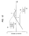
- This diagram apparently shows that the meniscus vibration at the orifice 61 is suppressed.
- a meniscus vibration at droplet charging causes defectives such as a change of a droplet volume, a deviation in a discharging direction, and an increase of satellites (extremely minute drops around the main drops), thereby lowering an image quality.
- reference numerals 300 and 302 designate an orifice and ink, respectively.
- a case in which no buffer chamber is provided is indicated by X and a case in which a buffer chamber is provided is indicated by Y.
- droplets are attached to a record medium in an order of cyan, magenta, and yellow by using the orifice strings in the left half of the base in the forward direction and droplets are attached to the record medium in an order of cyan, magenta, and yellow as well by using the orifice strings in the right half of the base in the backward direction, thereby achieving recording having no color-shading at all, and only one of the two orifice strings is used in the forward or backward direction for the yellow droplets, by which the non-printing orifices act as vibration suppressing elements, thereby realizing stable discharging.
- the pectinate grooves need not have the above dimensions necessarily if only it has a structure enabling an air to be kept stably. According to an investigation, it is found that air can be kept stably if only the length is at least 3 times a smaller one of the width and the height.
- the grooves may be disposed so that the meniscus vibration of each orifice is minimized and preferably the same number of grooves as for the liquid flow paths are disposed at the same pitch thereof.
- the buffer chambers 91 are preferably disposed so as to match the middle of adjacent liquid flow paths 60, in other words, with a difference by a half pitch from the arrangement of the liquid flow paths 60, so that two buffer chambers 91 equally act on a single liquid flow path 60. Furthermore, if the liquid flow paths 60 and the orifice plate 66 including the buffer chambers are formed in a process disclosed in Japanese Patent Laid-open Application No.
- disposing the buffer chambers 91 having the same shape as for the liquid flow paths 60 at regular intervals relative to the middle of the ink supplying apertures (through holes) improves parallelism of the vicinity surface of the orifices to the base surface when the base is coated with an orifice plate formation resin.
- the base is coated with a positive photosensitive resin, exposed and developed into shapes to be molds of the liquid flow paths 60 and the buffer chambers 91, and then coated with negative photosensitive resin so as to be optically hardened, and afterward the positive photosensitive resin is removed.
- the buffer chambers with apertures having communication with the orifice surface like the orifices. In this case, however, there is a need for providing a mechanism for removing mixed ink which might be caused by a penetration of adjacent ink. Additionally, if a cost does not increase due to an enlargement of the base, mixed ink can be eliminated by providing each chamber with an electrical heat converting element.
- grooves are formed to be buffer chambers 92 in parallel to the orifice 61 and liquid flow path 60 strings on the orifice plate 66 on the base 67, having a configuration in which the buffer chambers have communication with the ink supplying apertures 62 through communication slots 93 at several places.
- the groove has dimensions of 50 ⁇ m in width, 15 ⁇ m in height, and 5 mm in length, while the communication slot 93 has dimensions of 30 ⁇ m in width and 15 ⁇ m in height and they are disposed at 300 ⁇ m intervals.
- air is kept further stably, thereby securing a stability of discharging for a long period.
- the above groove is not limited to these dimensions, an oblong shape is preferable so as to keep a smaller base area.
- the number of the communication slots 93 if their quantity is too small, there are problems that an attenuation effect of the meniscus vibration is insufficient slot and that the attenuation effect depends upon a distance between the liquid flow path and the communication, and therefore it is preferable to provide a large number of communication slots.
- This section also describes only parts different from those of the configuration set forth in the first embodiment. Particularly, the description will be made by giving various examples of providing buffer chambers regarding the middle ink supplying aperture 62a for yellow.
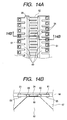
- Figs. 14A and 14B show modifications as a third embodiment of ink flow paths and their vicinity on the second recording element base 8 set forth in the first embodiment.
- grooves corresponding to liquid flow paths 60 are formed by providing a pectinate pattern on a nozzle formation member at the top of the middle ink supplying apertures 62 shown in Fig. 11 and buffer chambers 94 are formed by covering bottoms of all the grooves with a thin film member 95. This configuration assures a stability of discharging for, for example, yellow ink in the middle portion.
- the above groove has dimensions of 20 ⁇ m in width, 15 ⁇ m in height, and 50 ⁇ m in depth and there are provided buffer chambers 94 having openings in the opposite side to respective liquid flow paths 60 in both sides of the ink supplying apertures 62.
- buffer chambers 94a are formed with adjacent grooves connected with each other for communication, thereby reducing the number of the grooves to increase a mechanical strength of the nozzle formation member.
- buffer chambers 94b are formed by providing grooves parallel to an orifice string in addition to the example shown in Fig. 4, thereby enabling an air in the buffer chambers to be kept more stably.
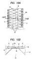
- buffer chambers 96 are formed by providing grooves parallel to an orifice 61 string on a nozzle formation member at the top of the middle ink supplying apertures 62 shown in Figs. 11A and 11B, covering these grooves with a thin film member 97, and providing apertures 97a at a desired pitch on the thin film member 97. This configuration enables a width of the buffer chamber and a base size to be minimized.
- FIG. 18 there is shown an explanatory diagram illustrating an example of a recording apparatus on which a liquid discharge recording head according to the present invention can be mounted.
- the head cartridge 1 shown in Fig. 1 is positioned and mounted on a carriage 102 so as to be exchangeable and the carriage 102 is provided with an electrically connected portion for transmitting a drive signal or the like to each discharging portion via an external signal input terminal (See the reference numeral 28 in Fig. 6) on the cartridge 1.
- the carriage 102 is guided and supported with being capable of a reciprocating motion along a guide shaft 103 installed in the apparatus with extending in the main scanning direction.
- the carriage 102 is driven via a driving mechanism including a motor pulley 105, a follower pulley 106, and a timing belt 107 and its position and movement are controlled by means of a main scanning motor 104.
- the carriage 102 is provided with a home position sensor 130. This enables the current position to be detected when the home position sensor 130 on the carriage 102 passes by a position of a shielding sheet 136.
- a record medium 108 such as a print form or a plastic thin plate is separated from others and fed one by one from an automatic sheet feeder (hereinafter, ASF) by rotating a pickup roller 131 via a gear from a feeding motor 135. Furthermore, a rotation of a carrying roller 109 delivers (vertical scanning) the medium after passing by the position (printed portion) opposite to an orifice surface of the head cartridge 1. The carrying roller 109 is rotated by a rotation of an LF motor 134 via a gear. In this operation, whether a sheet feed is completed is determined and a head location at the sheet feed is decided when the record medium 108 passes by a paper end sensor 133. Furthermore, the paper end sensor 133 is used to find where a rear end of the record medium 108 actually exists and to finally calculate the current recording position from the actual rear end.
- ASF automatic sheet feeder
- the record medium 8 is supported by a platen (not shown) on its rear surface so as to form a flat printing surface in the printed portion.
- the head cartridge 1 mounted on the carriage 102 is held so as to be parallel to the record medium 108 between two pairs of the carrying rollers with the orifice surface extruding downward from the carriage 102.
- the head cartridge 1 is mounted on the carriage 102 so that the orifices in each orifice portion are arranged in a direction crossing the scanning direction of the carriage 102 and is used for recording by discharging liquids from the orifice strings.
- a liquid discharge recording head comprises a plurality of strings of orifices corresponding to a plurality of recording liquids, a plurality of liquid flow paths and electrical heat converting elements corresponding to the plurality of orifice strings, and a plurality of liquid supplying apertures for supplying the liquids to the plurality of liquid flow path strings, wherein the colors of the liquids supplied to the liquid supplying apertures are arranged so that liquids having the same color are symmetrical about the middle of the head, by which the order of colors for discharging droplets onto medium is the same for recording in both of the forward and backward directions so as to prevent color-shading, thereby increasing a recording speed by applying bidirectional recording.
- liquid supplying apertures other than the middle one of the plurality of liquid supplying apertures for supplying liquids to the plurality of liquid flow path strings, orifice strings, heat resistance element strings, liquid flow path strings, and driver circuits so as to have line symmetry around the middle ink supplying aperture
- the liquid supplying apertures and the driver circuits can be disposed at regular intervals on the base efficiently, thus enabling a size of the base to be minimized.
- the reduction of the base size lowers a capacity of a memory for retaining transfer data to the recording head proportionally to the base size, thus enabling the cost to be lowered.
- buffer chambers are provided on the same plane as for the above liquid flow paths with being in contact with the liquid supplying apertures, air remains in the buffer chambers even in a condition in which the liquid supplying apertures and the liquid flow paths are filled with liquids, thereby enabling an attenuation of pressure fluctuations inside the liquid supplying apertures caused by discharging droplets. This reduces a meniscus vibration at driving a discharge, thereby enabling a high-quality image to be maintained.
Description
- The present invention relates to a liquid discharge recording head for applying a plurality of different colors of liquids such as ink to paper or other record mediums and a liquid discharge recording apparatus with the liquid discharge recording head mounted thereon for printing.
- A printer, particularly an ink-jet recording type printer is capable of outputting high-quality characters or images at low cost, thus rapidly spreading in office or home applications. Some products enable a black-character quality, a density, and a water resistance equivalent to those of commercial prints in text outputs. As far as images, there appeared products realizing colors and gradations equivalent to a silver gelatin (salt) print. In future, a lower cost and a high-speed output will be demanded as well as the above performances.
- Referring to Fig. 19, there is shown a perspective view partially exploded for an explanation of a configuration of a general color-ink-jet recording head. A
base 218 has three through holes (liquid supplying apertures) 219 formed thereon, to which ink of cyan, magenta, and yellow is supplied. The top surface of the base is covered with anozzle formation member 223, in which ink flow path strings are formed in contact with respective throughholes 219, electricalheat converting elements 220 are formed at the bottoms of the ink flow paths on the top surface of the base, andfurther orifices 224 are formed correspondingly to the electrical heat converting elements. In color recording by using an ink-jet recording head having this base, the head scans a record medium concurrently with attaching ink to the record medium in an order of cyan, magenta, and yellow and an image is formed by repeating this operation. While the head moves backward on the record medium, discharging in the arrangement order causes the order of colors to be reversed on the record medium and results in a hue change, thereby causing color-shading. Although it can be prevented by separating the arrangement order from the discharging order, it is not advantageous in high-speed recording. In addition, while it is necessary to increase a record frequency by increasing the number of orifices for high-speed recording, it increases an ink flow rate per unit time in the inside of the through hole and a pressure fluctuation in the inside thereof, thus giving unfavorable vibrations to a meniscus at the orifice. Particularly to increase the discharge frequency, there is a method of decreasing a flow path resistance, for example, by shortening the flow path to increase an ink moving speed in the ink flow path, while it also causes the vibrations of the meniscus at the orifice to be more sensitive to a pressure fluctuation inside the through hole. This problem will be serious in an area having a small droplet quantity of 10 pl (picoliters, 10 to 12 liters) or lower. -
US-A-4528526 describes a recording apparatus including a plurality of recorders each of which is provided for a colour to be recorded, these recorders being reciprocated relative to a recording medium such that they are selectively driven in combination upon their forward movement and in another combination upon the reverse movement of the recorders. -
EP-A-0955174 describes the achievement of a bidirectional color printing mode with colors applied in the same order regardless of the direction in which an ink jet pen is moving relative to a media sheet. -
EP-A-1110743 which published after the priority date of the present application and is therefore relevant for the purposes of novelty only under Article 543) describes a liquid ejection recording head for effecting recording by ejecting first and second different kinds of recording liquid through respective different ejection outlets while bidirectionally scanning the recording head relative to recording medium, wherein the liquid ejection recording head includes a first group of ejection outlet arrays arranged so that corresponding ejection outlets in the respective ejection arrays are aligned in the scanning direction and a second group of ejection outlets arrays arranged in a manner similar to the first ejection outlet array group, wherein the first ejection outlet arrays include a first ejection outlet array for ejecting the first liquid and a second ejection outlet array for ejecting the second liquid and the second ejection outlet array group includes a third ejection outlet array for ejecting the first liquid and a fourth ejection outlet array for ejecting the second liquid with the first ejection outlet array group and the second ejection outlet array group being disposed such that the first ejection outlet array and the third ejection outlet array are adjacent to one another and the ejection outlets of the first ejection outlet array and the ejection outlets of the third ejection outlet array are disposed with deviation in the direction in which the ejection outlets are arrayed so as to be complementary in the scanning direction. As shown in Figure 1 ofEP-A-1110743 , the outermost ejection array or column of each group is assigned to eject cyan recording liquid, the next ejection orifice columns are assigned to eject magenta color liquid and the inner ejection orifice arrays are assigned to eject yellow color liquid with the yellow color liquid being supplied to a centre ink supplying hole, magenta ink being supplied to corresponding magenta ink supplying holes and cyan ink being supplied to outermost ink supplying holes so that the centre ink supplying hole supplies two ejection orifices array with yellow color liquid. - According to a first aspect, the present invention providers a liquid discharge recording head as set out in
claim 1. - In an embodiment the present invention provides a liquid discharge recording head capable of providing high-speed color reciprocating printing free from color-shading in the minimum base size, wherein the recording head is a liquid discharge recording head capable of maintaining a high-quality image by attenuating a pressure fluctuation inside the liquid supplying aperture at the liquid discharge and to provide a liquid discharge recording apparatus having the recording head.
- In an embodiment, the color order for discharging droplets onto a record medium is the same for recording in both forward and backward direction, thereby preventing color-shading and reducing a pressure fluctuation inside the through holes effectively, by which high-speed bidirectional recording can be performed.
- In an embodiment the recording head preferably has an odd number of the liquid supplying apertures and an even number of the orifice strings, with the middle liquid supplying aperture among the plurality of liquid supplying apertures disposed between the orifices, the electrical heat (electro-thermal) conveting elements, and the liquid flow paths and with other liquid supplying apertures having orifices, electrical heat converting elements, and liquid flow paths in a single side of the other liquid supplying apertures.
- In this condition, the orifice strings (lines), the electrical heat converting elements, and the liquid flow paths are disposed almost line-symmetrically about the middle liquid supplying apertures.
- In this manner, by disposing the liquid supplying apertures other than the middle one among the plurality of liquid supplying apertures for supplying liquids to the plurality of liquid flow path strings (lines), the orifice strings, the heat resistance elements, the liquid flow paths, and driver circuits so as to have line symmetry about the middle ink supplying apertures, the liquid supplying apertures and the driver circuits can be disposed at regular intervals on the base efficiently, thus minimizing the base size. The reduction of the base size decreases a capacity of a memory for retaining transfer data to the recording head proportionally to the base size, thus enabling the cost to be lowered.
- Furthermore, in the above recording head, preferably the ith orifices counted from each end of the orifice strings belonging to a left half or a right half of the middle liquid supplying apertures are disposed on a single line and the ith orifice in the left half and the ith orifice in the right half are disposed with a difference by a half pitch in the column direction. This enables printing of high precision and fineness which is substantially twice those of the orifice array pitch.
- In a liquid discharge recording head embodying the invention air easily remains in the buffer chambers even in a condition in which the liquid supplying apertures and the liquid flow paths are filled with liquid , thereby enabling an attenuation of pressure fluctuations inside the liquid supplying apertures caused by discharging droplets. This reduces a meniscus vibration at driving a discharge, thereby enabling a high-quality image to be maintained.
- In this recording head, the number of the buffer chambers is preferably the same as the number of the liquid flow paths. In addition, preferably the pitch of adjacent buffer chambers is the same as a pitch of adjacent liquid flow paths and the buffer chambers are opposite to the liquid flow paths and disposed with a half-pitch difference relative to the liquid flow paths. The shape of the buffer chamber is preferably almost the same as that of the liquid flow path.
- Furthermore, preferably the plurality of liquid colors are at least the three colors of cyan, magenta, and yellow with the yellow liquid supplied to the middle liquid supplying aperture among the plurality of liquid supplying apertures.
- The buffer chambers may have communication with the liquid supplying apertures other than the middle liquid supplying aperture. In addition, the buffer chambers may form grooves each having a desired shape in a portion in contact with the middle liquid supplying aperture of a member forming the liquid flow paths and may be formed by covering these grooves with a thin film member.
- Furthermore, the liquid flow paths and the buffer chambers may be formed by coating the base with a positive photosensitive resin, exposing and developing it to shapes of molds of the liquid flow paths and the buffer chambers, coating it with a negative photosensitive resin, and then removing the positive photosensitive resin.
- In addition, the present invention provides a liquid discharge recording apparatus, which has a carriage for detachably mounting a liquid discharge recording head according to the first aspect, for recording on a record medium by discharging droplets from a desired orifice string of the liquid discharge recording head with a scanning of the carriage.
-
- Fig. 1 is a perspective view showing an example of a recording head cartridge to which the present invention is applicable;
- Fig. 2 is a perspective view showing a recording head and ink tanks forming the recording head cartridge in Fig. 1;
- Fig. 3 is an exploded perspective view of the recording head forming the recording head cartridge in Fig. 1;
- Fig. 4 is a detailed exploded perspective view of the recording head forming the recording head cartridge in Fig. 1;
- Fig. 5 is deleted.
- Fig. 6 is a cross section showing a connecting status of the recording head and the ink tanks shown in Fig. 2;
- Fig. 7 is a perspective view showing a connection status of the ink supplying unit and the recording element unit shown in Fig. 3;
- Fig. 8 is a perspective view showing a connection status of the ink supplying unit, the recording element unit, and the tank holder shown in Fig. 3;
- Figs. 9A, 9B, and 9C are diagrams of assistance in explaining a configuration of the second recording element base shown in Fig. 3;
- Figs. 10A and 10B are detail views showing ink flow paths coupled to ink supplying apertures other than the middle one and their surroundings on the second recording element base shown in Fig. 3;
- Figs. 11A and 11B are detail views showing ink flow paths coupled to ink supplying apertures other than the middle one and their surroundings on the second recording element base shown in Fig. 3;
- Fig. 12 is a graph showing a relation between a meniscus vibration observed when all the electrical heat converting elements (128 units) for cyan are driven at 15 kHz in the second recording element base shown in Fig. 3, for example, and a meniscus vibration in a conventional example for a comparison;
- Figs. 13A and 13B are diagrams showing modifications of the ink flow paths coupled to the ink supplying apertures other than the middle one on the second recording element base shown in Fig. 3 and its surroundings as a second embodiment of the present invention;
- Figs. 14A and 14B are diagrams showing modifications of the ink flow paths coupled to the ink supplying apertures other than the middle one on the second recording element base shown in Fig. 3 and its surroundings as a third embodiment of the present invention;
- Figs. 15A and 15B are diagrams showing modifications of the embodiment shown in Figs. 14A and 14B;
- Figs. 16A and 16B are diagrams showing further modifications of the buffer chambers shown in Figs. 15A and 15B;
- Figs. 17A and 17B are diagrams other modifications of the embodiment shown in Figs. 14A and 14B;
- Fig. 18 is an explanatory diagram showing an example of a recording apparatus on which a liquid discharge recording head according to the present invention can be mounted; and
- Fig. 19 is a configuration diagram of a general color-ink-jet recording head.
- The preferred embodiments of the present invention will now be described hereinafter with reference to the accompanying drawings.
- Referring to Fig. 1 to Fig. 8, there are shown explanatory diagrams for describing preferred head cartridges, recording heads, and ink tanks and their relations according to the present invention, respectively. Hereinafter, their components will be described on the basis of these drawings.
- As shown in Fig. 1 and Fig. 2, a
recording head cartridge 1 according to this embodiment comprises arecording head 2 and ink tanks 3 (3a, 3b, 3c, and 3d) detachably mounted on therecording head 2. Thisrecording head cartridge 1 is fixed and supported by a positioning unit of a carriage (not shown) mounted on an ink-jet recording apparatus and electrical contacts and detachably mounted on the carriage. Theink tanks ink tanks recording head unit 2, so that each of the ink tanks is exchangeable, thus reducing a running cost of printing in the ink-jet recording apparatus. - Next, the
recording head 2 is described in more detail by giving an explanation of components forming the recording head in order. - For the
recording head 2, there is used a recording head which is a side shooter type in a bubble-jet process for recording by using electrical heat converting elements for generating heat energy causing film boiling in response to an electric signal on ink. As shown in exploded perspective views in Fig. 3 and Fig 4, therecording head 2 comprises arecording element unit 4, anink supplying unit 5, and atank holder 6. - The
recording element unit 4 comprises a firstrecording element base 7, a secondrecording element base 8, afirst plate 9, anelectrical wiring tape 10, anelectrical contact base 11, and asecond plate 12 and theink supplying unit 5 comprises anink supplying member 13, a flowpath forming member 14, ajoint rubber 15, afilter 16, and aseal rubber 17. - The second
recording element base 8, which will be described in detail later, is a recording element base for discharging ink of three colors with the ink supplying apertures formed in parallel and with each of the ink supplying apertures between strings of the electrical heat converting elements and the ink orifices Naturally in the same manner as for the first recording element base, ink supplying apertures, electrical heat converting elements, electrical wiring, and electrode portions are formed on an Si base and ink flow paths and ink orifices are formed thereon by a resin material in the photolithography technology. - Additionally in the same manner as for the first
recording element base 7, Au or other bumps are formed in theelectrode portions 1 for supplying power to the electrical wiring. The first plate 9 (see Figure 4) is made of, for example, an aluminum oxide (Al2O3) material having a thickness of 0.5 to 10 mm. The material of thefirst plate 9 is not limited to the aluminum oxide, but may be a material having a linear expansion coefficient equivalent to that of the material of therecording element base recording element base first plate 9 can be any of silicon (Si), aluminum nitride (AlN), zirconium oxide, silicon nitride (Si3N4), silicon carbide (SiC), molybdenum (Mo), and tungsten (W). Thefirst plate 9 hasink supplying apertures 26 for supplying a black ink to the firstrecording element base 7 andink supplying apertures 26 for supplying ink of cyan, magenta, and yellow to the secondrecording element base 8 formed on the first plate, and the ink supplying apertures 19 on therecording element bases ink supplying apertures 26 on thefirst plate 9, respectively, and the firstrecording element base 7 and the secondrecording element base 8 are bonded to be fixed to thefirst plate 9 at a high positional precision, respectively. Preferably a first adhesive used for the bonding has a low viscosity, a low hardening temperature so as to be hardened in a short time, relatively high hardness after the hardening, and a resistance to ink. The first adhesive is preferably, for example, a heat-hardening adhesive whose principal element is, for example, an epoxy and the thickness of its bonding layer is 50 µm or lower. - The
electrical wiring tape 10 is used for applying an electric signal for discharging ink to the first recording element base7 and the secondrecording element base 8 and comprises a plurality of opening portions for incorporating the recording element bases,electrode terminals 27 corresponding to the electrode portions of the recording element bases, and anelectrode terminal portion 29, which is located in an end portion of thewiring tape 10, for an electrical connection with theelectrical contact base 11 having an externalsignal input terminal 28 for receiving the electric signal from the apparatus, with theelectrode terminal 27 connected to theelectrode terminal portion 29 through a continuous copper foil wiring pattern. - The
electrical wiring tape 10, the firstrecording element base 7, and the secondrecording element base 8 are electrically connected to each other in such a way, for example, that theelectrode portion 21 of the recording element base is electrically joined to theelectrode terminal 27 on theelectrical wiring tape 10 in the heat ultrasonic contact bonding process. - The
second plate 12 is, for example, a sheet of plate member having a thickness of 0.5 to 1 mm and is made of, for example, aluminum oxide (Al2O3) or other ceramic or Al, SUS, or other metallic materials. Additionally it has opening portions larger than external dimensions of the firstrecording element base 7 and the second recordingelement recording base 8 bonded and fixed to thefirst plate 9. Furthermore, the firstrecording element base 7, the secondrecording element base 8, and theelectrical wiring tape 10 are bonded to thefirst plate 9 with a second adhesive so that they can be electrically connected to each other on a plane and a back of theelectrical wiring tape 10 is bonded and fixed with a third adhesive. - The electrically connected portions between the first
recording element base 7, the secondrecording element base 8, and theelectrical wiring tape 10 are sealed by a first sealer and a second sealer (not shown) to protect the electrically connected portions from a corrosion caused by ink or an external shock. The first sealer is mainly used for sealing in the rear of the connected portion between theelectrode terminal 27 of theelectrical wiring tape 10 and theelectrode portion 21 of the recording element base and in the outer peripheral portion and the second sealer is used for sealing in the face of the connected portion. Furthermore, theelectrical contact base 11 having the externalsignal Kaput terminal 28 for receiving an electric signal from the apparatus at the end of theelectrical wiring tape 10 is electrically connected by heat contact bonding using an anisotropic conductive film or the like. - Then, the
electrical wiring tape 10 is folded in a single side of thefirst plate 9 and bonded by the third adhesive on the side of thefirst plate 9. The third adhesive is, for example, a heat-hardening adhesive having a thickness of 10 to 100 µm whose principal element is an epoxy. - The
ink supplying member 13 is formed by, for example, a resin mold. The resin material preferably contains glass filler by 5 to 40 % to increase rigidity in shape. - As shown in Fig. 3, Fig. 4, and Fig. 6, the
ink supplying member 13 is a component of theink supplying unit 5 for guiding ink from theink tank 3 to therecording element unit 4, withink flow paths 32 formed by ultrasonic solvent welding of the flowpath forming member 14. Ajoint portion 33 for engaging with theink tank 3 is jointed to afilter 34 to prevent a mixture of rubbish from the outside and further aseal rubber 35 is mounted to prevent ink from evaporating from thejoint portion 33. - In addition, the
ink supplying member 13 partially has a function of holding the detachably-mountedink tank 3, thus having afirst aperture 37 for an engagement of asecond click 36 of theink tank 3. - The
ink supplying member 13 comprises a mountingguide 38 for guiding therecording head cartridge 1 to a mounting position of the carriage (not shown) of the ink-jet recording apparatus, an engagingportion 39 for mounting and fixing therecording head cartridge 1 to the carriage (not shown) by a headset lever, a buttingportion 40 in an X direction (in the carriage scanning direction) for positioning in a predetermined mounting position of the carriage, a buttingportion 41 in a Y direction (in the recording media conveying direction), and a buttingportion 42 in a Z direction (in the ink discharge direction). Additionally, it has aterminal fixing portion 43 for positioning and fixing theelectrical contact base 11 of therecording element unit 4, with a plurality of ribs provided in theterminal fixing portion 43 and its surroundings to increase rigidity of a surface having theterminal fixing portion 43. - As shown in Fig. 3 in the above, the
recording head 2 is completed by connecting therecording element unit 4 to theink supplying unit 5 and further to thetank holder 6. They are connected as described below. - An ink supplying aperture (the
ink supplying aperture 26 of the first plate 9) of therecording element unit 4 and an ink supplying aperture (theink supplying aperture 44 of the flow path forming member 14) of theink supplying unit 5 are fixed withmachine screws 45 via ajoint rubber 15 so that these members are contact-bonded in order to enable the members to have communication with each other, being free from a leakage of ink. Simultaneously with this fixing, therecording element unit 4 is accurately positioned and fixed at the reference position in the X, Y, and Z directions of theink supplying unit 5. - Then, the
electrical contact base 11 of therecording element unit 4 is positioned and fixed to a single side of theink supplying member 13 by terminal positioning pins 46 (two places) and terminal positioning holes 47 (two places). Regarding the fixing method, for example, theelectrical contact base 11 is fixed by passingterminal connecting pins 48 provided on theink supplying member 13 throughterminal connecting holes 49 before caulking, while other fixing means can be used for fixing the base. A completed view is shown in Fig. 6. - Furthermore, a connection hole and a connected portion to the
tank holder 6 of theink supplying member 13 are fitted and connected to thetank holder 6, by which therecording head 2 is completed. The completed view is shown in Fig. 7. - The above Fig. 1 and Fig. 2 are explanatory diagrams of mounting the
recording head 2 and theink tanks recording head cartridge 1, with the corresponding color ink contained in theink tanks ink supplying aperture 50 for supplying the ink in the ink tank to therecording head 2. For example, when theink tank 3 is mounted on therecording head 2, theink supplying aperture 50 of theink tank 3 is contacted with a pressure to thefilter 34 provided in thejoint portion 33 of therecording head 2, by which the black ink in theink tank 3 is supplied to therecording element base 7 passing through thefirst plate 9 via theink flow path 32 of therecording head 2 from theink supplying aperture 50. - Then, the ink is supplied to a bubble chamber having the electrical heat converting elements 20 and the orifices 24 and then discharged toward a recording sheet which is a record medium by a heat energy given to the electrical heat converting elements 20.
- Subsequently, the second
recording element base 8 is described in detail below. Referring to Figs. 9A and 9B, there are shown plan views each showing a configuration of the secondrecording element base 8. Typically as shown in Fig. 9C, the secondrecording element base 8 comprises a base 67 including heatresistive elements 65 as energy converting elements and anorifice plate 66 for formingorifices 61. Thebase 67 is made of a silicon single crystal of a plane direction <100>. On thebase 67, there are formed a plurality of strings (lines) of the heatresistive elements 65, transistors orother driver circuits 63 for driving the strings of the heatresistive elements 65, acontact pad 69 for a connection with the outside, andwiring 68 for connecting thedriver circuits 63 to thecontact pad 69 by using a semiconductor process. - The
orifice plate 66 provided on theplate 67 is made of a photosensitive epoxy, theorifices 61 and theliquid flow paths 60 are formed correspondingly to the heatresistive elements 65 in a process as disclosed inJapanese Patent Laid-open Application No. 62-264957 above circuits 63,elements 65, andwiring 68 on thebase 67, there are provided five through holes formed by anisotropic etching as disclosed inJapanese Patent Laid-open Application No. 9-11479 ink supplying apertures ink supplying apertures path forming member 14 of the ink supplying unit shown in Fig. 3. -
Orifice 61 strings, heatresistive element 65 strings, andliquid flow path 60 strings are disposed on both side of the middleink supplying aperture 62a and aorifice 61 string, a heatresistive element 65 string, and aliquid flow path 60 string are disposed in a single side of each of otherink supplying apertures 62. Furthermore, the ink supplying aperture and orifice strings, the heat resistive element strings, the liquid flow path strings, and the driver circuits other than the middle ones are disposed so as to be in a positional relationship between the left side and the right side of the base having a line of symmetry through the middleink supplying apertures 62a (in other words, a relation of reflective symmetry). This arrangement enables the ink supplying apertures (through holes) and the driver circuits to be disposed on the base at regular intervals efficiently, thus achieving the minimum base size. In this embodiment, the total width of the nozzle, the driving transistor, and the wiring is 1.2 mm, a width of the through hole is 0.2 mm, and the base size is 1.2 × 6 + 0.2 × 5 = 8.2 mm. On the other hand, on therecording element base 7 for black ink as shown in Fig. 4, a single through hole is provided for a base and two orifice strings are disposed. The base size in this condition is 1.2 × 2 + 0.2 = 2.6 mm, and therefore if six sheets are used for a base for color ink as described in this embodiment, the base size is 2.6 × 6 = 15.6 mm. Even if a single orifice string is used instead of two strings, a size for a through hole formation is required and thus the base size cannot be reduced. The colorrecording element base 8 in this embodiment enables a capacity of a memory for retaining transfer data to the recording head to be reduced in proportion to the base size by decreasing the base size, thereby enabling the cost to be lowered. - In addition, six orifice strings (discharging portions) 71 to 73 and 81 to 83 almost parallel with each other are formed on the top surface of the
recording element base 8 and the orifice strings 73, 72, 71, 81, 82, and 83 are used for discharging liquids of cyan, magenta, yellow, yellow, magenta, and cyan in this order, respectively. In this condition, in Fig. 9A, the ith orifices of the orifice strings 71 to 73 counted from the top of the drawing coincide with each other in a direction indicated by an arrow shown in Fig. 9A. In this manner, in a scanning direction in which the recording elements are scanned with being mounted on a recording apparatus described later, the orifice strings 71 to 73 are arranged so that the corresponding orifices coincide with each other and thus a firstorifice string group 70 is formed. The orifice strings 81 to 83 are arranged in the same manner s for the orifice strings 71 to 73, and a secondorifice string group 80 is formed by the orifice strings 81 to 83 so as to be adjacent to the fistorifice string group 70. - The first
orifice string group 70 and the secondorifice string group 80 are arranged with a difference of just a half of the orifice array pitch in a vertical scanning direction (in this embodiment, coinciding with an arrangement direction of the orifice strings) of the recording head so that respective orifices of the orifice strings 71 to 73 and 81 to 83 forming respective orifice groups complement each other in the scanning direction. This enables printing of high precision and fineness which is substantially twice that of the orifice array pitch. - Additionally, the
recording element base 8 is capable of receiving a drive signal or the like from the recording apparatus when an external signal input terminal (see thereference numeral 28 in Fig. 7) coupled to this wiring plate is connected to an electrically connected portion of the recording apparatus by connecting thecontact pad 69 to the electrode terminal (see thereference numeral 27 in Fig. 3) on theelectrical wiring tape 10. - Subsequently, a recording method with this
recording element base 8 is described below. In this embodiment, assuming that the heat emitting resistor has a size of 30 µm × 30 µm, 128 heat emitting resistors are disposed for a single orifice string at 600 dpi and approx. 8 pl of ink is discharged from each nozzle (orifice) for recording. Two types of recording modes are used for the recording; a high-speed mode and a high resolution mode. - In the high-speed mode, a binary mode of 600 dpi is used for the recording in order to save time for image processing and data transfer. In this mode, two droplets are discharged for a single picture element (600 x 600 dpi) for printing a single color. Supposing that the nozzle strings are referred to as C1, M1, Y1, Y2, M2, and C2, for example, a droplet is discharged from each of the C1 and C2 nozzles to form an image for recording with cyan. Next, for printing of a secondary color, for example, green (G), a droplet is discharged from each nozzle of the C1, Y1, Y2, and C2 strings for a single picture element to form an image. For recording in the forward direction in the above, ink is attached to a record medium in an order of C(1), Y(1), Y(2), and C(2). For recording in the backward direction, ink is attached to the record medium in an order of C(2), Y(2), Y(1), and C(1). In both direction of the reciprocation, the attachment order of the ink is the same (CYYC), thus preventing color-shading from being caused by the reciprocation.
- Next, in the high resolution mode, a single droplet is discharged for a single picture element (600 × 1200 dpi) for printing in a single color. First, an image area is masked and then picture elements for recording with a C1, M1, and Y1 nozzle string set are separated from picture elements for recording with a C2, M2, and Y2 nozzle string set before printing. For example, for printing in green, there are two types of picture elements mixed; picture elements for recording in C1 and Y1 (attached to paper in an order of C and Y) and those for recording in C2 and Y2 (attached to paper in an order of Y and C), though the color-shading is at an unnoticeable level due to uniform scattering of the picture elements.
- As set forth in the above, a plurality of m nozzle strings (in this embodiment, m = 6) are formed in parallel and there is a relation of m = n + 1 where n designates the number of the plurality of supplying paths (in this embodiment, n = 5), by which it becomes possible to provide color reciprocating color printing free from color-shading at a high speed and with the minimum head size. Furthermore, in this embodiment there is an effect of an easy control of printing timing since distances between adjacent nozzle strings are almost fixed. While three colors of C, M, and Y are used in this embodiment, the same effect is achieved when light cyan or light magenta is further added.
- Furthermore, referring to Figs. 10A and 10B and Figs. 11A and 11B, there are shown ink flow paths and their surroundings on the second
recording element base 8. More specifically, Fig. 10A, Fig. 10B, Fig. 11A, and Fig. 11B show a perspective diagram around theink supplying aperture 62 other than the middle one on thebase 8 in Fig. 8, a sectional view taken online 10B-10B of Fig. 10A, a perspective diagram around the middleink supplying aperture 62a on thebase 8 in Fig. 8, and a sectional view taken online 11B-11B of Fig. 11A, respectively. Referring to these drawings, the electricalheat converting elements 65 are formed on a surface of thebase 67 and further a nozzle formation member made of a transparent resin to be anorifice plate 66 covers almost the entire surface of the base 67 including theink supplying apertures 62. At an edge of the top of theink supplying aperture 62 in the side of theliquid flow path 60, a nozzle formation member is hollowed so that theink supplying aperture 62 has communication with theliquid flow path 60. On the other hand, at an edge of the top of theink supplying aperture 62 in the opposite side of theflow path 60, the nozzle formation member is hollowed so as to form pectinate grooves asbuffer chambers 91. Regarding the middleink supplying aperture 62a shown in Fig. 9c, however, the nozzle formation member is hollowed so as to have communication with theliquid flow path 60 strings in the both sides. The shape of thebuffer chambers 91 are almost the same as that of the pectinateliquid flow paths 60 composed of a plurality of strings. Assuming that the pectinate groove has dimensions of 30 µm in width, 15 µm in height, and 50 µm in length, the pectinate groove string to be thebuffer chambers 91 is arranged with a difference by a half pitch from the opposite liquid flow path string at 600 dpi as shown in Fig. 10A. The term "chamber" is used for meaning that it has closed portions except the portion having communication with the ink supplying apertures. - In this configuration, air remains in the pectinate grooves as buffer chambers even if the
ink supplying apertures 62 and theliquid flow paths 60 are filled with ink by providing thebuffer chambers 91 in the opposite side to the orifice string with each ink supplyingaperture string 72 therebetween, thereby attenuating pressure fluctuations inside theink supplying apertures 62 caused by discharging droplets. - Referring to Fig. 12, in the
recording element base 8 in this embodiment, there are shown a meniscus vibration generated when, for example, all the electrical heat converting elements (128 elements) for cyan are driven at 15 kHz and another meniscus vibration in the conventional apparatus for a comparison. In Fig. 12, there is also shown a meniscus vibration (Z) generated when only a single electrical heat converting element is driven in this embodiment. This diagram apparently shows that the meniscus vibration at theorifice 61 is suppressed. A meniscus vibration at droplet charging causes defectives such as a change of a droplet volume, a deviation in a discharging direction, and an increase of satellites (extremely minute drops around the main drops), thereby lowering an image quality. In this embodiment, however, an image keeps a high quality by the suppression of the meniscus vibration. In this diagram,reference numerals - For the middle
ink supplying aperture 62a for yellow, there is not provided anybuffer chamber 91, but a favorable image quality is achieved since yellow is visually unnoticeable regarding a change of an image in comparison with cyan and magenta. - Furthermore, in a third printing mode beside the above printing modes, droplets are attached to a record medium in an order of cyan, magenta, and yellow by using the orifice strings in the left half of the base in the forward direction and droplets are attached to the record medium in an order of cyan, magenta, and yellow as well by using the orifice strings in the right half of the base in the backward direction, thereby achieving recording having no color-shading at all, and only one of the two orifice strings is used in the forward or backward direction for the yellow droplets, by which the non-printing orifices act as vibration suppressing elements, thereby realizing stable discharging.
- The pectinate grooves need not have the above dimensions necessarily if only it has a structure enabling an air to be kept stably. According to an investigation, it is found that air can be kept stably if only the length is at least 3 times a smaller one of the width and the height. In addition, as for the number of grooves and its disposition pitch, the grooves may be disposed so that the meniscus vibration of each orifice is minimized and preferably the same number of grooves as for the liquid flow paths are disposed at the same pitch thereof. In addition, taking into consideration a case in which air cannot be kept in the
buffer chamber 91 or in which the buffer chamber cannot work normally due to dust clogging, thebuffer chambers 91 are preferably disposed so as to match the middle of adjacentliquid flow paths 60, in other words, with a difference by a half pitch from the arrangement of theliquid flow paths 60, so that twobuffer chambers 91 equally act on a singleliquid flow path 60. Furthermore, if theliquid flow paths 60 and theorifice plate 66 including the buffer chambers are formed in a process disclosed inJapanese Patent Laid-open Application No. 62-264957 buffer chambers 91 having the same shape as for theliquid flow paths 60 at regular intervals relative to the middle of the ink supplying apertures (through holes) improves parallelism of the vicinity surface of the orifices to the base surface when the base is coated with an orifice plate formation resin. As for a formation method of theliquid flow paths 60 and thebuffer chambers 91, the base is coated with a positive photosensitive resin, exposed and developed into shapes to be molds of theliquid flow paths 60 and thebuffer chambers 91, and then coated with negative photosensitive resin so as to be optically hardened, and afterward the positive photosensitive resin is removed. - It is also possible to provide the buffer chambers with apertures having communication with the orifice surface like the orifices. In this case, however, there is a need for providing a mechanism for removing mixed ink which might be caused by a penetration of adjacent ink. Additionally, if a cost does not increase due to an enlargement of the base, mixed ink can be eliminated by providing each chamber with an electrical heat converting element.
- This section describes only parts different from those of the configuration set forth in the first embodiment.
- Referring to Figs. 13A and 13B, there are shown modifications of the ink flow paths and their vicinity on the second
recording element base 8 set forth in the above. In this embodiment, grooves are formed to bebuffer chambers 92 in parallel to theorifice 61 andliquid flow path 60 strings on theorifice plate 66 on thebase 67, having a configuration in which the buffer chambers have communication with theink supplying apertures 62 throughcommunication slots 93 at several places. The groove has dimensions of 50 µm in width, 15 µm in height, and 5 mm in length, while thecommunication slot 93 has dimensions of 30 µm in width and 15 µm in height and they are disposed at 300 µm intervals. According to this embodiment, air is kept further stably, thereby securing a stability of discharging for a long period. Although the above groove is not limited to these dimensions, an oblong shape is preferable so as to keep a smaller base area. As for the number of thecommunication slots 93, if their quantity is too small, there are problems that an attenuation effect of the meniscus vibration is insufficient slot and that the attenuation effect depends upon a distance between the liquid flow path and the communication, and therefore it is preferable to provide a large number of communication slots. - This section also describes only parts different from those of the configuration set forth in the first embodiment. Particularly, the description will be made by giving various examples of providing buffer chambers regarding the middle
ink supplying aperture 62a for yellow. - Figs. 14A and 14B show modifications as a third embodiment of ink flow paths and their vicinity on the second
recording element base 8 set forth in the first embodiment. In this embodiment, grooves corresponding toliquid flow paths 60 are formed by providing a pectinate pattern on a nozzle formation member at the top of the middleink supplying apertures 62 shown in Fig. 11 andbuffer chambers 94 are formed by covering bottoms of all the grooves with athin film member 95. This configuration assures a stability of discharging for, for example, yellow ink in the middle portion. For example, the above groove has dimensions of 20 µm in width, 15 µm in height, and 50 µm in depth and there are providedbuffer chambers 94 having openings in the opposite side to respectiveliquid flow paths 60 in both sides of theink supplying apertures 62. - Referring to Figs. 15A and 15B, there are shown modifications of the above embodiment. In examples shown in these diagrams,
buffer chambers 94a are formed with adjacent grooves connected with each other for communication, thereby reducing the number of the grooves to increase a mechanical strength of the nozzle formation member. - Referring to Figs. 16A and 16B, there are shown further modifications of the buffer chambers shown in Figs. 15A and 15B. In examples shown in these diagrams,
buffer chambers 94b are formed by providing grooves parallel to an orifice string in addition to the example shown in Fig. 4, thereby enabling an air in the buffer chambers to be kept more stably. - Referring to Figs. 17A and 17B, there are shown other modifications of the embodiment shown in Figs. 14A and 14B. In an example shown in this diagram,
buffer chambers 96 are formed by providing grooves parallel to anorifice 61 string on a nozzle formation member at the top of the middleink supplying apertures 62 shown in Figs. 11A and 11B, covering these grooves with athin film member 97, and providingapertures 97a at a desired pitch on thethin film member 97. This configuration enables a width of the buffer chamber and a base size to be minimized. - Finally, a description will be made for a liquid discharge recording apparatus on which the above cartridge type recording head can be mounted. Referring to Fig. 18, there is shown an explanatory diagram illustrating an example of a recording apparatus on which a liquid discharge recording head according to the present invention can be mounted.
- In the recording apparatus shown in Fig. 18, the
head cartridge 1 shown in Fig. 1 is positioned and mounted on acarriage 102 so as to be exchangeable and thecarriage 102 is provided with an electrically connected portion for transmitting a drive signal or the like to each discharging portion via an external signal input terminal (See thereference numeral 28 in Fig. 6) on thecartridge 1. - The
carriage 102 is guided and supported with being capable of a reciprocating motion along aguide shaft 103 installed in the apparatus with extending in the main scanning direction. Thecarriage 102 is driven via a driving mechanism including amotor pulley 105, afollower pulley 106, and atiming belt 107 and its position and movement are controlled by means of amain scanning motor 104. In addition, thecarriage 102 is provided with ahome position sensor 130. This enables the current position to be detected when thehome position sensor 130 on thecarriage 102 passes by a position of ashielding sheet 136. - A
record medium 108 such as a print form or a plastic thin plate is separated from others and fed one by one from an automatic sheet feeder (hereinafter, ASF) by rotating apickup roller 131 via a gear from a feedingmotor 135. Furthermore, a rotation of a carryingroller 109 delivers (vertical scanning) the medium after passing by the position (printed portion) opposite to an orifice surface of thehead cartridge 1. The carryingroller 109 is rotated by a rotation of anLF motor 134 via a gear. In this operation, whether a sheet feed is completed is determined and a head location at the sheet feed is decided when therecord medium 108 passes by apaper end sensor 133. Furthermore, thepaper end sensor 133 is used to find where a rear end of therecord medium 108 actually exists and to finally calculate the current recording position from the actual rear end. - The
record medium 8 is supported by a platen (not shown) on its rear surface so as to form a flat printing surface in the printed portion. In this embodiment, thehead cartridge 1 mounted on thecarriage 102 is held so as to be parallel to therecord medium 108 between two pairs of the carrying rollers with the orifice surface extruding downward from thecarriage 102. - The
head cartridge 1 is mounted on thecarriage 102 so that the orifices in each orifice portion are arranged in a direction crossing the scanning direction of thecarriage 102 and is used for recording by discharging liquids from the orifice strings. - As set forth hereinabove, a liquid discharge recording head comprises a plurality of strings of orifices corresponding to a plurality of recording liquids, a plurality of liquid flow paths and electrical heat converting elements corresponding to the plurality of orifice strings, and a plurality of liquid supplying apertures for supplying the liquids to the plurality of liquid flow path strings, wherein the colors of the liquids supplied to the liquid supplying apertures are arranged so that liquids having the same color are symmetrical about the middle of the head, by which the order of colors for discharging droplets onto medium is the same for recording in both of the forward and backward directions so as to prevent color-shading, thereby increasing a recording speed by applying bidirectional recording.
- In addition, by disposing liquid supplying apertures other than the middle one of the plurality of liquid supplying apertures for supplying liquids to the plurality of liquid flow path strings, orifice strings, heat resistance element strings, liquid flow path strings, and driver circuits so as to have line symmetry around the middle ink supplying aperture, the liquid supplying apertures and the driver circuits can be disposed at regular intervals on the base efficiently, thus enabling a size of the base to be minimized. The reduction of the base size lowers a capacity of a memory for retaining transfer data to the recording head proportionally to the base size, thus enabling the cost to be lowered.
- Particularly, as buffer chambers are provided on the same plane as for the above liquid flow paths with being in contact with the liquid supplying apertures, air remains in the buffer chambers even in a condition in which the liquid supplying apertures and the liquid flow paths are filled with liquids, thereby enabling an attenuation of pressure fluctuations inside the liquid supplying apertures caused by discharging droplets. This reduces a meniscus vibration at driving a discharge, thereby enabling a high-quality image to be maintained.
Claims (15)
- A liquid discharge recording head for carrying out a recording operation by discharging colour recording liquids on to a recording medium during relative movement in a scanning direction between the recording head and the recording medium, the recording head comprising:a plurality of substantially parallel lines (71 to 73, 81 to 83) of discharge orifices, each discharge orifice (61) being coupled to a corresponding liquid flow path (60) and being associated with an electro-thermal converting element (65) for causing discharge of liquid from the discharge orifice; anda plurality of liquid supply apertures (62, 62a) arranged along the discharge orifice lines (71 to 73 and 81 to 83) for supplying a plurality of colours of recording liquid, each liquid supply aperture being coupled to a plurality of the liquid flow paths so as to cause the same colour recording liquid to be supplied to the discharge orifices in the same discharge orifice line, wherein, for at least some of the discharge orifice lines (72, 73, 82 and 83), the corresponding liquid supply aperture is provided on one side of the discharge orifice line and the liquid flow path associated with that discharge orifice line communicate with a buffer chamber (91, 92) provided at an edge of the top of the liquid supply aperture in the opposite side of the flow path to attenuate pressure fluctuations resulting from liquid discharge.
- A liquid discharge recording head according to claim 1, comprising an odd number of said liquid supplying apertures (62, 62a) and an even number of said discharge orifice lines (71 to 73, 81 to 83), wherein the middle liquid supplying apertures (62a) of said plurality of liquid supplying apertures is disposed between the orifices lines, the electro-thermal converting elements (65), and the liquid flow paths and wherein the other liquid supplying apertures (62) are disposed with the orifice lines, electro-thermal converting elements (65), and liquid flow paths arranged on one side of those liquid supplying apertures (62).
- A liquid discharge recording head according to claim 2, wherein said discharge orifice lines (71 to 73, 81 to 83) are almost line-symmetrically arranged about the middle liquid supplying aperture (62).
- A liquid discharge recording head according to claim 3, wherein the ith orifices counted from each end of said orifice lines belonging to a left half or a right half of the middle liquid supplying aperture (62a) are disposed on a single line and the ith orifice in the left half and the ith orifice in the right half are disposed with a half pitch difference in the orifice line direction.
- A liquid discharge recording head according to any preceding claim, wherein a driver circuit is provided for controlling driving of each electro-thermal converting element corresponding to a said discharge orifice line.
- A liquid discharge recording head according to any of the preceding claims, wherein the number of the buffer chambers (91, 92) is equal to the number of said liquid flow paths.
- A liquid discharge recording head according to claim 6, wherein the pitch of adjacent said buffer chambers is the same as the pitch of adjacent said liquid flow paths and said buffer chambers (91, 92) are opposite to said liquid flow paths and disposed with a half-pitch difference relative to said liquid flow paths.
- A liquid discharge recording head according to claim 7, wherein the shape of said buffer chambers is almost the same as that of said liquid flow paths.
- A liquid discharge recording head according to any of claims 1 to 8, wherein the recording head is arranged to record using as said plurality of recording liquid colors at least cyan, magenta, and yellow and the yellow color liquid is supplied to the middle liquid supplying aperture (62a) among the plurality of liquid supplying apertures.
- A liquid discharge recording head according to any of the preceding claims, wherein said buffer chambers (91,92) communicate with the liquid supplying apertures (62a) other than the middle liquid supplying aperture (62a).
- A liquid discharge recording head according to any preceding claims, wherein the buffer chambers define a pectinate arrangement.
- A liquid discharge recording head according to any of claims 1 to 10, wherein the buffer chambers communicate with the ink supplying apertures through communication slots.
- A liquid discharge recording head according to any of the preceding claims, wherein said buffer chambers comprise grooves covered with a thin film member, each groove having a desired shape in a portion in contact with the middle liquid supplying aperture (62a) provided in a member forming said liquid flow paths.
- A method of manufacturing a liquid discharge recording head according to any of the preceding claims, wherein said liquid flow paths and said buffer chambers are formed by coating a base with a positive photosensitive resin, exposing and developing the resist to form molds for said liquid flow paths and said buffer chambers, coating the developing resist with a negative photosensitive resin, and then removing said positive photosensitive resin.
- A liquid discharge recording apparatus having a liquid discharge recording head according to any of claims 1 to 13 detachably mounted to a carriage for recording on a recording medium by discharging droplets from an orifice line of the liquid discharge recording head while the carriage is scanned relative to the recording medium.
Applications Claiming Priority (2)
| Application Number | Priority Date | Filing Date | Title |
|---|---|---|---|
| JP2000209091 | 2000-07-10 | ||
| JP2000209091 | 2000-07-10 |
Publications (2)
| Publication Number | Publication Date |
|---|---|
| EP1177903A1 EP1177903A1 (en) | 2002-02-06 |
| EP1177903B1 true EP1177903B1 (en) | 2007-06-27 |
Family
ID=18705556
Family Applications (1)
| Application Number | Title | Priority Date | Filing Date |
|---|---|---|---|
| EP01305894A Expired - Lifetime EP1177903B1 (en) | 2000-07-10 | 2001-07-09 | Liquid discharge recording head and liquid discharge recording apparatus |
Country Status (3)
| Country | Link |
|---|---|
| US (1) | US6575560B2 (en) |
| EP (1) | EP1177903B1 (en) |
| DE (1) | DE60129080T2 (en) |
Families Citing this family (15)
| Publication number | Priority date | Publication date | Assignee | Title |
|---|---|---|---|---|
| JP2004001490A (en) * | 2002-04-23 | 2004-01-08 | Canon Inc | Inkjet head |
| JP4236250B2 (en) * | 2002-04-23 | 2009-03-11 | キヤノン株式会社 | Inkjet head |
| JP4236251B2 (en) * | 2002-04-23 | 2009-03-11 | キヤノン株式会社 | Inkjet head |
| US7410241B2 (en) * | 2004-09-13 | 2008-08-12 | Canon Kabushiki Kaisha | Ink jet head, ink jet printer and method for manufacturing ink jet head |
| JP4724490B2 (en) * | 2005-08-09 | 2011-07-13 | キヤノン株式会社 | Liquid discharge head |
| JP2008012688A (en) * | 2006-07-03 | 2008-01-24 | Canon Inc | Inkjet recording head, inkjet recording apparatus and method for manufacturing inkjet recording head |
| JP2008018556A (en) * | 2006-07-11 | 2008-01-31 | Canon Inc | Inkjet recording head |
| US7735962B2 (en) | 2007-08-31 | 2010-06-15 | Canon Kabushiki Kaisha | Ink jet print head |
| EP2828081B1 (en) * | 2012-07-24 | 2019-10-09 | Hewlett-Packard Company, L.P. | Fluid ejection device with particle tolerant thin-film extension |
| US9895885B2 (en) | 2012-12-20 | 2018-02-20 | Hewlett-Packard Development Company, L.P. | Fluid ejection device with particle tolerant layer extension |
| WO2014098855A1 (en) * | 2012-12-20 | 2014-06-26 | Hewlett-Packard Development Company, L.P. | Fluid ejection device with particle tolerant layer extension |
| JP6478763B2 (en) | 2015-03-30 | 2019-03-06 | キヤノン株式会社 | Liquid discharge head |
| JP2017061102A (en) | 2015-09-25 | 2017-03-30 | キヤノン株式会社 | Liquid discharge head and inkjet recording device |
| US10293607B2 (en) * | 2016-01-08 | 2019-05-21 | Canon Kabushiki Kaisha | Recording element board and liquid discharge head |
| JP6821331B2 (en) * | 2016-05-30 | 2021-01-27 | キヤノン株式会社 | Recording element substrate, liquid discharge head, and liquid discharge device |
Family Cites Families (7)
| Publication number | Priority date | Publication date | Assignee | Title |
|---|---|---|---|---|
| US4528576A (en) | 1982-04-15 | 1985-07-09 | Canon Kabushiki Kaisha | Recording apparatus |
| JPS58215352A (en) * | 1982-06-08 | 1983-12-14 | Canon Inc | Image recorder |
| EP0244643A3 (en) | 1986-05-08 | 1988-09-28 | Hewlett-Packard Company | Process for manufacturing thermal ink jet printheads and structures produced thereby |
| US6017112A (en) | 1997-11-04 | 2000-01-25 | Lexmark International, Inc. | Ink jet printing apparatus having a print cartridge with primary and secondary nozzles |
| EP0955174A3 (en) | 1998-05-07 | 1999-11-24 | Hewlett-Packard Company | Bi-directional printing with controlled hue shifts |
| JP2001171119A (en) | 1999-12-22 | 2001-06-26 | Canon Inc | Liquid ejection recording head |
| US6267468B1 (en) * | 2000-04-13 | 2001-07-31 | Hewlett-Packard Company | Printhead substrate having a mixture of single and double sided elongate ink feed channels |
-
2001
- 2001-07-06 US US09/899,256 patent/US6575560B2/en not_active Expired - Lifetime
- 2001-07-09 EP EP01305894A patent/EP1177903B1/en not_active Expired - Lifetime
- 2001-07-09 DE DE60129080T patent/DE60129080T2/en not_active Expired - Lifetime
Also Published As
| Publication number | Publication date |
|---|---|
| US20020021326A1 (en) | 2002-02-21 |
| EP1177903A1 (en) | 2002-02-06 |
| US6575560B2 (en) | 2003-06-10 |
| DE60129080D1 (en) | 2007-08-09 |
| DE60129080T2 (en) | 2008-02-28 |
Similar Documents
| Publication | Publication Date | Title |
|---|---|---|
| EP2186645B1 (en) | Ink jet printing head and ink jet printing apparatus using the same | |
| EP1832431B1 (en) | Liquid ejecting recording head and liquid ejecting recording apparatus | |
| EP0670222B1 (en) | Ink jet recording head | |
| KR100947816B1 (en) | Liquid discharge head, liquid discharge device, and image forming device | |
| EP1177903B1 (en) | Liquid discharge recording head and liquid discharge recording apparatus | |
| JP4115465B2 (en) | Ink jet recording head, ink jet cartridge including ink jet recording head, and ink jet recording apparatus | |
| EP1898340B1 (en) | Inkjet recording head | |
| KR100417154B1 (en) | Ink Jet Recording Apparatus | |
| EP0913259B1 (en) | Apparatus for generating small volume, high velocity ink droplets in an inkjet printer | |
| EP1362703B1 (en) | Ink jet recording head and manufacturing method therefor | |
| JP2010046853A (en) | Inkjet recording head | |
| JP2001010048A (en) | Ink jet head, its manufacture and recorder | |
| US5701147A (en) | Ink jet head and ink jet apparatus using same | |
| JP2007055184A (en) | Inkjet recording head | |
| JP3402910B2 (en) | Ink jet recording head, ink jet recording head cartridge and ink jet recording apparatus | |
| JPH106518A (en) | Ink jet recording device | |
| JP4854141B2 (en) | Liquid discharge recording head and liquid discharge recording apparatus | |
| JPH07290711A (en) | Ink jet head, ink jet head cartridge, ink jet head kit, ink jet recording apparatus, production of ink jet head and ink injection method | |
| JPH08300656A (en) | Ink jet recording head, ink jet recording apparatus and data processing apparatus | |
| JP2007015265A (en) | Ink jet recording head | |
| JP3126590B2 (en) | Liquid ejecting head, head cartridge having the liquid ejecting head, liquid ejecting apparatus, and method of manufacturing liquid ejecting head | |
| JP2003251813A (en) | Inkjet head, inkjet recorder, multilayer type piezoelectric element | |
| JP2009178862A (en) | Substrate for inkjet recording head, inkjet recording head, and recording apparatus | |
| JP2001253067A (en) | Recording head, carriage and ink et recorder |
Legal Events
| Date | Code | Title | Description |
|---|---|---|---|
| PUAI | Public reference made under article 153(3) epc to a published international application that has entered the european phase |
Free format text: ORIGINAL CODE: 0009012 |
|
| AK | Designated contracting states |
Kind code of ref document: A1 Designated state(s): DE ES FR GB IT NL Kind code of ref document: A1 Designated state(s): AT BE CH CY DE DK ES FI FR GB GR IE IT LI LU MC NL PT SE TR |
|
| AX | Request for extension of the european patent |
Free format text: AL;LT;LV;MK;RO;SI |
|
| 17P | Request for examination filed |
Effective date: 20020628 |
|
| AKX | Designation fees paid |
Free format text: DE ES FR GB IT NL |
|
| 17Q | First examination report despatched |
Effective date: 20040914 |
|
| GRAP | Despatch of communication of intention to grant a patent |
Free format text: ORIGINAL CODE: EPIDOSNIGR1 |
|
| GRAS | Grant fee paid |
Free format text: ORIGINAL CODE: EPIDOSNIGR3 |
|
| GRAA | (expected) grant |
Free format text: ORIGINAL CODE: 0009210 |
|
| AK | Designated contracting states |
Kind code of ref document: B1 Designated state(s): DE ES FR GB IT NL |
|
| REG | Reference to a national code |
Ref country code: GB Ref legal event code: FG4D |
|
| REF | Corresponds to: |
Ref document number: 60129080 Country of ref document: DE Date of ref document: 20070809 Kind code of ref document: P |
|
| NLV1 | Nl: lapsed or annulled due to failure to fulfill the requirements of art. 29p and 29m of the patents act | ||
| ET | Fr: translation filed | ||
| PG25 | Lapsed in a contracting state [announced via postgrant information from national office to epo] |
Ref country code: ES Free format text: LAPSE BECAUSE OF FAILURE TO SUBMIT A TRANSLATION OF THE DESCRIPTION OR TO PAY THE FEE WITHIN THE PRESCRIBED TIME-LIMIT Effective date: 20071008 Ref country code: NL Free format text: LAPSE BECAUSE OF FAILURE TO SUBMIT A TRANSLATION OF THE DESCRIPTION OR TO PAY THE FEE WITHIN THE PRESCRIBED TIME-LIMIT Effective date: 20070627 |
|
| PLBE | No opposition filed within time limit |
Free format text: ORIGINAL CODE: 0009261 |
|
| STAA | Information on the status of an ep patent application or granted ep patent |
Free format text: STATUS: NO OPPOSITION FILED WITHIN TIME LIMIT |
|
| 26N | No opposition filed |
Effective date: 20080328 |
|
| PGFP | Annual fee paid to national office [announced via postgrant information from national office to epo] |
Ref country code: FR Payment date: 20090722 Year of fee payment: 9 |
|
| PGFP | Annual fee paid to national office [announced via postgrant information from national office to epo] |
Ref country code: IT Payment date: 20090717 Year of fee payment: 9 |
|
| REG | Reference to a national code |
Ref country code: FR Ref legal event code: ST Effective date: 20110331 |
|
| PG25 | Lapsed in a contracting state [announced via postgrant information from national office to epo] |
Ref country code: IT Free format text: LAPSE BECAUSE OF NON-PAYMENT OF DUE FEES Effective date: 20100709 Ref country code: FR Free format text: LAPSE BECAUSE OF NON-PAYMENT OF DUE FEES Effective date: 20100802 |
|
| PGFP | Annual fee paid to national office [announced via postgrant information from national office to epo] |
Ref country code: GB Payment date: 20170726 Year of fee payment: 17 Ref country code: DE Payment date: 20170731 Year of fee payment: 17 |
|
| REG | Reference to a national code |
Ref country code: DE Ref legal event code: R119 Ref document number: 60129080 Country of ref document: DE |
|
| GBPC | Gb: european patent ceased through non-payment of renewal fee |
Effective date: 20180709 |
|
| PG25 | Lapsed in a contracting state [announced via postgrant information from national office to epo] |
Ref country code: DE Free format text: LAPSE BECAUSE OF NON-PAYMENT OF DUE FEES Effective date: 20190201 Ref country code: GB Free format text: LAPSE BECAUSE OF NON-PAYMENT OF DUE FEES Effective date: 20180709 |