EP1177678B1 - Virtual true color light amplification - Google Patents
Virtual true color light amplification Download PDFInfo
- Publication number
- EP1177678B1 EP1177678B1 EP00916733A EP00916733A EP1177678B1 EP 1177678 B1 EP1177678 B1 EP 1177678B1 EP 00916733 A EP00916733 A EP 00916733A EP 00916733 A EP00916733 A EP 00916733A EP 1177678 B1 EP1177678 B1 EP 1177678B1
- Authority
- EP
- European Patent Office
- Prior art keywords
- dot
- color
- image
- dynamic range
- strength
- Prior art date
- Legal status (The legal status is an assumption and is not a legal conclusion. Google has not performed a legal analysis and makes no representation as to the accuracy of the status listed.)
- Expired - Lifetime
Links
- 230000003321 amplification Effects 0.000 title description 9
- 238000003199 nucleic acid amplification method Methods 0.000 title description 9
- 238000000034 method Methods 0.000 claims abstract description 62
- 230000006870 function Effects 0.000 claims description 52
- 238000013500 data storage Methods 0.000 claims 3
- 239000000284 extract Substances 0.000 claims 1
- 238000013459 approach Methods 0.000 abstract description 20
- 230000002708 enhancing effect Effects 0.000 abstract description 5
- 238000012937 correction Methods 0.000 description 48
- 239000003086 colorant Substances 0.000 description 18
- 230000008569 process Effects 0.000 description 15
- 230000000694 effects Effects 0.000 description 13
- 238000005282 brightening Methods 0.000 description 12
- 230000000007 visual effect Effects 0.000 description 10
- 238000005259 measurement Methods 0.000 description 9
- 239000004575 stone Substances 0.000 description 6
- 238000004364 calculation method Methods 0.000 description 5
- 230000001965 increasing effect Effects 0.000 description 5
- 230000009466 transformation Effects 0.000 description 5
- 230000006835 compression Effects 0.000 description 4
- 238000007906 compression Methods 0.000 description 4
- 230000008859 change Effects 0.000 description 3
- 244000025254 Cannabis sativa Species 0.000 description 2
- 238000012886 linear function Methods 0.000 description 2
- 238000003032 molecular docking Methods 0.000 description 2
- 238000009877 rendering Methods 0.000 description 2
- 229920006395 saturated elastomer Polymers 0.000 description 2
- 238000000844 transformation Methods 0.000 description 2
- 241000086550 Dinosauria Species 0.000 description 1
- 230000002411 adverse Effects 0.000 description 1
- 230000003796 beauty Effects 0.000 description 1
- 230000006399 behavior Effects 0.000 description 1
- 230000008901 benefit Effects 0.000 description 1
- 238000004422 calculation algorithm Methods 0.000 description 1
- 238000005094 computer simulation Methods 0.000 description 1
- 230000008878 coupling Effects 0.000 description 1
- 238000010168 coupling process Methods 0.000 description 1
- 238000005859 coupling reaction Methods 0.000 description 1
- 239000013078 crystal Substances 0.000 description 1
- 230000007423 decrease Effects 0.000 description 1
- 230000001419 dependent effect Effects 0.000 description 1
- 230000000994 depressogenic effect Effects 0.000 description 1
- 230000003292 diminished effect Effects 0.000 description 1
- 238000000605 extraction Methods 0.000 description 1
- 239000011521 glass Substances 0.000 description 1
- 230000000873 masking effect Effects 0.000 description 1
- 238000007620 mathematical function Methods 0.000 description 1
- 238000012545 processing Methods 0.000 description 1
- 238000003672 processing method Methods 0.000 description 1
- 230000004044 response Effects 0.000 description 1
- 238000012552 review Methods 0.000 description 1
- 239000011435 rock Substances 0.000 description 1
- 238000004088 simulation Methods 0.000 description 1
- 239000005315 stained glass Substances 0.000 description 1
- 230000000638 stimulation Effects 0.000 description 1
- 235000019640 taste Nutrition 0.000 description 1
- 238000012360 testing method Methods 0.000 description 1
- 230000001131 transforming effect Effects 0.000 description 1
- 238000005406 washing Methods 0.000 description 1
- 230000002087 whitening effect Effects 0.000 description 1
Images


Classifications
-
- H—ELECTRICITY
- H04—ELECTRIC COMMUNICATION TECHNIQUE
- H04N—PICTORIAL COMMUNICATION, e.g. TELEVISION
- H04N1/00—Scanning, transmission or reproduction of documents or the like, e.g. facsimile transmission; Details thereof
- H04N1/40—Picture signal circuits
- H04N1/407—Control or modification of tonal gradation or of extreme levels, e.g. background level
- H04N1/4072—Control or modification of tonal gradation or of extreme levels, e.g. background level dependent on the contents of the original
-
- G—PHYSICS
- G06—COMPUTING; CALCULATING OR COUNTING
- G06T—IMAGE DATA PROCESSING OR GENERATION, IN GENERAL
- G06T11/00—2D [Two Dimensional] image generation
- G06T11/60—Editing figures and text; Combining figures or text
-
- H—ELECTRICITY
- H04—ELECTRIC COMMUNICATION TECHNIQUE
- H04N—PICTORIAL COMMUNICATION, e.g. TELEVISION
- H04N1/00—Scanning, transmission or reproduction of documents or the like, e.g. facsimile transmission; Details thereof
- H04N1/46—Colour picture communication systems
-
- H—ELECTRICITY
- H04—ELECTRIC COMMUNICATION TECHNIQUE
- H04N—PICTORIAL COMMUNICATION, e.g. TELEVISION
- H04N23/00—Cameras or camera modules comprising electronic image sensors; Control thereof
- H04N23/80—Camera processing pipelines; Components thereof
- H04N23/82—Camera processing pipelines; Components thereof for controlling camera response irrespective of the scene brightness, e.g. gamma correction
- H04N23/83—Camera processing pipelines; Components thereof for controlling camera response irrespective of the scene brightness, e.g. gamma correction specially adapted for colour signals
Definitions
- the present invention related to methods for enhancing digital color images. More particularly, the method applies a scaling function to vary the strength of RGB dots within an image without exceeding the inherent dynamic range for the image.
- Kuo suggests that a color image, particularly one originating from video, can be enhanced much more effectively by first transforming the RGB color space to HSV color space. All operations thereafter are performed on the HSV transformed color space. Once in HSV color space, Kuo then isolates and removes the color information (Hue) from the remaining image components (saturation and intensity). Kuo suggests that the components of saturation and intensity can be enhanced without introducing distortion into the color or Hue component.
- Kuo's color image is represented by a plurality of pixels in HSV color space. Once transformed, Kuo inverse transforms HSV back to RGB color space, all the while claiming this to be efficient. In the preferred embodiment, Kuo adjusts intensity (V) and saturation (S).
- Kuo first transforms RGB to HSV color space, applies two sequential transformation functions to V and S respectively, and finally inverse transforms the altered HSV back to RGB for display.
- Kuo emphasizes and attempts to minimize the computational overhead or expense. Unfortunately, Kuo introduces two RGB-HSV and HSV-RGB transformations in addition to whatever adjustments (preferably two) Kuo makes to the HSV pixel. A transformation from RGB to HSV color space, and back again, involves the use of computation-intensive mathematical functions.
- a circuit comprising an amplifier and a signal intensity shaper is positioned intermediate of R, G and B color image pickup tubes and a output colorplexer.
- the circuit compresses contrast in the streaming signal so as to prevent clipping of the output colorplexer signal.
- color pickup tubes are capable of a contrast ratio of 100:1 and the output system is only capable of 20:1, significant compression is required.
- Dischert discloses a compression of the gain of each of R, G and B to the output contrast levels, while maintaining their relative proportions.
- EP-A2-0,838,942 discloses a method and apparatus for area selective exposure adjustment where a digital image having a dynamic range representing a brightness in an original scene is reduced to fit the more limited dynamic range of an output medium.
- the image is divided into first and second portions, the first portion representing a brightness range extending from a minimum brightness up to the dynamic range of the output medium, and the second portion representing a brightness range extending from a maximum brightness down to the dynamic range of the output medium.
- First and second transformations are determined for the first and second portions of the image respectively that map the first and second portions onto the dynamic range of the output medium using an exposure determination algorithm of the type used in photographic printing.
- EP-A2-0,357,385 discloses an image processing method wherein differences between maximum and minimum values for predetermined pixel data are calculated, and a colour correction masking co-efficient is determined in order to drive the image toward a colour range that is comfortable for a viewer.
- US-A-5,661,575 discloses a gradation correction device that uses a luminance signal converter to generate a luminance signal from input R G B signals, and calculate a correction co-efficient applied to each of the R G B input signals to achieve a desired luminance correction. Hence, an image is adjusted to alter the effective brightness without exceeding the dynamic range of luminance in an output device.
- the present invention addresses these problems by providing a technique where, no matter how much image-brightening is needed or what the nature of that brightening is, the color of all dots in the image are preserved in all circumstances.
- the effect of the present invention is to virtually amplify the light captured by the digital image recorder.
- each dot within the processed image is modified to be the same as if the digital image recorder, had used a different light gathering power or procedure for that dot, including simulating the use of a larger aperture or a longer light gathering duration.
- This modified light gathering procedure may be applied uniformly across the entire processed image or may vary from dot to dot.
- a triplet of RGB values is extracted for each dot of the digital image.
- the maximum of the RGB triplet is determined for each dot.
- the maximum of all of the dot maximums, or an image maximum, is determined and a scaling function is scaling factor, applied to a dot maximum, is also applied to each of the remaining R, G or B of that dot so as to maintain the original proportions or ratios between R,G and B, and thereby maintain the true color.
- the enhancement is very efficient, only requiring three simple multiplications, by the same scaling factor, to enhance each color dot. Further, and more preferably, by forming a look-up table of scaling factors for the determined dot maximums, then the calculation of the scaling factor is performed only once.
- the dynamic range is 0-255 (a maximum of 256 different light strengths) and therefore, for a usual image having in the order of 250,000 dots, at least 1000 of them have the same strength and thus the same scaling factor can be applied to an average of 1000 dots, saving that many calculations. Larger images, which are becoming common, will save even more calculations.
- a method for adjusting a digital image without introducing color distortion is provided.
- the image is formed of a plurality of color dots, each dot having at least three independent values representing the strength of the three primary colors R, G, and B.
- Each of the RGB values lies between a minimum and a maximum of the dynamic range for the system.
- the method comprises the steps of:
- the adjusted image comprises a plurality of new scaled RGB values for each dot wherein the ratios between R,G and B for a dot remain the same after scaling as they were before scaling - thereby maintaining true color.
- the scaling factors are obtained from a continuous scaling function.
- the scaling function normalizes at least a portion of the range of the image to a portion of the dynamic range without ever exceeding the maximum of the dynamic range. Due to the lower magnitude of the dynamic range than number of dots in an image, computation efficiency is improved by first establishing a look-up table of scaling factors.
- the preferred scaling function is a lazy "S" curve form which produces an aesthetically pleasing enhancement of most digital images.
- Digital image recorders fall into two categories: physical and virtual.
- Physical digital image recorders 10 are devices that record a digital image by the measurement of light energy; such as a digital cameras 11. Like a traditional film camera, digital cameras 11 have a 'lens complex' that provides light gathering and the image is recorded by an array of digital sensors so that the value of each dot represent actual measurements of the light.
- a digital image can also be obtained as a digital scan of a traditional photograph. In a photograph, light gathering was provided by a traditional camera and the image was recorded on film.
- a physical digital image recorder 10 can be a combination of camera that produced the film/print image and a scanner 12 that digitized it. Other examples include digital movies, digitized movies, digital x-rays, and the like.
- Virtual digital image recorders 10 are computer renderings that imitate reality.
- the programs create a 'virtual image' (as in virtual reality) by a logical imitation of the photographic process completely internal to the computer itself.
- These digital images are what a photograph would have looked like had a 'computer model' actually existed.
- An example is those movies with stunning dinosaur simulations.
- a lens complex is the apparatus that gathers light in various forms of photography. There is at least one lens and usually a system of such lenses.
- the lens complex also includes an aperture stop and a shutter which are both controls on the light gathering.
- the light gathering power of a lens is often measured in terms of the surface area of the objective lens itself.
- a lens with twice the area of another can gather twice the light.
- a lens complex has two controls on the amount of light actually gathered.
- the first control is the adjustable aperture which varies the amount of light that is collected per unit time. Twice the area means twice the light per unit time.
- the second control is called the shutter and it varies the amount of time that light enters the body of the camera. Holding the shutter open twice as long means that twice the light energy enters the camera.
- a true color digital image comprises a grid of dots wherein each dot has three independent measured values representing the strengths of the red, green and blue (RGB) components of the light. This is known as RGB color space.
- RGB color space This is known as RGB color space.
- RGB color space There are various computer file formats 13 used for these images, using various 'compression schemes' to save computer disk storage space. Regardless of compression scheme, all such digital file formats 13 store a grid of dots with RGB values.
- each of the RGB components can range in strength from 0 to 255.
- Some file formats now store values in the range of 0 to 1023, and higher formats are likely.
- Every device including our digital image recorder, has a 'dynamic range' which is a measure of its ability to record relative energy fluctuations.
- this dynamic range is usually set by the storage means, file or system and is typically 0 - 255.
- the trick to success is to use all the dynamic range without exceeding it.
- the trick is to capture both the details in bright areas and details in dark areas without a loss of details anywhere.
- the strength of the light energy is measured by the photo-electric sensors. These values are stored as a true color format computer file.
- the dynamic range of the system is exceeded when areas of the grid have been set to the maximum (say 255). Accordingly, variations within the bright areas, hypothetically 256 - 300 can only be recorded as 255 and thus details within such areas are lost.
- the amount of light which is captured can significantly affect the image.
- one image is obtained containing one particular dot of light which is measured within the dynamic range of the recording device.
- the light may come from a brown surface.
- the light dot is measured in terms of three color strengths, the red (R), green (G) and blue (B). If a second image is obtained having had double the exposure time, then twice as much light will go into the recording device for each and every dot, including the dot we are considering.
- the range of light remains within the dynamic range of the system, then all the three values of R, G, and B will be doubled - yet the color of the original brown dot remains as brown. Doubling of the incoming light means its strength measurement will be doubled - R is doubled, G is doubled and B is doubled.
- each sensor When twice as much energy hits each sensor, then each sensor has twice the stimulation. Twice as much red energy hits the red sensor and the other energy doesn't matter to it. Twice as much green energy hits the green sensor. And twice as much blue energy hits the blue sensor.
- the reference level for light gathering power is artificial, a matter of convenience. What is the 'correct' measurement of the color of the dot of Table 1? An image collected from an overcast outdoors environment may measure the color dot at 50,30,20 and the color dot measured in a bright indoor setting could be 200,120,80 utilizing four times the light gathering power.
- any set of three numbers such as the intensity values for each of Red, Green, and Blue
- any two of the six can be chosen.
- the ratios of green/red and blue/red are chosen.
- RGB triplet This artificial representation of the RGB triplet is useful because, for any dot, the two ratios are independent of the light gathering power. The amount of light gathered only affects the strength component.
- Too much light gathering will cause the measurement of the color to become distorted because at least one of the three primary colors RGB will exceed the dynamic range and thus will not be accurately represented.
- the red sensor would have stored the number 260 but it cannot because the dynamic range is surpassed and the value is clipped to 255 instead.
- the correct numbers are stored for both the green and blue sensors, however, the incorrect total color is recorded and this is revealed by noticing that the two ratios now vary from the proper ratios of 0.600 and 0.400.
- the ratios are now significantly different and incorrect at 0.706 and 0.471 and these correspond to a significantly different color.
- the blue sensor also measures clipped values.
- the light is recorded as having the same strength in both the red and blue primary colors.
- the blue to red ratio is now 1.000 and the previous distorted color (reddish brown) now further distorts to an orange.
- all three sensors clip and the color is recorded as three full strength primary colors, meaning white.
- any one of the RGB triplet can be chosen as the reference color. If green was the strongest color, and assuming the color was 30,50,20 (having the same reference light gathering power as the previous red example), then having reference to Table 3, the same behavior is exhibited. Effect of Increasing Light Gathering Power with Green as strongest color Light Gathering Power Description Red Green Blue Green/Red Blue/Red 1 Reference 30 50 20 1.667 0.667 3 Triple 90 150 60 1.667 0.667 5 Five times 150 250 100 1.667 0.667 5.1 5.1 times 153 255 102 1.667 0.667 5.2 5.2 times 156 255 104 1.635 0.667 6 Six times 180 255 120 1.417 0.667 7 Seven times 210 255 140 1.214 0.667 8 Eight times 240 255 160 1.063 0.667 9 Nine times 255 255 180 1.000 0.706 10 Ten times 255 255 200 1.000 0.784 11 Eleven times 255 255 220 1.000 0.863 12 Twelve times 255 255 240 1.000 0.941 13 Thir
- the ratios red/green and blue/green produce the same numbers (0.600 and 0.400) as in the previous 50,30,20 illustration for the case of red.
- a given dot has the qualities that the ratios of the measured primary colors remain the same - if we are within the dynamic range of the recording system. Instead of thinking of the dot as an RGB triplet we can think of the dot as a strength and ratios. Again, for our dot, 50,30,20 at its reference strength of 50, the color ratios are 1, 0.600 and 0.400.
- the image can be adjusted without adversely affecting the colors. For instance, should insufficient light have been gathered by the recording device, we can virtually amplify the light power or strength while maintaining the color.
- This virtual true color light amplification is accomplished by multiplying or scaling all three primary colors by the same number. No colors become distorted, as long as the output values stay within the dynamic range.
- the dynamic range is exceeded if a R, G, or B value is calculated that is greater than the range used by the file format for the image (such as 255).
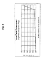
- the X-axis represents the strength of an image dot (Maximum of red, green, and blue).
- the scales of 0 - 1 represent the limits of the dynamic range (such as 0 - 255).
- the scaling function deviates from unity, the output values will be different from the input values, resulting in a change to the image.
- To scale the dynamic range from 0 to 1.0 is to simply divide a current strength (maximum of the RGB triplet) value by the maximum number that can be stored with this dynamic range. Suppose that number is 255. An arbitrary dot will have a dot maximum strength having a number between 0 and 255. To scale the dot maximum to 0 and 1.0 one divides the strength by 255.
- Both the input and the output axis represent the values of the maximum of the RGB triplet; the dot maximum.
- the input is the dot maximum under consideration.
- the output corresponds to the adjusted dot maximum for the RGB triplet that will be calculated as a result of the method.
- One method to find the maximum of an input RGB triplet is to choose one as maximum, testing each of the others, and resetting the maximum to that other if higher.
- any scaling or correction is constrained to the 1 X 1 graph shown.
- the input axis is constrained to the domain from 0 to 1 and the output axis is constrained to the range of 0 to 1. This means that the strength of an adjusted or corrected dot will not exceed the dynamic range.
- Any scaling function that can be plotted within the constrained graph can be used for virtual true color light amplification.
- the properties of a particular graph will affect the final aesthetics and application.
- a particular function is chosen as appropriate for the application; whether it be to adjust the brightness of an entire image, or a portion of the image, or other adjustment.
- Two implementations of the scaling function correction include forming a lookup table of corrections (a finite number dictated by the dynamic range); and another less efficient means is to calculate each dot independently in turn.
- a lookup table of corrections a finite number dictated by the dynamic range
- another less efficient means is to calculate each dot independently in turn.
- a given point along the graphed scaling function which provides an input and output value, is to be used to derive the correction multiplier or factor.
- a correction factor is equal to output value / input value.
- the effect of coupling these four considerations is that of Virtual True Color Light Amplification. The Dynamic Range is never exceeded and the color is always preserved.
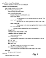
- An image can be read in various ways. Applicant has avoided the need to review the various graphical computer file formats 13 by illustrating the method on a displayed image. Applicant is aware that, currently, Visual Basic (a programming language 14 operable under the Windows operating system - all trademarks of Microsoft Corporation) and most other modem programming languages 14 have simple commands that allow for image reads.
- Visual Basic a programming language 14 operable under the Windows operating system - all trademarks of Microsoft Corporation
- pbox.Picture LoadPicture(file_in) where pbox is a 'picture box object', used for displaying pictures, Picture is a 'method' which assigns a picture to the object, LoadPicture() is the function that reads Picture Files, and file_in is the name of the file 13 that is to be read.
- the simplified code illustrates a Visual Basic implementation of the virtual true color light amplification method applied to an image.
- This simplified technique requires, at a minimum, a 16 bit video card 15 and a 24 bit card is preferable.
- the code of Fig. 2 is directed to extracting color values from the video card 15 itself. This is not the most efficient technique and could be improved significantly by storing the image in the main RAM memory 16. This would eliminate accessing the video card 15 at all and eliminate the extraction steps of stripping R, G and B values from a combined color variable such as that returned by Visual Basic function pbox.Point(icol,irow). Accessing memory 16 could result in about a 7 times efficiency gain.
- the process permits a rectangular displayed image of dots to be adjusted.
- the image may be dark, only having a maximum strength for any of the dot maximums being about 128, or half the dynamic range for the system.
- the image range is scaled to the dynamic range as a linear function. Accordingly, by normalizing the maximum of 128 to 255, the strength of all dot maximums will be doubled. Accordingly, the scaling function is merely a constant of 2 and the look up result, for any dot maximum, is 2.
- the values of the color are extracted for blue, green and red. The dot maximum is set as red and the green and blue are tested to reset the strength to the maximum amongst the three.
- the correction is looked up in the table, in this case being a constant of 2.
- Each of the values for RGB are scaled by 2, the maximum scaled value being 128 * 2 or 256 - the maximum of the dynamic range.
- the modified dot is written back to the display, all colors having been preserved and without having exceeding the dynamic range.
- Both the aperture and the shutter cause problems in and of themselves. If the subject of the photograph is moving, the shutter can only be open for a short period of time or the image will be blurred by the motion itself.
- the depth of field (which means the range of distance that is in focus) decreases. Even when focusing correctly, a wide open aperture means that only a small range of distance will be in focus. This 'distortion' is due to the spherical shape of the lens itself. When the aperture is small, the depth of field is better because only the nearly flat center of the lens was used. The smallest aperture setting provides the largest depth of field.
- photography and light gathering in general
- a motionless scene can have a large depth of field, by choosing a small aperture and a slow shutter speed.
- a racing car can only be photographed at the cost of the depth of field, the shutter cannot be open for long and so the aperture must be opened to gather more light.
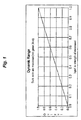
- the graph is a straight line which terminates at the point (x, 1.0) where x is the maximum of the entire measured image.
- x is the maximum of the entire measured image.
- This maximum value can be found using a modified histogram approach.
- x would be 0.25 but it could be any value between 0 and 1.
- virtual light is added in the same way that opening the aperture more would have except that it will have a depth of field associated with a superior lens. This process can also be used to make up for 'blunders' where inappropriate lens settings resulted in a too dark photograph.
- a graph can be chosen so that the darkest parts of the image will remain dark, the duller parts will brighten but also so that the bright parts of the image remain nearly unaffected.
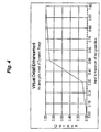
- Fig. 8, and similarly shaped smooth non-linear graphs have the effect of imitating the iris when used with the virtual true color light amplification of the present invention.
- the output image happens to more closely resemble one's visual memory of the experience. Applicant refers to this enhancement as "virtual iris".
- this non-linear graph ensures that a quality input image will result in an attractive processed image.
- the important aspects to maintain this aesthetic result is that the graph remains smooth, the slope of the graph is never zero and is also smoothly changing, and that there is a net brightening effect in total.
- the scaling function approaches the asymptote of the minimum and maximum of the system's dynamic range. The more the function approaches a tangent to the minimum and maximum of the dynamic range, the more severe the correction.
- any one frame of a photo is the result of only one aperture and shutter setting. In investigative work, this has the annoying limitation that details in certain areas of the photograph will be subtle. In a third embodiment, a process is provided for bringing out detail in that certain subtle area.
- Fig. 5 Any area of the photograph can be chosen. Having reference to Fig. 5, details in a very dark area are revealed, such as writing obscured in shadow. Fig. 6 illustrates how to bring out the details in a bright area, such as tracks in the snow. Any number of areas can have their detail enhanced by simply choosing the area of interest and applying the correction.
- any areas or portions of the image can be optimized.
- the area needs to be identified.
- this is easily done using the mouse in a 'click and drag' operation.
- This can be done in Object Oriented Programming by using the Operating System (Windows) to identify when the mouse button has been clicked.
- Windows Operating System
- subroutines for every program that are executed as soon as the mouse button is depressed or released.
- a user can select any rectangular area within the image.
- the 'coordinates' are stored in common memory as xdwn, ydwn, xup and yup. See the photographic examples #1 and #2 for the superimposed rectangle on the image.
- a histogram is simply the measurement of the number of occurrences against the value of the occurrences.
- red, green, and blue values are to be treated as a unit having a strength and ratios and not as three independent values.
- example code is provided by which to apply the modified histogram.
- the histogram is formed and its running total is known with respect to the strength of the RGB triplets of the marked area.
- the beginning and the ending significant strengths are determined, as reflected by the histogram data.
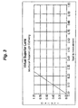
- Fig. 7b determines the range of strength index (hmin and hmax) corresponding to the range of strengths within the box selected by the user.
- the modified histogram approach found 0.30 (of the dynamic range maximum) and 0.50 (of the dynamic range maximum) to be the minimum and maximum strength values of the portion of the image selected by the user. (See photographic examples #1, #2, for the boxes).
- the output strength range of the selected area was originally set to 0.1 to 0.9 of the dynamic range maximum. It was later reset to 0.2 to 0.9 as these numbers simply seemed better after observing many images.
- the graph of Fig. 4 can be thought of, in the general sense, as having 3 line segments each with two end points.
- Both input axes are measured in terms of the dynamic range.
- the input values are in terms of the strength (max of RGB) of the dot.
- the graph never leaves the 0 to 1 'box'.
- linear equations and scaling factors are determined.
- An array of corrections or scaling factors can be formed from the three equations. Dividing the output values by the system dynamic range produces the ratio of output to input.
- This virtual detail enhancement technique or forensic flash due to its ability to delve into the normally obscured areas, maximizes the dynamic range of any target so that the details are enhanced. This is not restricted to the target area but any part of the photograph that has similar strengths to the user's choice will also be so enhanced. Any target area can be selected and so there can be many valuable corrections performed on the same photograph. Those areas which were stronger than the strength range picked by the user remain as useful references due to the 'true color' nature of the correction.
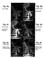
- Figs. 9 and 10 illustrate corrections to the limitations that occur from the physical light gathering devices or image recorders.
- the one aperture and shutter setting per frame means that a photograph is likely to vary from one's memory of the experience of being there.
- the eye's iris adjusts itself when experiencing contrasts. In a park on a sunny day, the iris opens up when moving from sunlight to the shade so that you remember all the grass as being green whereas photos often show shaded grass as black.
- Figs. 9b - 9d illustrate prior art image brightening techniques.
- Fig. 9b does so by increasing the image brightness by 80%. While the image of Fig. 9b is brighter, the colors are badly faded and the sky has also experienced change in color.
- Fig. 9c illustrates the prior art brightened image of Fig. 9b with contrast set to 50%. Contrast is increased in an attempt to try to restore the colors lost in brightening. Notice how much of the detail of the image is lost. The process has pushed many of the dots past the edge - outside of the dynamic range.
- Fig. 9d illustrates the brightened image of Fig. 9b with the saturation set to 50%. Increase in saturation is another technique for restoring the colors. As a result, the sky is almost returned to what it was but the rest of the image has significant and unsightly color distortions.
- Fig. 9f the image range of 5 to 254 is linearly mapped to 0 to 255. The effect is small because the original image was nearly full range already. It does, however, ensure that we have the full dynamic range in the output image.
- Fig. 9f the scaling function of Fig. 8 was applied for obtaining a superior image. All the colors are true to the image, as it was scanned, and are vibrant, just as they would have been to the eye with no loss of detail.
- the stones are in the shadows due to the extreme lighting conditions.
- the virtual iris process of the present invention compensates in a similar way that the iris does automatically, turning the poor photo into a good one.
- Fig. 10a the subject is very dark and again uses all/most of dynamic range (only 1% of the hits being outside of a strength of 6 and 253).
- This image had been "pre-processed” by others to bring out detail - notice how the sky is nearly white but clouds are still available (reproduction of the Figures in this application does not necessarily preserve the actual presence of the clouds).
- the prior art had taken it "as far” as its could but the subject was still too dark.
- Fig. 10b illustrates prior art brightening of the image by 60%. While image is brighter, the colors are badly faded and the stones have lost all their color. Some of the detail is also lost by this process alone.
- Fig. 10c is the brightened image of Fig. 10b with contrast set to 40%. Notice that the stones have, in areas, regained some color but not in other areas. Also notice how much more of the detail of the image is lost.
- Fig. 10d is the brightened image of Fig. 10b with saturation set to 15%. There is improved color that is "sort of right in a way” but it also adds artificial colors, such as some reds and yellows. Even in photos where not much correction is needed, manipulation of saturation for each dot ends up with different RGB ratios than were recorded. At best, one ends up with a compromise solution.
- Fig. 11a the satellite is in the shadows and the surface is very dark. This often happens in space because of the extreme contrast in lighting. Important 'docking' holes cannot be seen.
- a window or box was selected within the dark area and the histogram approach used to build a correction graph suited for that area.
- the tail area is selected and the histogram approach used to build a correction graph suited for that area.
- the processed image shows the lettering in the previously obscured, dark area.
- the blimp is now identified as COLUMBIA N3A.
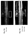
- the car's license plate is mostly shrouded in shadows.
- the car cannot be identified because the plate cannot be read.
- the plate is selected and the histogram approach used to build a correction graph suited for that area.
- the processed image shows that the car does not have a normal plate at all but, instead, the words: Classic Mustang.
- Fig. 14a there are two people skiing. Their tracks are identifiable, but subtle.
- a window or box was selected within the overexposed area of the tracks in the snow and the histogram approach used to build a correction graph suited for that area.
- Figure 14c is the result of the histogram approach used to build a correction graph uniquely suited to this area of the photo. The features of the skier are more clearly visible than in the original photo shown in Fig. 14a.
- the key concepts are here expressed as the combination of the following six factors: correcting in RGB color space, the correction graph; the definition of the correction axes; constraint of domain and range to the system's dynamic range; properties of the graph; and application of the same correction factor to each of R, G and B in the triplet.
- the correction must be applied to the RGB color space to maintain true color.
- Any correction graph can be used that embodies the above characteristics. Both the input and the output axes represent the maximum of the RGB triplet. The input is the maximum of the RGB triplet under consideration and the output corresponds to the maximum of the RGB triplet that is calculated as a result of virtual true color light amplification.
- the correction is constrained to the dynamic range. This means that the strength of the calculated dot is constrained to the dynamic range.
- Any graph that can be plotted within the constraints can be used for the process. The properties of a particular graph will affect the emphasis of the correction. Again, all three of the RGB values must be multiplied by the scaling factor derived from the graph. A given point on the graph has an input and output value. The correction equals the ratio (division) of these two and all three of the RGB triplet values are multiplied by this ratio of output to input.
Landscapes
- Engineering & Computer Science (AREA)
- Multimedia (AREA)
- Signal Processing (AREA)
- Physics & Mathematics (AREA)
- General Physics & Mathematics (AREA)
- Theoretical Computer Science (AREA)
- Image Processing (AREA)
- Facsimile Image Signal Circuits (AREA)
- Organic Low-Molecular-Weight Compounds And Preparation Thereof (AREA)
- Color Image Communication Systems (AREA)
- Processing Or Creating Images (AREA)
- Toys (AREA)
- Luminescent Compositions (AREA)
- Holo Graphy (AREA)
Applications Claiming Priority (3)
| Application Number | Priority Date | Filing Date | Title |
|---|---|---|---|
| US12904199P | 1999-04-13 | 1999-04-13 | |
| US129041P | 1999-04-13 | ||
| PCT/CA2000/000400 WO2000062528A1 (en) | 1999-04-13 | 2000-04-10 | Virtual true color light amplification |
Publications (2)
| Publication Number | Publication Date |
|---|---|
| EP1177678A1 EP1177678A1 (en) | 2002-02-06 |
| EP1177678B1 true EP1177678B1 (en) | 2003-09-17 |
Family
ID=22438204
Family Applications (1)
| Application Number | Title | Priority Date | Filing Date |
|---|---|---|---|
| EP00916733A Expired - Lifetime EP1177678B1 (en) | 1999-04-13 | 2000-04-10 | Virtual true color light amplification |
Country Status (13)
| Country | Link |
|---|---|
| EP (1) | EP1177678B1 (es) |
| JP (1) | JP4841039B2 (es) |
| KR (1) | KR20010113791A (es) |
| CN (1) | CN1179546C (es) |
| AT (1) | ATE250309T1 (es) |
| AU (1) | AU771979B2 (es) |
| CA (1) | CA2368544C (es) |
| DE (1) | DE60005332T2 (es) |
| GB (1) | GB2363933B (es) |
| HK (1) | HK1048213B (es) |
| MX (1) | MXPA01010248A (es) |
| NZ (1) | NZ514714A (es) |
| WO (1) | WO2000062528A1 (es) |
Families Citing this family (5)
| Publication number | Priority date | Publication date | Assignee | Title |
|---|---|---|---|---|
| KR101893793B1 (ko) | 2011-05-17 | 2018-10-04 | 삼성전자주식회사 | 컴퓨터 그래픽 영상의 실감도 증강을 위한 장치 및 방법 |
| ES2641371T3 (es) * | 2012-10-08 | 2017-11-08 | Koninklijke Philips N.V. | Procesamiento de imágenes con cambio de luminancia con restricciones de color |
| CN108711142B (zh) * | 2018-05-22 | 2020-09-29 | 深圳市华星光电技术有限公司 | 图像处理方法及图像处理装置 |
| CN109272459B (zh) | 2018-08-20 | 2020-12-01 | Oppo广东移动通信有限公司 | 图像处理方法、装置、存储介质及电子设备 |
| CN108900819B (zh) | 2018-08-20 | 2020-09-15 | Oppo广东移动通信有限公司 | 图像处理方法、装置、存储介质及电子设备 |
Family Cites Families (9)
| Publication number | Priority date | Publication date | Assignee | Title |
|---|---|---|---|---|
| US3684825A (en) * | 1971-02-19 | 1972-08-15 | Rca Corp | Contrast compression circuits |
| JPS59163953A (ja) * | 1983-03-08 | 1984-09-17 | Canon Inc | 画像処理装置 |
| US4736244A (en) * | 1984-12-12 | 1988-04-05 | Fuji Photo Film Co., Ltd. | Color film inspection system and data output method therefor |
| US4729016A (en) * | 1985-05-06 | 1988-03-01 | Eastman Kodak Company | Digital color image processing method and apparatus employing three color reproduction functions for adjusting both tone scale and color balance |
| US5398123A (en) * | 1988-08-31 | 1995-03-14 | Canon Kabushiki Kaisha | Image processing method and apparatus capable of automatic color masking |
| JP2748678B2 (ja) * | 1990-10-09 | 1998-05-13 | 松下電器産業株式会社 | 階調補正方法および階調補正装置 |
| EP0603908A3 (en) * | 1992-12-25 | 1996-02-07 | Dainippon Screen Mfg | Method and apparatus for converting image signals. |
| JP3335507B2 (ja) * | 1995-09-19 | 2002-10-21 | 京セラミタ株式会社 | カラー画像調整装置およびカラー画像調整方法 |
| US5818975A (en) * | 1996-10-28 | 1998-10-06 | Eastman Kodak Company | Method and apparatus for area selective exposure adjustment |
-
2000
- 2000-04-10 EP EP00916733A patent/EP1177678B1/en not_active Expired - Lifetime
- 2000-04-10 CN CNB008086907A patent/CN1179546C/zh not_active Expired - Lifetime
- 2000-04-10 CA CA002368544A patent/CA2368544C/en not_active Expired - Lifetime
- 2000-04-10 DE DE60005332T patent/DE60005332T2/de not_active Expired - Lifetime
- 2000-04-10 MX MXPA01010248A patent/MXPA01010248A/es active IP Right Grant
- 2000-04-10 AU AU38001/00A patent/AU771979B2/en not_active Expired
- 2000-04-10 JP JP2000611483A patent/JP4841039B2/ja not_active Expired - Lifetime
- 2000-04-10 NZ NZ514714A patent/NZ514714A/en unknown
- 2000-04-10 GB GB0124644A patent/GB2363933B/en not_active Expired - Lifetime
- 2000-04-10 WO PCT/CA2000/000400 patent/WO2000062528A1/en active IP Right Grant
- 2000-04-10 KR KR1020017012996A patent/KR20010113791A/ko not_active Application Discontinuation
- 2000-04-10 AT AT00916733T patent/ATE250309T1/de not_active IP Right Cessation
-
2002
- 2002-11-06 HK HK02108075.9A patent/HK1048213B/zh unknown
Also Published As
| Publication number | Publication date |
|---|---|
| KR20010113791A (ko) | 2001-12-28 |
| NZ514714A (en) | 2003-11-28 |
| DE60005332D1 (de) | 2003-10-23 |
| ATE250309T1 (de) | 2003-10-15 |
| JP4841039B2 (ja) | 2011-12-21 |
| AU3800100A (en) | 2000-11-14 |
| CN1179546C (zh) | 2004-12-08 |
| CA2368544A1 (en) | 2000-10-19 |
| WO2000062528A1 (en) | 2000-10-19 |
| MXPA01010248A (es) | 2003-07-21 |
| GB2363933A (en) | 2002-01-09 |
| CA2368544C (en) | 2006-10-03 |
| JP2002542678A (ja) | 2002-12-10 |
| DE60005332T2 (de) | 2004-06-17 |
| HK1048213B (zh) | 2005-09-16 |
| HK1048213A1 (en) | 2003-03-21 |
| CN1354950A (zh) | 2002-06-19 |
| AU771979B2 (en) | 2004-04-08 |
| EP1177678A1 (en) | 2002-02-06 |
| GB0124644D0 (en) | 2001-12-05 |
| GB2363933B (en) | 2003-08-27 |
Similar Documents
| Publication | Publication Date | Title |
|---|---|---|
| US6677959B1 (en) | Virtual true color light amplification | |
| US6961066B2 (en) | Automatic color adjustment for digital images | |
| Mann | Comparametric equations with practical applications in quantigraphic image processing | |
| US5828793A (en) | Method and apparatus for producing digital images having extended dynamic ranges | |
| JP4083587B2 (ja) | 画質向上方法及びそのための装置 | |
| Ancuti et al. | Enhancing by saliency-guided decolorization | |
| CN110062160A (zh) | 图像处理方法和装置 | |
| JP2001126075A (ja) | 画像処理方法および装置並びに記録媒体 | |
| US20110013848A1 (en) | Image processing apparatus and method for controlling the same | |
| GB2549696A (en) | Image processing method and apparatus, integrated circuitry and recording medium | |
| CN100411445C (zh) | 校正图像亮度分布的图像处理方法及装置 | |
| US20170154437A1 (en) | Image processing apparatus for performing smoothing on human face area | |
| Yu et al. | Adaptive inverse hyperbolic tangent algorithm for dynamic contrast adjustment in displaying scenes | |
| Bhukhanwala et al. | Automated global enhancement of digitized photographs | |
| EP1177678B1 (en) | Virtual true color light amplification | |
| Raigonda et al. | Haze Removal Of Underwater Images Using Fusion Technique | |
| JP2006186983A (ja) | カラー画像の露出補正方法 | |
| JP4445026B2 (ja) | 画像処理方法および装置並びにプログラム | |
| JP5050141B2 (ja) | カラー画像の露出評価方法 | |
| Kumar et al. | Image Enhancement Using Laplacian Gaussian Pyramid Based Fusion and Band Rationing Algorithm | |
| JP3817371B2 (ja) | 画像処理方法、装置および記録媒体 | |
| Hussin et al. | Nonlinear local-pixel-shifting color constancy algorithm | |
| Lakshmi et al. | Analysis of tone mapping operators on high dynamic range images | |
| Yung-Yao et al. | Photographic Reproduction and Enhancement Using HVS-Based Modified Histogram Equalization | |
| Lee | HDR image synthesis using visual brightness mapping and local surround-based image fusion |
Legal Events
| Date | Code | Title | Description |
|---|---|---|---|
| PUAI | Public reference made under article 153(3) epc to a published international application that has entered the european phase |
Free format text: ORIGINAL CODE: 0009012 |
|
| 17P | Request for examination filed |
Effective date: 20011015 |
|
| AK | Designated contracting states |
Kind code of ref document: A1 Designated state(s): AT BE CH CY DE DK ES FI FR GB GR IE IT LI LU MC NL PT SE |
|
| 17Q | First examination report despatched |
Effective date: 20020222 |
|
| GRAH | Despatch of communication of intention to grant a patent |
Free format text: ORIGINAL CODE: EPIDOS IGRA |
|
| RAP1 | Party data changed (applicant data changed or rights of an application transferred) |
Owner name: ATHENTECH TECHNOLOGIES INC |
|
| GRAS | Grant fee paid |
Free format text: ORIGINAL CODE: EPIDOSNIGR3 |
|
| GRAA | (expected) grant |
Free format text: ORIGINAL CODE: 0009210 |
|
| AK | Designated contracting states |
Kind code of ref document: B1 Designated state(s): AT BE CH CY DE DK ES FI FR GR IE IT LI LU MC NL PT SE |
|
| PG25 | Lapsed in a contracting state [announced via postgrant information from national office to epo] |
Ref country code: BE Free format text: LAPSE BECAUSE OF FAILURE TO SUBMIT A TRANSLATION OF THE DESCRIPTION OR TO PAY THE FEE WITHIN THE PRESCRIBED TIME-LIMIT Effective date: 20030917 Ref country code: FI Free format text: LAPSE BECAUSE OF FAILURE TO SUBMIT A TRANSLATION OF THE DESCRIPTION OR TO PAY THE FEE WITHIN THE PRESCRIBED TIME-LIMIT Effective date: 20030917 Ref country code: CY Free format text: LAPSE BECAUSE OF FAILURE TO SUBMIT A TRANSLATION OF THE DESCRIPTION OR TO PAY THE FEE WITHIN THE PRESCRIBED TIME-LIMIT Effective date: 20030917 Ref country code: NL Free format text: LAPSE BECAUSE OF FAILURE TO SUBMIT A TRANSLATION OF THE DESCRIPTION OR TO PAY THE FEE WITHIN THE PRESCRIBED TIME-LIMIT Effective date: 20030917 Ref country code: AT Free format text: LAPSE BECAUSE OF FAILURE TO SUBMIT A TRANSLATION OF THE DESCRIPTION OR TO PAY THE FEE WITHIN THE PRESCRIBED TIME-LIMIT Effective date: 20030917 Ref country code: ES Free format text: LAPSE BECAUSE OF FAILURE TO SUBMIT A TRANSLATION OF THE DESCRIPTION OR TO PAY THE FEE WITHIN THE PRESCRIBED TIME-LIMIT Effective date: 20030917 |
|
| REG | Reference to a national code |
Ref country code: CH Ref legal event code: EP |
|
| REF | Corresponds to: |
Ref document number: 60005332 Country of ref document: DE Date of ref document: 20031023 Kind code of ref document: P |
|
| REG | Reference to a national code |
Ref country code: IE Ref legal event code: FG4D |
|
| PG25 | Lapsed in a contracting state [announced via postgrant information from national office to epo] |
Ref country code: GR Free format text: LAPSE BECAUSE OF FAILURE TO SUBMIT A TRANSLATION OF THE DESCRIPTION OR TO PAY THE FEE WITHIN THE PRESCRIBED TIME-LIMIT Effective date: 20031217 Ref country code: DK Free format text: LAPSE BECAUSE OF FAILURE TO SUBMIT A TRANSLATION OF THE DESCRIPTION OR TO PAY THE FEE WITHIN THE PRESCRIBED TIME-LIMIT Effective date: 20031217 Ref country code: SE Free format text: LAPSE BECAUSE OF FAILURE TO SUBMIT A TRANSLATION OF THE DESCRIPTION OR TO PAY THE FEE WITHIN THE PRESCRIBED TIME-LIMIT Effective date: 20031217 |
|
| PG25 | Lapsed in a contracting state [announced via postgrant information from national office to epo] |
Ref country code: PT Free format text: LAPSE BECAUSE OF FAILURE TO SUBMIT A TRANSLATION OF THE DESCRIPTION OR TO PAY THE FEE WITHIN THE PRESCRIBED TIME-LIMIT Effective date: 20031226 |
|
| REG | Reference to a national code |
Ref country code: CH Ref legal event code: NV Representative=s name: ISLER & PEDRAZZINI AG |
|
| NLV1 | Nl: lapsed or annulled due to failure to fulfill the requirements of art. 29p and 29m of the patents act | ||
| PG25 | Lapsed in a contracting state [announced via postgrant information from national office to epo] |
Ref country code: LU Free format text: LAPSE BECAUSE OF NON-PAYMENT OF DUE FEES Effective date: 20040410 |
|
| PG25 | Lapsed in a contracting state [announced via postgrant information from national office to epo] |
Ref country code: IE Free format text: LAPSE BECAUSE OF NON-PAYMENT OF DUE FEES Effective date: 20040412 |
|
| PG25 | Lapsed in a contracting state [announced via postgrant information from national office to epo] |
Ref country code: MC Free format text: LAPSE BECAUSE OF NON-PAYMENT OF DUE FEES Effective date: 20040430 |
|
| ET | Fr: translation filed | ||
| PLBE | No opposition filed within time limit |
Free format text: ORIGINAL CODE: 0009261 |
|
| STAA | Information on the status of an ep patent application or granted ep patent |
Free format text: STATUS: NO OPPOSITION FILED WITHIN TIME LIMIT |
|
| 26N | No opposition filed |
Effective date: 20040618 |
|
| REG | Reference to a national code |
Ref country code: IE Ref legal event code: MM4A |
|
| PG25 | Lapsed in a contracting state [announced via postgrant information from national office to epo] |
Ref country code: IT Free format text: LAPSE BECAUSE OF NON-PAYMENT OF DUE FEES Effective date: 20050410 |
|
| REG | Reference to a national code |
Ref country code: CH Ref legal event code: PCAR Free format text: ISLER & PEDRAZZINI AG;POSTFACH 1772;8027 ZUERICH (CH) |
|
| PGRI | Patent reinstated in contracting state [announced from national office to epo] |
Ref country code: IT Effective date: 20090401 |
|
| PGFP | Annual fee paid to national office [announced via postgrant information from national office to epo] |
Ref country code: IT Payment date: 20100427 Year of fee payment: 11 |
|
| PG25 | Lapsed in a contracting state [announced via postgrant information from national office to epo] |
Ref country code: IT Free format text: LAPSE BECAUSE OF NON-PAYMENT OF DUE FEES Effective date: 20110410 |
|
| REG | Reference to a national code |
Ref country code: FR Ref legal event code: PLFP Year of fee payment: 17 |
|
| REG | Reference to a national code |
Ref country code: FR Ref legal event code: PLFP Year of fee payment: 18 |
|
| REG | Reference to a national code |
Ref country code: FR Ref legal event code: PLFP Year of fee payment: 19 |
|
| PGFP | Annual fee paid to national office [announced via postgrant information from national office to epo] |
Ref country code: DE Payment date: 20190418 Year of fee payment: 20 |
|
| PGFP | Annual fee paid to national office [announced via postgrant information from national office to epo] |
Ref country code: FR Payment date: 20190424 Year of fee payment: 20 |
|
| PGFP | Annual fee paid to national office [announced via postgrant information from national office to epo] |
Ref country code: CH Payment date: 20190418 Year of fee payment: 20 |
|
| REG | Reference to a national code |
Ref country code: DE Ref legal event code: R071 Ref document number: 60005332 Country of ref document: DE |
|
| REG | Reference to a national code |
Ref country code: CH Ref legal event code: PL |