EP1177458B1 - Laser photoelectric sensor - Google Patents
Laser photoelectric sensor Download PDFInfo
- Publication number
- EP1177458B1 EP1177458B1 EP00926504A EP00926504A EP1177458B1 EP 1177458 B1 EP1177458 B1 EP 1177458B1 EP 00926504 A EP00926504 A EP 00926504A EP 00926504 A EP00926504 A EP 00926504A EP 1177458 B1 EP1177458 B1 EP 1177458B1
- Authority
- EP
- European Patent Office
- Prior art keywords
- laser
- laser light
- light
- further characterized
- set forth
- Prior art date
- Legal status (The legal status is an assumption and is not a legal conclusion. Google has not performed a legal analysis and makes no representation as to the accuracy of the status listed.)
- Expired - Lifetime
Links
- 230000003287 optical effect Effects 0.000 claims description 12
- 238000000034 method Methods 0.000 claims description 9
- 230000001360 synchronised effect Effects 0.000 claims description 5
- 238000001514 detection method Methods 0.000 claims description 4
- 238000002329 infrared spectrum Methods 0.000 claims 1
- 230000008901 benefit Effects 0.000 description 3
- 230000001105 regulatory effect Effects 0.000 description 3
- 230000003750 conditioning effect Effects 0.000 description 2
- 238000005259 measurement Methods 0.000 description 2
- 230000004048 modification Effects 0.000 description 2
- 238000012986 modification Methods 0.000 description 2
- OAICVXFJPJFONN-UHFFFAOYSA-N Phosphorus Chemical compound [P] OAICVXFJPJFONN-UHFFFAOYSA-N 0.000 description 1
- 239000004793 Polystyrene Substances 0.000 description 1
- NIXOWILDQLNWCW-UHFFFAOYSA-N acrylic acid group Chemical group C(C=C)(=O)O NIXOWILDQLNWCW-UHFFFAOYSA-N 0.000 description 1
- 230000003321 amplification Effects 0.000 description 1
- 230000015556 catabolic process Effects 0.000 description 1
- 230000008859 change Effects 0.000 description 1
- 238000006731 degradation reaction Methods 0.000 description 1
- 230000001066 destructive effect Effects 0.000 description 1
- 238000010586 diagram Methods 0.000 description 1
- 239000011521 glass Substances 0.000 description 1
- 239000000463 material Substances 0.000 description 1
- 230000003278 mimic effect Effects 0.000 description 1
- 238000012544 monitoring process Methods 0.000 description 1
- 238000003199 nucleic acid amplification method Methods 0.000 description 1
- 230000002093 peripheral effect Effects 0.000 description 1
- 239000004417 polycarbonate Substances 0.000 description 1
- 229920000515 polycarbonate Polymers 0.000 description 1
- 229920002223 polystyrene Polymers 0.000 description 1
- 230000036632 reaction speed Effects 0.000 description 1
- 230000004044 response Effects 0.000 description 1
- 230000035945 sensitivity Effects 0.000 description 1
- 230000000007 visual effect Effects 0.000 description 1
Images

Classifications
-
- G—PHYSICS
- G01—MEASURING; TESTING
- G01S—RADIO DIRECTION-FINDING; RADIO NAVIGATION; DETERMINING DISTANCE OR VELOCITY BY USE OF RADIO WAVES; LOCATING OR PRESENCE-DETECTING BY USE OF THE REFLECTION OR RERADIATION OF RADIO WAVES; ANALOGOUS ARRANGEMENTS USING OTHER WAVES
- G01S7/00—Details of systems according to groups G01S13/00, G01S15/00, G01S17/00
- G01S7/48—Details of systems according to groups G01S13/00, G01S15/00, G01S17/00 of systems according to group G01S17/00
- G01S7/497—Means for monitoring or calibrating
-
- G—PHYSICS
- G01—MEASURING; TESTING
- G01J—MEASUREMENT OF INTENSITY, VELOCITY, SPECTRAL CONTENT, POLARISATION, PHASE OR PULSE CHARACTERISTICS OF INFRARED, VISIBLE OR ULTRAVIOLET LIGHT; COLORIMETRY; RADIATION PYROMETRY
- G01J1/00—Photometry, e.g. photographic exposure meter
- G01J1/42—Photometry, e.g. photographic exposure meter using electric radiation detectors
-
- G—PHYSICS
- G01—MEASURING; TESTING
- G01S—RADIO DIRECTION-FINDING; RADIO NAVIGATION; DETERMINING DISTANCE OR VELOCITY BY USE OF RADIO WAVES; LOCATING OR PRESENCE-DETECTING BY USE OF THE REFLECTION OR RERADIATION OF RADIO WAVES; ANALOGOUS ARRANGEMENTS USING OTHER WAVES
- G01S17/00—Systems using the reflection or reradiation of electromagnetic waves other than radio waves, e.g. lidar systems
- G01S17/02—Systems using the reflection of electromagnetic waves other than radio waves
- G01S17/04—Systems determining the presence of a target
-
- G—PHYSICS
- G01—MEASURING; TESTING
- G01S—RADIO DIRECTION-FINDING; RADIO NAVIGATION; DETERMINING DISTANCE OR VELOCITY BY USE OF RADIO WAVES; LOCATING OR PRESENCE-DETECTING BY USE OF THE REFLECTION OR RERADIATION OF RADIO WAVES; ANALOGOUS ARRANGEMENTS USING OTHER WAVES
- G01S7/00—Details of systems according to groups G01S13/00, G01S15/00, G01S17/00
- G01S7/48—Details of systems according to groups G01S13/00, G01S15/00, G01S17/00 of systems according to group G01S17/00
- G01S7/481—Constructional features, e.g. arrangements of optical elements
- G01S7/4811—Constructional features, e.g. arrangements of optical elements common to transmitter and receiver
-
- G—PHYSICS
- G01—MEASURING; TESTING
- G01S—RADIO DIRECTION-FINDING; RADIO NAVIGATION; DETERMINING DISTANCE OR VELOCITY BY USE OF RADIO WAVES; LOCATING OR PRESENCE-DETECTING BY USE OF THE REFLECTION OR RERADIATION OF RADIO WAVES; ANALOGOUS ARRANGEMENTS USING OTHER WAVES
- G01S7/00—Details of systems according to groups G01S13/00, G01S15/00, G01S17/00
- G01S7/48—Details of systems according to groups G01S13/00, G01S15/00, G01S17/00 of systems according to group G01S17/00
- G01S7/483—Details of pulse systems
- G01S7/484—Transmitters
-
- G—PHYSICS
- G01—MEASURING; TESTING
- G01J—MEASUREMENT OF INTENSITY, VELOCITY, SPECTRAL CONTENT, POLARISATION, PHASE OR PULSE CHARACTERISTICS OF INFRARED, VISIBLE OR ULTRAVIOLET LIGHT; COLORIMETRY; RADIATION PYROMETRY
- G01J1/00—Photometry, e.g. photographic exposure meter
- G01J1/42—Photometry, e.g. photographic exposure meter using electric radiation detectors
- G01J1/44—Electric circuits
- G01J2001/4446—Type of detector
Definitions
- the present invention relates to the laser sensor art.
- laser sensors have included a laser diode or other laser source which was focused to a preselected focal length by a convergent focusing lens.
- Laser light reflected from a reflector was received by another convergent lens with a relatively long focal length and focused on a photodiode detector.
- the output of the photodiode was monitored and an electronic signal was generated indicative of the reception of the reflected laser beam or the absence of the reflected laser beam.
- some laser sensors included a feedback system, such as a continuous wave type feedback system, between the laser source and the detector.
- the prior laser sensors are typically operative for a relatively short distance range, on the order of up to 30 meters. Even within that distance range, different lenses on the laser are required for different distances.
- the selected laser sensor must be matched to the application.
- the receiving lenses again must be compatible with the distance for which the sensor is calibrated. The longer focal length lenses at the receiving side tend to use only part of the photodetector as the length becomes longer, reducing sensitivity. If the length is too long, the lens may focus off the photodetector.
- U.S. Patent No. 3,941,483 to Ferrin discloses a target identification apparatus. Laser energy from objects over a wide, about 60°, field of view is focused by a Fresnel lens on a detector. A projector projects a display on a pilot's visor which corresponds to the source of the laser energy.
- U.S. Patent No. 3,614,449 of Ward describes an optical tracking system for outer space use.
- the Ward system uses a split lens for both the acquisition and tracking functions.
- Peripheral equipment rotates the system to track a targeted object.
- the present invention provides a new and improved laser sensor which overcomes the above-referenced problems and others.
- a laser sensor includes a laser diode.
- a laser drive circuit provides power to the laser diode to cause it to emit light.
- a photoreceiver receives reflected laser light.
- An optical lens disposed adjacent the photoreceiver focuses reflected laser light into the photoreceiver. The optical lens as an f-number less than 1.0.
- a collimating lens mounted adjacent the laser diode collimates the emitted laser light.
- the photoreceiver includes a synchronous detector. The photoreceiver generates enable signals for intermittently enabling driving of the laser diode and comparing whether the received light temporally corresponds to periods in which the laser diode was enabled. An output signal indicative of the receipt or non-receipt of reflected laser light is produced.
- a method of laser sensing is provided.
- Laser light is emitted and transmitted across a region of interest.
- the laser light is reflected back across the region of interest again and focused with a lens having an f-number less than 1.0.
- the focused laser light is detected.
- the emitted laser light is collimated into a beam of parallel rays.
- the generation of laser light and the detection of received laser light are synchronously controlled to distinguish between received laser light and received stray light. A presence/absence of detected, reflected laser light is determined.
- the optical lens is a ball lens.
- One advantage of the present invention is that it senses over ranges of up to 50-70 meters.
- Another advantage of the present invention is that no lens replacements are required to change between long and short distance ranges.
- the same sensor can be used for either long or short distances without lens changes.
- the invention may take form in various components and arrangements of components, and in various steps and arrangements of steps.
- the drawings are only for purposes of illustrating a preferred embodiment and are not to be construed as limiting the invention.
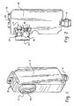
- the laser sensor includes a housing 10 including a forward projecting portion 12 .
- the forward projecting portion includes a window 14 through which a laser beam is projected and through which reflected laser light is received.
- An electrical fitting or connector 16 includes contacts for electrical power in and signals indicative of whether or not the laser beam is interrupted going out. Red and green LEDs 18 provide a local, visual indication regarding whether the beam is interrupted and whether the laser sensor is powered.
- a circuit board 20 is connected with the electrical connector 16 and supported centrally in the housing 10 .
- the circuit board also supports a laser diode 22 , visible red in the preferred embodiment.
- a collimating lens 24 is mechanically mounted adjacent the laser diode 22 .
- the collimating lens collimates the light, rather than focusing it on a focal point at a selected distance.
- the collimating lens causes a laser beam of parallel rays to be emitted without converging.
- the collimated parallel rays are more forgiving of object size and target distance relative to focused beams.
- the reflected laser light returning through the window 14 encounters a ball lens 26 which focuses the light onto an active surface of a photoreceiver 28 .
- the ball lens has a larger field of view which adds flexibility in target size and target distance.
- the ball lens has a very short focal length, on the order of its radius, 3 mm in the preferred embodiment, for focusing parallel and other rays on the photoactive surface. Ball lens with diameters of 3-12 mm are also contemplated.
- the ball lens has a high efficiency due to its low f-number (focal length ⁇ aperture).
- the index of refraction of the ball lens is selected relative to the wavelength of the selected light such that the light is focused substantially on the circumference of the sphere which abuts the photosensitive surface, preferably an index of 1.5 ⁇ 0.1 at 650 nm.
- the ball lens can also be tinted to function concurrently as a filter.
- Other receiving lenses 26 are also contemplated.
- Other lenses with an f-number of less than 1.0 can also produce satisfactory results, with an f-number of 0.6-0.7 being optimal.
- Optical lasers in the near infrared range preferably below 1100 nanometers are also contemplated.
- the use of lasers with significantly higher or lower wavelengths is also contemplated, provided a sensor which is sensitive to that wavelength is selected.
- a phosphor which is energized by one wavelength and which emits light of another wavelength may be used as an interface between mismatched lasers and detectors.
- a DC voltage contact and a ground contact pair 30 are physically located in the electrical connector 16 .
- the contact 30 preferably receives 10-30 volts DC.
- a power conditioning circuit 32 including a voltage regulator chip 34 converts the received power into a regulated 6 volts.
- the regulated voltage powers a sensing circuit 40 and a laser drive circuit 42 .
- the sensing circuit includes a photosensor. More specifically, the sensing circuit includes a pulse modulation synchronous detector chip, such as a Sharp IS450.
- the synchronous detector chip includes the light sensitive circuit, accompanying amplification and signal conditioning circuitry, and the like. In the preferred embodiment, the same chip also includes the synchronization circuitry, although such circuitry could be provided separately. That is, the chip 28 further generates pulses for pulsing the laser diode 22 and an internal comparitor for comparing whether received light is received at an appropriate timing relative to the pulsing of the laser diode.
- the travel time of the light from the laser diode to the reflective surface and back to the photosensitive surface, and the speed of the circuitry within the detector chip 28 there is a known time interval or window within which reflected laser light is received.
- the comparitor filters out any light received at other times.
- the pulse modulation output of the detector chip 28 is connected to a gated feedback circuit 46 for turning the laser diode ON and OFF.
- a reference voltage source 48 provides the laser diode assembly with a regulated reference voltage that is proportional to the amount of emitted light to provide an automatic, dynamic intensity adjustment.
- the reference voltage source is connected to a photodiode 50 mounted behind the laser diode 22 for sensing its output.
- the gated feedback circuit includes switches 52, 54 for switching the reference voltage from source 48 in and out for sharper pulses, particularly for faster rise times and less phase delay without excessive over-shoot of the laser drive current. The faster rise time and less phase delay allows the circuit to function with the synchronous detection circuitry with little degradation and performance while limiting destructive leading edge current peaks caused by the inherent lag in the response of the feedback monitoring photodiode 54 .
- An intensity adjustment device 56 is used to adjust the intensity of the laser diode. For measurements over a range of 50-70 meters, the intensity adjustment causes the laser diode 22 to be driven substantially at its highest brightness. However, for measurements made over shorter distances, the intensity of the diode is dimmed. When the diode intensity is too high, the target can mimic the reflector. An object passing through the beam close to the housing 20 can reflect a magnitude of laser light back to the photoreceiver 28 that is within the same magnitude range as light returned from the reflector. The collimated parallel rays accurately target a reflector at distances of 1 meter or less up to 70 meters or more, with no lens modification. The ball lens with its wide field of view can receive light reflected from targets as close as 1 meter or less up to 70 meters or more, with no lens modification. Thus, the intensity adjustment is the adjustment for the distance between the laser and the reflector.
- the detection circuit 28 When the detection circuit 28 detects reflected laser light, it outputs a signal to a dark-on/light-on selection circuit 60 . That is, depending on the application, it may be advantageous to have an output signal when reflected light is received or it may be advantageous to have an output signal whenever no reflected light is received.
- the dark-on/light-on circuit includes a switch 62 with which the user can make this selection.
- An output circuit 64 shapes the output signal to control a pair of analogous output transistors to produce a PNP output on a PNP output terminal 66 and an NPN output on an NPN output terminal 68 .
- the output terminals 66 , 68 which are again located in the electrical connector 16 , carry the high and low signals from the transistors to downstream equipment.
Landscapes
- Engineering & Computer Science (AREA)
- Physics & Mathematics (AREA)
- General Physics & Mathematics (AREA)
- Computer Networks & Wireless Communication (AREA)
- Radar, Positioning & Navigation (AREA)
- Remote Sensing (AREA)
- Electromagnetism (AREA)
- Spectroscopy & Molecular Physics (AREA)
- Optical Radar Systems And Details Thereof (AREA)
Description
Claims (14)
- A laser sensor including a laser diode, a laser drive circuit for providing power to the laser diode to cause it to emit laser light, a photoreceiver for receiving reflected laser light, and an optical lens disposed adjacent the photoreceiver for focusing the reflected laser light onto the photoreceiver, the optical lens having an f-number less than 1.0, the laser sensor characterized by:a collimating lens mounted adjacent the laser diode for collimating the emitted laser light;the photoreceiver including a synchronous detector, the photoreceiver generating enable signals for intermittently enabling driving the laser diode and comparing whether received light temporally corresponds to periods in which the laser diode was enabled; and,the photoreceiver producing an output signal indicative of receipt/non-receipt of reflected laser light.
- The laser sensor as set forth in claim 1 further characterized by:the optical lens having an f-number of 0.6-0.7.
- The laser sensor as set forth in claim 2 further characterized by:the optical lens being a ball lens.
- The laser sensor as set forth in any one of preceding claims 1, 2, and 3, further characterized by:a reference voltage source which carries a reference voltage which varies in accordance with an amount of light emitted by the laser diode; anda gated feedback circuit controlled by the output signal of the photoreceiver for gating the reference voltage to the laser driving circuit.
- The laser sensor as set forth in claim 4 further characterized by:the gated feedback circuit including transistors for switching the reference voltage in and out to reduce rise times in laser diode driving pulses of the laser drive circuit.
- The laser sensor as set forth in any one of preceding claims 1-5 further characterized by:an intensity adjustment for adjusting an intensity of the laser diode.
- The laser sensor as set forth in any one of preceding claims 1-6 further characterized by:the laser diode emitting light in a visible red - near infrared spectrum range and the optical lens having an index of refraction of 1.4-1.6 at 650 nm.
- A method of laser sensing including emitting laser light, transmitting the collimated beam across a region of interest, reflecting the collimated laser beam back across the region of interest, focusing the reflected laser light with a lens having a f-number less than 1.0, detecting the focused reflected laser light, the method further characterized by:collimating the laser light into a collimated beam of parallel rays;synchronously controlling intermittent generation of the laser light and detection of the received laser light to distinguish between received laser light and received stray light;determining a presence/absence of detected, reflected laser light.
- The method as set forth in claim 8 further characterized by:the f-number being between 0.6-0.7.
- The method as set forth in either one of claims 8 and 9, further characterized by:focusing the reflected laser light with a ball lens.
- The method as set forth in any one of preceding claims 8, 9, and 10, further characterized by:the collimated laser beam being transmitted at. least 40 meters before being reflected.
- The method as set forth in any one of preceding claims 8, 9, and 10 further characterized by:the collimated laser beam being transmitted over 50 meters before being reflected and being transmitted 50 meters after reflection before being focused and detected.
- The method as set forth in any one of preceding claims 8-12 further characterized by:adjusting an intensity of the generated laser light in accordance with a distance over which the laser beam is transmitted and reflected.
- The method as set forth in any one of preceding claims 8-13 further characterized by:creating a reference voltage proportional to an intensity of generated laser light and gating the reference voltage to control generation of laser light.
Applications Claiming Priority (3)
| Application Number | Priority Date | Filing Date | Title |
|---|---|---|---|
| US307110 | 1989-02-06 | ||
| US09/307,110 US6225621B1 (en) | 1999-05-07 | 1999-05-07 | Laser photoelectric sensor |
| PCT/US2000/011937 WO2000068708A1 (en) | 1999-05-07 | 2000-05-03 | Laser photoelectric sensor |
Publications (2)
| Publication Number | Publication Date |
|---|---|
| EP1177458A1 EP1177458A1 (en) | 2002-02-06 |
| EP1177458B1 true EP1177458B1 (en) | 2002-08-28 |
Family
ID=23188285
Family Applications (1)
| Application Number | Title | Priority Date | Filing Date |
|---|---|---|---|
| EP00926504A Expired - Lifetime EP1177458B1 (en) | 1999-05-07 | 2000-05-03 | Laser photoelectric sensor |
Country Status (6)
| Country | Link |
|---|---|
| US (1) | US6225621B1 (en) |
| EP (1) | EP1177458B1 (en) |
| JP (1) | JP2002544492A (en) |
| KR (1) | KR20010113911A (en) |
| DE (1) | DE60000373T2 (en) |
| WO (1) | WO2000068708A1 (en) |
Families Citing this family (17)
| Publication number | Priority date | Publication date | Assignee | Title |
|---|---|---|---|---|
| JP4930742B2 (en) * | 2001-03-29 | 2012-05-16 | 株式会社トプコン | Position detection device |
| US7063747B2 (en) * | 2002-05-29 | 2006-06-20 | Acushnet Company | Coating control system for use on a spherical object |
| RU2205426C1 (en) * | 2002-07-26 | 2003-05-27 | Атнашев Виталий Борисович | Way to view objects with use of laser brightening and facility for its implementation |
| RU2207591C1 (en) * | 2002-09-06 | 2003-06-27 | Атнашев Виталий Борисович | Method of object viewing with use of laser illumination and facility for its implementation ( variants ) |
| WO2004011959A1 (en) * | 2002-07-26 | 2004-02-05 | Vitaliy Atnashev | Method for object viewing with the aid of laser illumination and device for carrying out said method (variants) |
| JP2005233776A (en) * | 2004-02-19 | 2005-09-02 | Denso Corp | Distance detecting device and manufacturing method thereof |
| US9019632B2 (en) | 2008-05-30 | 2015-04-28 | The Invention Science Fund I Llc | Negatively-refractive focusing and sensing apparatus, methods, and systems |
| RU2478984C2 (en) * | 2011-03-24 | 2013-04-10 | Виталий Борисович Шепеленко | Method of determining distance between bodies |
| JP1518122S (en) * | 2014-06-30 | 2015-02-23 | ||
| DE102015224715A1 (en) * | 2015-12-09 | 2017-06-14 | Robert Bosch Gmbh | Sensor element, sensor device and method |
| DE102016112557B4 (en) * | 2016-07-08 | 2019-08-22 | Jenoptik Advanced Systems Gmbh | Optical steel forming unit and distance measuring device |
| CN106695133B (en) * | 2016-12-28 | 2018-05-25 | 京磁新材料有限公司 | The laser cutting method of neodymium iron boron magnetic body |
| US11493601B2 (en) * | 2017-12-22 | 2022-11-08 | Innovusion, Inc. | High density LIDAR scanning |
| US11510297B2 (en) * | 2018-12-24 | 2022-11-22 | Beijing Voyager Technology Co., Ltd. | Adaptive power control for pulsed laser diodes |
| US10826269B2 (en) | 2018-12-24 | 2020-11-03 | Beijing Voyager Technology Co., Ltd. | Multi-pulse generation for pulsed laser diodes using low-side drivers |
| DE102019127667A1 (en) * | 2019-10-15 | 2021-04-15 | Sick Ag | Distance measuring optoelectronic sensor and method for detecting a target object |
| CN114964324B (en) * | 2022-06-02 | 2025-11-07 | 中山市科维光电技术有限公司 | Control method for multifunctional photoelectric sensor by combining key and screw |
Family Cites Families (6)
| Publication number | Priority date | Publication date | Assignee | Title |
|---|---|---|---|---|
| US3614449A (en) | 1969-02-12 | 1971-10-19 | Itt | Optical tracking system utilizing a coaxial lens system |
| US3941483A (en) | 1974-04-08 | 1976-03-02 | Honeywell Inc. | Target identification apparatus |
| US4290043A (en) | 1979-10-16 | 1981-09-15 | Kaplan Irwin M | Method of and system for detecting marine obstacles |
| US4807166A (en) * | 1986-09-19 | 1989-02-21 | Summagraphics Corporation | Method and apparatus for calibrating an electro-optical mouse |
| US5289252A (en) | 1992-12-08 | 1994-02-22 | Hughes Aircraft Company | Linear frequency modulation control for FM laser radar |
| EP0709798A1 (en) | 1994-09-21 | 1996-05-01 | Opticon Sensors Europe B.V. | Wand scanner with a sensor supported by a hole in illuminating optics |
-
1999
- 1999-05-07 US US09/307,110 patent/US6225621B1/en not_active Expired - Fee Related
-
2000
- 2000-05-03 KR KR1020017014093A patent/KR20010113911A/en not_active Withdrawn
- 2000-05-03 EP EP00926504A patent/EP1177458B1/en not_active Expired - Lifetime
- 2000-05-03 JP JP2000616441A patent/JP2002544492A/en not_active Withdrawn
- 2000-05-03 DE DE60000373T patent/DE60000373T2/en not_active Expired - Fee Related
- 2000-05-03 WO PCT/US2000/011937 patent/WO2000068708A1/en not_active Ceased
Also Published As
| Publication number | Publication date |
|---|---|
| DE60000373T2 (en) | 2003-04-17 |
| US6225621B1 (en) | 2001-05-01 |
| EP1177458A1 (en) | 2002-02-06 |
| JP2002544492A (en) | 2002-12-24 |
| DE60000373D1 (en) | 2002-10-02 |
| WO2000068708A1 (en) | 2000-11-16 |
| KR20010113911A (en) | 2001-12-28 |
Similar Documents
| Publication | Publication Date | Title |
|---|---|---|
| US6611318B2 (en) | Adjustable mirror for collimated beam laser sensor | |
| EP1177458B1 (en) | Laser photoelectric sensor | |
| US5245177A (en) | Electro-optical system for detecting the presence of an object within a predetermined detection system | |
| US6897465B2 (en) | System and method for determining a distance of an object using emitted light pulses | |
| JP2648553B2 (en) | Input device | |
| EP2230537B1 (en) | Photoelectric sensor for sensing a target | |
| CN109901184A (en) | Time-of-flight component, terminal and control method of time-of-flight component | |
| JP5583120B2 (en) | Photoelectric switch and method for detecting objects | |
| EP0137966A3 (en) | Optical device for detecting coded symbols | |
| CN112292850B (en) | Projector controller and projection control method | |
| GB2326760A (en) | Optical emission device | |
| US4314239A (en) | Portable electronic alarm device | |
| US4611917A (en) | Optical system for determining an object's position | |
| CA2062550A1 (en) | Optical distance measuring apparatus | |
| CN209417320U (en) | A kind of photoelectric sensor for object to be detected with holes | |
| CN115097416B (en) | Laser receiving module and laser radar | |
| CN221977116U (en) | Uniform illumination depth camera and electronic device | |
| Lataire | Optical Sensors For Factory Automation. | |
| JPS60235027A (en) | Narrow wavelength band emitter/receiver | |
| RU2140622C1 (en) | Gear measuring distances | |
| JP3532986B2 (en) | Lightwave ranging device | |
| GB2200810A (en) | Optical proximity detector | |
| KR20260009551A (en) | Frequency modulated continuous wave lidar and autonomous vehicle driving method using thereof | |
| JPS60235028A (en) | Narrow wavelength band light emitting and receiving apparatus | |
| RU2230346C1 (en) | Facility for remote detection of optical light-returning systems |
Legal Events
| Date | Code | Title | Description |
|---|---|---|---|
| PUAI | Public reference made under article 153(3) epc to a published international application that has entered the european phase |
Free format text: ORIGINAL CODE: 0009012 |
|
| GRAG | Despatch of communication of intention to grant |
Free format text: ORIGINAL CODE: EPIDOS AGRA |
|
| 17P | Request for examination filed |
Effective date: 20011024 |
|
| AK | Designated contracting states |
Kind code of ref document: A1 Designated state(s): AT BE CH CY DE DK ES FI FR GB GR IE IT LI LU MC NL PT SE |
|
| 17Q | First examination report despatched |
Effective date: 20020208 |
|
| GRAG | Despatch of communication of intention to grant |
Free format text: ORIGINAL CODE: EPIDOS AGRA |
|
| GRAH | Despatch of communication of intention to grant a patent |
Free format text: ORIGINAL CODE: EPIDOS IGRA |
|
| GRAH | Despatch of communication of intention to grant a patent |
Free format text: ORIGINAL CODE: EPIDOS IGRA |
|
| GRAA | (expected) grant |
Free format text: ORIGINAL CODE: 0009210 |
|
| AK | Designated contracting states |
Kind code of ref document: B1 Designated state(s): CH DE FR GB LI |
|
| REG | Reference to a national code |
Ref country code: GB Ref legal event code: FG4D |
|
| REG | Reference to a national code |
Ref country code: CH Ref legal event code: EP |
|
| REF | Corresponds to: |
Ref document number: 60000373 Country of ref document: DE Date of ref document: 20021002 |
|
| REG | Reference to a national code |
Ref country code: IE Ref legal event code: FG4D |
|
| REG | Reference to a national code |
Ref country code: CH Ref legal event code: NV Representative=s name: AMMANN PATENTANWAELTE AG BERN |
|
| ET | Fr: translation filed | ||
| PLBE | No opposition filed within time limit |
Free format text: ORIGINAL CODE: 0009261 |
|
| STAA | Information on the status of an ep patent application or granted ep patent |
Free format text: STATUS: NO OPPOSITION FILED WITHIN TIME LIMIT |
|
| 26N | No opposition filed |
Effective date: 20030530 |
|
| REG | Reference to a national code |
Ref country code: IE Ref legal event code: MM4A |
|
| PGFP | Annual fee paid to national office [announced via postgrant information from national office to epo] |
Ref country code: GB Payment date: 20040520 Year of fee payment: 5 Ref country code: FR Payment date: 20040520 Year of fee payment: 5 |
|
| PGFP | Annual fee paid to national office [announced via postgrant information from national office to epo] |
Ref country code: DE Payment date: 20040528 Year of fee payment: 5 |
|
| PGFP | Annual fee paid to national office [announced via postgrant information from national office to epo] |
Ref country code: CH Payment date: 20040826 Year of fee payment: 5 |
|
| PG25 | Lapsed in a contracting state [announced via postgrant information from national office to epo] |
Ref country code: GB Free format text: LAPSE BECAUSE OF NON-PAYMENT OF DUE FEES Effective date: 20050503 |
|
| PG25 | Lapsed in a contracting state [announced via postgrant information from national office to epo] |
Ref country code: LI Free format text: LAPSE BECAUSE OF NON-PAYMENT OF DUE FEES Effective date: 20050531 Ref country code: CH Free format text: LAPSE BECAUSE OF NON-PAYMENT OF DUE FEES Effective date: 20050531 |
|
| PG25 | Lapsed in a contracting state [announced via postgrant information from national office to epo] |
Ref country code: DE Free format text: LAPSE BECAUSE OF NON-PAYMENT OF DUE FEES Effective date: 20051201 |
|
| REG | Reference to a national code |
Ref country code: CH Ref legal event code: PL |
|
| GBPC | Gb: european patent ceased through non-payment of renewal fee |
Effective date: 20050503 |
|
| PG25 | Lapsed in a contracting state [announced via postgrant information from national office to epo] |
Ref country code: FR Free format text: LAPSE BECAUSE OF NON-PAYMENT OF DUE FEES Effective date: 20060131 |
|
| REG | Reference to a national code |
Ref country code: FR Ref legal event code: ST Effective date: 20060131 |