EP1177414B1 - Perfectionnements aux debitmetres massiques du type a fil resistif - Google Patents
Perfectionnements aux debitmetres massiques du type a fil resistif Download PDFInfo
- Publication number
- EP1177414B1 EP1177414B1 EP00925423A EP00925423A EP1177414B1 EP 1177414 B1 EP1177414 B1 EP 1177414B1 EP 00925423 A EP00925423 A EP 00925423A EP 00925423 A EP00925423 A EP 00925423A EP 1177414 B1 EP1177414 B1 EP 1177414B1
- Authority
- EP
- European Patent Office
- Prior art keywords
- mass flow
- fluid
- wire
- flow meter
- type
- Prior art date
- Legal status (The legal status is an assumption and is not a legal conclusion. Google has not performed a legal analysis and makes no representation as to the accuracy of the status listed.)
- Expired - Lifetime
Links
- 239000012530 fluid Substances 0.000 claims abstract description 29
- 238000001816 cooling Methods 0.000 claims abstract description 18
- 238000005259 measurement Methods 0.000 claims abstract description 14
- 239000003350 kerosene Substances 0.000 claims description 15
- 238000010438 heat treatment Methods 0.000 claims description 7
- 239000002245 particle Substances 0.000 claims description 3
- 230000001419 dependent effect Effects 0.000 claims 1
- 239000002184 metal Substances 0.000 claims 1
- 230000006870 function Effects 0.000 description 4
- 238000006243 chemical reaction Methods 0.000 description 3
- 239000007788 liquid Substances 0.000 description 2
- 239000007787 solid Substances 0.000 description 2
- 208000031968 Cadaver Diseases 0.000 description 1
- 230000000712 assembly Effects 0.000 description 1
- 238000000429 assembly Methods 0.000 description 1
- 230000006399 behavior Effects 0.000 description 1
- 238000010276 construction Methods 0.000 description 1
- 238000009795 derivation Methods 0.000 description 1
- 230000000694 effects Effects 0.000 description 1
- 238000000034 method Methods 0.000 description 1
- 230000004044 response Effects 0.000 description 1
- 238000011144 upstream manufacturing Methods 0.000 description 1
- 238000003466 welding Methods 0.000 description 1
Images

Classifications
-
- G—PHYSICS
- G01—MEASURING; TESTING
- G01F—MEASURING VOLUME, VOLUME FLOW, MASS FLOW OR LIQUID LEVEL; METERING BY VOLUME
- G01F1/00—Measuring the volume flow or mass flow of fluid or fluent solid material wherein the fluid passes through a meter in a continuous flow
- G01F1/68—Measuring the volume flow or mass flow of fluid or fluent solid material wherein the fluid passes through a meter in a continuous flow by using thermal effects
- G01F1/696—Circuits therefor, e.g. constant-current flow meters
- G01F1/698—Feedback or rebalancing circuits, e.g. self heated constant temperature flowmeters
- G01F1/6986—Feedback or rebalancing circuits, e.g. self heated constant temperature flowmeters with pulsed heating, e.g. dynamic methods
Definitions
- the present invention relates to mass flow meters of the type with resistive wire.
- the invention relates in particular to flow meters Massages intended for use in the measurement of kerosene flow, by example in aircraft.
- Applicant has already proposed in his patent application FR-2.728.071 a hot-wire flow meter capable of measuring a mass flow.
- the flow meter includes processing means that convert the cooling rate thus measured and deduce the flow rate Mass.
- the cooling rate is in effect directly depending on the mass flow.
- An object of the invention is to propose a mass flow meter that is likely to perform mass flow measurements on any type of kerosene by adapting itself to the type of kerosene flowing through the conduit on which he makes a measurement.
- This device does not solve the problem mentioned above.
- the invention proposes a mass flow meter of the type comprising at least one heating resistive wire placed on the path of a fluid whose flow rate is to be measured, means for applying to said wire heating current pulses, measuring means for determine its cooling rate between said pulses and in deduce a mass flow, characterized in that it comprises two such son resistive which extend at two zones of fluid passages the sections of said passages being in a given relationship and in that comprises processing means able on the one hand to determine mass flow measurements for each of said two wires and secondly to compare the ratio of measurements obtained with one of the two sons resistive to a theoretically expected ratio depending on the given ratio between the passage sections, the processing means being able to deduce from this comparison as well as at least one of the speeds of cooling measured on the one hand the type of circulating fluid and secondly the mass flow rate of the fluid.
- the fluid passage zones are a body hollow in which flows the fluid and a branch which is a bypass by report to said hollow body.
- the mass flow meter comprises a body airfoil type profile and in that an opening passes through said body benefited, a heating wire extending in the length of this opening, the shape of said opening and the incidence of said body profited in the fluid flow being such that the boundary layer and the flow to be measured penetrate into said opening so as to avoid or reduce the impacts of particles on the wire.
- the invention is advantageously applied when the fluid is kerosene, the means of treatment being able to deduce from the comparison uses the type of circulating kerosene.
- the mass flowmeter shown in FIG. on the one hand a main hollow body 10 of generally cylindrical shape in which circulates the fluid whose mass flow is to be measured and other part of a branch branch 11 which extends in parallel to a portion said hollow body 10.
- resistive wires 1 and 2 that extend diametrically one (wire 1) in a portion of the body 10 upstream or in downstream of the shunt 11, the other (wire 2) in the shunt 11 itself.
- Wire 1 is the main measuring wire.
- Wire 2 is a reference wire.
- These two son 1 and 2 are connected to the same management unit 30 which controls the generation of current pulses in wire 1 and wire 2 and measure the cooling rate of said wires 1 and 2 in the way that is described later in detail.
- the management unit 30 also comprises memory means in which are stored data allowing it, for each type of kerosene, to convert the determined cooling rate into a mass flow value.
- the mass flow rates measured in the main hollow body 10 at resistive wire 1 and in branch branch 11 by means of the wire resistive 2 must be in a given ratio, imposed by construction and in particular by the ratio of the passage sections in the body 10 and the branch 11.
- the management unit 30 comprises processing means which determine, based on cooling rates measured for wire 1 and for wire 2, what is the kerosene for which the mass flow values determined from the data of aforementioned conversion and corresponding to these cooling rates, are actually in the expected report.
- the management unit 30 determines what type of kerosene (JET also called JP8; JET B also called JP 4; JP1; JP3; JP5; etc.) circulating in the body 10 and branch branch 11.
- JET also called JP8
- JET B also called JP 4
- This determination of the type of kerosene can for example be performed at regular intervals by the management unit 30 during the flight of an aircraft.
- the management unit 30 can check at each measurement that the mass flow rates determined from wire cooling rates 1 and wire 2 are well in the expected report and perform a new determining the type of fluid flowing in the body 10 and the branch of derivation 11 when this report is not respected.
- the assemblies of wires 1 and 2 and the measurement processes used by the management unit 30 are of the type described in the application for patent FR-2,728,071 of the applicant, which will be advantageously refer.
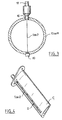
- Resistive son 1 and 2 are for example constituted by a driver resistive folded at 180 ° at its lower end and extending in duplicate in a sheath.
- the lower end of said wire 1 or 2 is set in a ring cylindrical 20 welded in a piercing body 10 or its branch 11.
- the resistive wire passes through electrically insulating a central bore of a mount 16 fixed in a another piercing of the body 10 or of the arm 11 by welding, said wire 1 or 2 being fixed to said mount 16.
- a connector 12 for connecting said wire 12 to the electronic management unit 30.
- heating of the resistive wire 1 or 2 is established by applying well defined current pulses and we study the slope of the wire cooling curve when between impulses successive, only a weak current, not significant, crosses it.
- Knowing this slope allows the processing unit 30 to calculate the mass flow rate of the fluid, said slope being in fact directly function of said mass flow.
- the electronic circuit of the flowmeter is designed so that the unit of command 30 can know at any time on the one hand the voltage U to terminals of the wire 1 or 2, and secondly the current I which passes through it.
- We can deduce the instantaneous value of its resistance R U / l, and therefore the instantaneous value of its temperature, the resistance varying according to the temperature according to a monotonous law that we know beforehand.
- the flow meter does not require any reference, unlike the majority of previously known systems.
- the flowmeter is insensitive to temperature variations of the fluid whose flow is to be measured.
- the unit 30 comprises means timed to apply over the pulses of current, with each time the same constant value of current, according to a well-defined cyclical ratio. It also includes means capable, during each period separating two pulses of successive currents, to acquire the temperature of the wire by measuring its resistance. In order to carry out this measurement, it is necessary to circulate a very small constant current in the wire, the value of this current being chosen so as not to influence the thermal behavior of the wire while cooling. For example, the current is chosen from to release a power of a few milliwatts, compared to a few tens of watts during the current pulses properly say. So the temperature of the wire during its cooling is directly proportional to the voltage at its terminals.
- the unit 30 comprises a branch circuit of this voltage in function of time.
- the derivative thus obtained is a function of flow mass and the processing unit 30 comprises conversion means which determine the mass flow as a function of the derivative of the voltage.
- the unit 30 includes memory means in which which conversion tables are stored.
- the son 1 and 2 of the flow meter can be received in a profile of the type of the one that has been described in the patent application FR 91 10845 of the applicant, to which one can advantageously refer.
- Such a profiled body has been shown in FIG. 4 on which it has been referenced by C. It has a wing-like shape that can be or not symmetrical.
- An opening O passes through said profiled body C the wire extending in the length of this opening.
- the shape of said opening O and the incidence of said body benefited C in the fluid flow being such that the boundary layer and the flow to be measured penetrate into said opening O so as to avoid or reduce the impacts particles, liquid or solid in the case of a gaseous fluid; solid in the case of a liquid fluid.
- the mass flowmeter which has just been described is particularly advantageous in the case of measurement on kerosene, in particular in the case of engine power supply or aircraft turbine.
Landscapes
- Physics & Mathematics (AREA)
- Fluid Mechanics (AREA)
- General Physics & Mathematics (AREA)
- Measuring Volume Flow (AREA)
- Thermistors And Varistors (AREA)
- Investigating Or Analyzing Materials By The Use Of Fluid Adsorption Or Reactions (AREA)
Description
- la figure 1 est une représentation schématique en coupe d'un débitmètre conforme à un mode de réalisation de l'invention vue en coupe verticale axiale d'un débitmètre massique à fil chaud ;
- la figure 2 est une représentation schématique illustrant le montage d'un fil résistif ;
- la figure 3 est une vue en coupe transversal du montage de la figure 2,
- la figure 4 est une représentation schématique en perspective d'un corps de profité dans lequel le fil d'un débitmètre conforme à l'invention peut être reçu.
Claims (5)
- Débitmètre massique, du type comprenant au moins un fil résistif chauffant (1 ou 2) placé sur le trajet d'un fluide dont on souhaite mesurer le débit, des moyens (30) pour appliquer audit fil des impulsions de courant de chauffage, des moyens de mesure pour déterminer sa vitesse de refroidissement entre lesdites impulsions et en déduire un débit massique, caractérisé en ce qu'il comporte deux tels fils résistifs (1, 2) qui s'étendent au niveau de deux zones de passages de fluide dont les sections desdits passages étant dans un rapport donné et en ce qu'il comporte des moyens de traitement aptes d'une part à déterminer des mesures de débits massiques pour chacun desdits deux fils et d'autre part à comparer le rapport des mesures obtenues avec l'un et l'autre des deux fils résistifs à un rapport théoriquement attendu fonction du rapport donné entre les sections de passage. les moyens de traitement étant aptes à déduire de cette comparaison ainsi que d'au moins l'une des vitesses de refroidissement mesurée d'une part le type de fluide circulant et d'autre part le débit massique du fluide.
- Débitmètre massique selon la revendication 1, caractérisé en ce que les zones de passage de fluide sont un corps creux dans lequel circule le fluide et une branche qui est une dérivation par rapport audit corps creux.
- Débitmètre massique selon l'une des revendications précédentes, caractérisé en ce qu'il comporte un corps profilé (C) de type aile d'avion et en ce qu'une ouverture (O) traverse ledit corps profilé (C), un fil métallique de chauffage s'étendant dans la longueur de cette ouverture, la forme de ladite ouverture (O) et l'incidence dudit corps profilé (C) dans le flux de fluide étant telles que la couche limite et le flux à mesurer pénètrent dans ladite ouverture (O) de façon à éviter ou réduire les impacts de particules sur le fil.
- Débitmètre massique selon l'une des revendications précédentes, caractérisé en ce que le fluide est du kérosène, les moyens de traitement étant aptes à déduire de la comparaison mise en oeuvre le type de kérosène circulant.
- Débitmètre massique pour la mesure d'un débit massique de kérosène dans un aéronef, caractérisé en ce qu'il est constitué par un débitmètre selon l'une des revendications précédentes.
Applications Claiming Priority (3)
| Application Number | Priority Date | Filing Date | Title |
|---|---|---|---|
| FR9905986A FR2793554B1 (fr) | 1999-05-11 | 1999-05-11 | Perfectionnements aux debitmetres massiques du type a fil resistif |
| FR9905986 | 1999-05-11 | ||
| PCT/FR2000/001254 WO2000068650A1 (fr) | 1999-05-11 | 2000-05-10 | Perfectionnements aux debitmetres massiques du type a fil resistif |
Publications (2)
| Publication Number | Publication Date |
|---|---|
| EP1177414A1 EP1177414A1 (fr) | 2002-02-06 |
| EP1177414B1 true EP1177414B1 (fr) | 2005-02-02 |
Family
ID=9545452
Family Applications (1)
| Application Number | Title | Priority Date | Filing Date |
|---|---|---|---|
| EP00925423A Expired - Lifetime EP1177414B1 (fr) | 1999-05-11 | 2000-05-10 | Perfectionnements aux debitmetres massiques du type a fil resistif |
Country Status (10)
| Country | Link |
|---|---|
| US (1) | US6601448B1 (fr) |
| EP (1) | EP1177414B1 (fr) |
| JP (1) | JP2002544499A (fr) |
| AT (1) | ATE288580T1 (fr) |
| CA (1) | CA2373533A1 (fr) |
| DE (1) | DE60017890T2 (fr) |
| ES (1) | ES2234594T3 (fr) |
| FR (1) | FR2793554B1 (fr) |
| PT (1) | PT1177414E (fr) |
| WO (1) | WO2000068650A1 (fr) |
Families Citing this family (2)
| Publication number | Priority date | Publication date | Assignee | Title |
|---|---|---|---|---|
| JP4820815B2 (ja) * | 2004-03-16 | 2011-11-24 | オーチス エレベータ カンパニー | エレベータ荷重支持部材の状態を監視する電気信号適用方法 |
| WO2014008337A1 (fr) * | 2012-07-03 | 2014-01-09 | David Bradin | Procédé de fabrication de compositions de carburéacteur renouvelable |
Family Cites Families (6)
| Publication number | Priority date | Publication date | Assignee | Title |
|---|---|---|---|---|
| US3363463A (en) * | 1965-02-15 | 1968-01-16 | California Inst Res Found | Means of directionally sensing flow |
| JPS58501094A (ja) * | 1981-07-13 | 1983-07-07 | バテル メモリアル インステイチユ−ト | 流体中に浸漬された探査子の熱交換と関連する該流体の少なくとも1つの瞬時的パラメ−タを算定する方法及び該方法を実行するための装置 |
| US4604895A (en) * | 1983-05-02 | 1986-08-12 | Air Sensor Inc. | Hot wire anemometer |
| DE3527868A1 (de) * | 1985-08-02 | 1987-02-12 | Schmidt Feintechnik Gmbh | Verfahren und messsonde zum sondieren des fuellstandes des massenstromes, der fluidart, der fluidzusammensetzung oder dgl. in einem eine oder mehrere fluids enthaltenden behaelter, leitungen oder dgl. |
| WO1989001132A1 (fr) * | 1987-07-27 | 1989-02-09 | Solid State Flowmeters Pty Ltd | Mesurage de l'ecoulement d'un fluide par chauffage de semi-conducteurs |
| FR2680872A1 (fr) * | 1991-09-02 | 1993-03-05 | Auxitrol Sa | Sonde pour la mesure de parametres physiques d'un flux de fluide. |
-
1999
- 1999-05-11 FR FR9905986A patent/FR2793554B1/fr not_active Expired - Fee Related
-
2000
- 2000-05-10 PT PT00925423T patent/PT1177414E/pt unknown
- 2000-05-10 AT AT00925423T patent/ATE288580T1/de not_active IP Right Cessation
- 2000-05-10 DE DE60017890T patent/DE60017890T2/de not_active Expired - Fee Related
- 2000-05-10 US US09/979,606 patent/US6601448B1/en not_active Expired - Fee Related
- 2000-05-10 ES ES00925423T patent/ES2234594T3/es not_active Expired - Lifetime
- 2000-05-10 CA CA002373533A patent/CA2373533A1/fr not_active Abandoned
- 2000-05-10 JP JP2000617392A patent/JP2002544499A/ja active Pending
- 2000-05-10 WO PCT/FR2000/001254 patent/WO2000068650A1/fr not_active Ceased
- 2000-05-10 EP EP00925423A patent/EP1177414B1/fr not_active Expired - Lifetime
Also Published As
| Publication number | Publication date |
|---|---|
| US6601448B1 (en) | 2003-08-05 |
| FR2793554A1 (fr) | 2000-11-17 |
| PT1177414E (pt) | 2005-06-30 |
| FR2793554B1 (fr) | 2001-08-10 |
| JP2002544499A (ja) | 2002-12-24 |
| DE60017890T2 (de) | 2005-12-29 |
| EP1177414A1 (fr) | 2002-02-06 |
| ES2234594T3 (es) | 2005-07-01 |
| CA2373533A1 (fr) | 2000-11-16 |
| DE60017890D1 (de) | 2005-03-10 |
| WO2000068650A1 (fr) | 2000-11-16 |
| ATE288580T1 (de) | 2005-02-15 |
Similar Documents
| Publication | Publication Date | Title |
|---|---|---|
| EP0070801A1 (fr) | Procédé pour déterminer au moins un paramètre instantané d'un fluide lié à l'échange thermique d'une sonde immergée dans ce fluide et dispositif pour la mise en oeuvre de ce procédé | |
| FR2530014A1 (fr) | Procede et dispositif de mesure thermique du debit-masse | |
| EP0566479A1 (fr) | Dispositif de détection d'encrassement d'un filtre à air | |
| FR2539869A1 (fr) | Debitmetre de masse thermique, notamment pour gaz | |
| CH638618A5 (fr) | Capteur anemometrique directionnel a perte de chaleur. | |
| FR2527330A1 (fr) | Procede pour mesurer la masse d'air pulsatoire aspiree par un moteur a combustion interne | |
| EP0023457A1 (fr) | Procédé de mesure de vitesse d'écoulement d'un fluide par détermination de la durée de transit d'un marqueur, et débitmètre fondé sur ce procédé | |
| EP1886116A2 (fr) | Methode et systeme pour la mesure et l'etude de l'encrassement d'un reacteur | |
| FR2680872A1 (fr) | Sonde pour la mesure de parametres physiques d'un flux de fluide. | |
| FR2548329A1 (fr) | Dispositif de commande de debits calibres de fluide | |
| CA2373533A1 (fr) | Perfectionnements aux debitmetres massiques du type a fil resistif | |
| EP0183615A2 (fr) | Procédé et dispositif de détection de changement de phase | |
| FR2602870A1 (fr) | Procede pour regenerer des cellules de mesure potentiometrique a electrolyte solide et dispositif de raccordement sur une cellule de mesure | |
| EP1177415B1 (fr) | Debitmetres massiques du type a fil resistif | |
| FR2713765A1 (fr) | Procédé pour mesurer une masse d'air aspirée. | |
| WO2014202476A1 (fr) | Dispositif pour absorber une puissance optique | |
| FR2558954A1 (fr) | Calorimetre | |
| CH624486A5 (fr) | ||
| FR2749660A1 (fr) | Procede et appareil de mesure de la temperature et de la composition d'un melange de gaz | |
| CH651388A5 (fr) | Debimetre pour la mesure de la vitesse d'ecoulement d'un fluide. | |
| FR2476305A1 (fr) | Dispositif pour mesurer la masse d'un fluide en mouvement | |
| FR2503863A1 (fr) | Equipement de mesure des quantites de chaleur dans les divers corps de chauffe d'une centrale commune | |
| FR2817351A1 (fr) | Procede et dispositif de mesure thermique d'une acceleration | |
| WO2013160612A1 (fr) | Correction d'une mesure de température d'une sonde de température de type à résistance thermométrique | |
| FR2855261A1 (fr) | Capteur de passage a deux resistances |
Legal Events
| Date | Code | Title | Description |
|---|---|---|---|
| PUAI | Public reference made under article 153(3) epc to a published international application that has entered the european phase |
Free format text: ORIGINAL CODE: 0009012 |
|
| 17P | Request for examination filed |
Effective date: 20011203 |
|
| AK | Designated contracting states |
Kind code of ref document: A1 Designated state(s): AT BE CH CY DE DK ES FI FR GB GR IE IT LI LU MC NL PT SE |
|
| RAP1 | Party data changed (applicant data changed or rights of an application transferred) |
Owner name: AUXITROL SA |
|
| GRAP | Despatch of communication of intention to grant a patent |
Free format text: ORIGINAL CODE: EPIDOSNIGR1 |
|
| GRAS | Grant fee paid |
Free format text: ORIGINAL CODE: EPIDOSNIGR3 |
|
| GRAA | (expected) grant |
Free format text: ORIGINAL CODE: 0009210 |
|
| AK | Designated contracting states |
Kind code of ref document: B1 Designated state(s): AT BE CH CY DE DK ES FI FR GB GR IE IT LI LU MC NL PT SE |
|
| REG | Reference to a national code |
Ref country code: GB Ref legal event code: FG4D Free format text: NOT ENGLISH |
|
| REG | Reference to a national code |
Ref country code: CH Ref legal event code: EP |
|
| REG | Reference to a national code |
Ref country code: IE Ref legal event code: FG4D Free format text: FRENCH |
|
| REF | Corresponds to: |
Ref document number: 60017890 Country of ref document: DE Date of ref document: 20050310 Kind code of ref document: P |
|
| REG | Reference to a national code |
Ref country code: CH Ref legal event code: NV Representative=s name: MICHELI & CIE INGENIEURS-CONSEILS |
|
| REG | Reference to a national code |
Ref country code: GR Ref legal event code: EP Ref document number: 20050400728 Country of ref document: GR |
|
| GBT | Gb: translation of ep patent filed (gb section 77(6)(a)/1977) |
Effective date: 20050330 |
|
| PGFP | Annual fee paid to national office [announced via postgrant information from national office to epo] |
Ref country code: DK Payment date: 20050429 Year of fee payment: 6 |
|
| REG | Reference to a national code |
Ref country code: SE Ref legal event code: TRGR |
|
| PGFP | Annual fee paid to national office [announced via postgrant information from national office to epo] |
Ref country code: FR Payment date: 20050516 Year of fee payment: 6 |
|
| PGFP | Annual fee paid to national office [announced via postgrant information from national office to epo] |
Ref country code: FI Payment date: 20050517 Year of fee payment: 6 Ref country code: MC Payment date: 20050517 Year of fee payment: 6 Ref country code: IE Payment date: 20050517 Year of fee payment: 6 |
|
| PGFP | Annual fee paid to national office [announced via postgrant information from national office to epo] |
Ref country code: ES Payment date: 20050518 Year of fee payment: 6 Ref country code: GR Payment date: 20050518 Year of fee payment: 6 Ref country code: GB Payment date: 20050518 Year of fee payment: 6 |
|
| PGFP | Annual fee paid to national office [announced via postgrant information from national office to epo] |
Ref country code: PT Payment date: 20050519 Year of fee payment: 6 |
|
| PGFP | Annual fee paid to national office [announced via postgrant information from national office to epo] |
Ref country code: AT Payment date: 20050523 Year of fee payment: 6 |
|
| PGFP | Annual fee paid to national office [announced via postgrant information from national office to epo] |
Ref country code: SE Payment date: 20050531 Year of fee payment: 6 Ref country code: NL Payment date: 20050531 Year of fee payment: 6 Ref country code: DE Payment date: 20050531 Year of fee payment: 6 Ref country code: CY Payment date: 20050531 Year of fee payment: 6 |
|
| REG | Reference to a national code |
Ref country code: DK Ref legal event code: T3 |
|
| PGFP | Annual fee paid to national office [announced via postgrant information from national office to epo] |
Ref country code: CH Payment date: 20050608 Year of fee payment: 6 |
|
| PGFP | Annual fee paid to national office [announced via postgrant information from national office to epo] |
Ref country code: BE Payment date: 20050609 Year of fee payment: 6 |
|
| PGFP | Annual fee paid to national office [announced via postgrant information from national office to epo] |
Ref country code: LU Payment date: 20050610 Year of fee payment: 6 |
|
| REG | Reference to a national code |
Ref country code: PT Ref legal event code: SC4A Free format text: AVAILABILITY OF NATIONAL TRANSLATION Effective date: 20050419 |
|
| REG | Reference to a national code |
Ref country code: ES Ref legal event code: FG2A Ref document number: 2234594 Country of ref document: ES Kind code of ref document: T3 |
|
| PLBE | No opposition filed within time limit |
Free format text: ORIGINAL CODE: 0009261 |
|
| STAA | Information on the status of an ep patent application or granted ep patent |
Free format text: STATUS: NO OPPOSITION FILED WITHIN TIME LIMIT |
|
| 26N | No opposition filed |
Effective date: 20051103 |
|
| PG25 | Lapsed in a contracting state [announced via postgrant information from national office to epo] |
Ref country code: IE Free format text: LAPSE BECAUSE OF NON-PAYMENT OF DUE FEES Effective date: 20060510 Ref country code: GB Free format text: LAPSE BECAUSE OF NON-PAYMENT OF DUE FEES Effective date: 20060510 Ref country code: FI Free format text: LAPSE BECAUSE OF NON-PAYMENT OF DUE FEES Effective date: 20060510 Ref country code: CY Free format text: LAPSE BECAUSE OF NON-PAYMENT OF DUE FEES Effective date: 20060510 Ref country code: AT Free format text: LAPSE BECAUSE OF NON-PAYMENT OF DUE FEES Effective date: 20060510 |
|
| PG25 | Lapsed in a contracting state [announced via postgrant information from national office to epo] |
Ref country code: SE Free format text: LAPSE BECAUSE OF NON-PAYMENT OF DUE FEES Effective date: 20060511 Ref country code: ES Free format text: LAPSE BECAUSE OF NON-PAYMENT OF DUE FEES Effective date: 20060511 |
|
| PG25 | Lapsed in a contracting state [announced via postgrant information from national office to epo] |
Ref country code: MC Free format text: LAPSE BECAUSE OF NON-PAYMENT OF DUE FEES Effective date: 20060531 Ref country code: LI Free format text: LAPSE BECAUSE OF NON-PAYMENT OF DUE FEES Effective date: 20060531 Ref country code: DK Free format text: LAPSE BECAUSE OF NON-PAYMENT OF DUE FEES Effective date: 20060531 Ref country code: CH Free format text: LAPSE BECAUSE OF NON-PAYMENT OF DUE FEES Effective date: 20060531 Ref country code: BE Free format text: LAPSE BECAUSE OF NON-PAYMENT OF DUE FEES Effective date: 20060531 |
|
| PGFP | Annual fee paid to national office [announced via postgrant information from national office to epo] |
Ref country code: IT Payment date: 20060531 Year of fee payment: 7 |
|
| PG25 | Lapsed in a contracting state [announced via postgrant information from national office to epo] |
Ref country code: PT Free format text: LAPSE BECAUSE OF NON-PAYMENT OF DUE FEES Effective date: 20061110 |
|
| PG25 | Lapsed in a contracting state [announced via postgrant information from national office to epo] |
Ref country code: NL Free format text: LAPSE BECAUSE OF NON-PAYMENT OF DUE FEES Effective date: 20061201 Ref country code: DE Free format text: LAPSE BECAUSE OF NON-PAYMENT OF DUE FEES Effective date: 20061201 |
|
| REG | Reference to a national code |
Ref country code: PT Ref legal event code: MM4A Free format text: LAPSE DUE TO NON-PAYMENT OF FEES Effective date: 20061110 |
|
| REG | Reference to a national code |
Ref country code: CH Ref legal event code: PL Ref country code: DK Ref legal event code: EBP |
|
| EUG | Se: european patent has lapsed | ||
| GBPC | Gb: european patent ceased through non-payment of renewal fee |
Effective date: 20060510 |
|
| NLV4 | Nl: lapsed or anulled due to non-payment of the annual fee |
Effective date: 20061201 |
|
| REG | Reference to a national code |
Ref country code: IE Ref legal event code: MM4A |
|
| REG | Reference to a national code |
Ref country code: FR Ref legal event code: ST Effective date: 20070131 |
|
| REG | Reference to a national code |
Ref country code: ES Ref legal event code: FD2A Effective date: 20060511 |
|
| BERE | Be: lapsed |
Owner name: S.A. *AUXITROL Effective date: 20060531 |
|
| PG25 | Lapsed in a contracting state [announced via postgrant information from national office to epo] |
Ref country code: FR Free format text: LAPSE BECAUSE OF NON-PAYMENT OF DUE FEES Effective date: 20060531 |
|
| PG25 | Lapsed in a contracting state [announced via postgrant information from national office to epo] |
Ref country code: LU Free format text: LAPSE BECAUSE OF NON-PAYMENT OF DUE FEES Effective date: 20060510 |
|
| PG25 | Lapsed in a contracting state [announced via postgrant information from national office to epo] |
Ref country code: GR Free format text: LAPSE BECAUSE OF NON-PAYMENT OF DUE FEES Effective date: 20061205 |
|
| PG25 | Lapsed in a contracting state [announced via postgrant information from national office to epo] |
Ref country code: IT Free format text: LAPSE BECAUSE OF NON-PAYMENT OF DUE FEES Effective date: 20070510 |