EP1176811A2 - Electronic camera - Google Patents
Electronic camera Download PDFInfo
- Publication number
- EP1176811A2 EP1176811A2 EP01306376A EP01306376A EP1176811A2 EP 1176811 A2 EP1176811 A2 EP 1176811A2 EP 01306376 A EP01306376 A EP 01306376A EP 01306376 A EP01306376 A EP 01306376A EP 1176811 A2 EP1176811 A2 EP 1176811A2
- Authority
- EP
- European Patent Office
- Prior art keywords
- time
- image data
- volatile memory
- maintain
- battery
- Prior art date
- Legal status (The legal status is an assumption and is not a legal conclusion. Google has not performed a legal analysis and makes no representation as to the accuracy of the status listed.)
- Withdrawn
Links
Images


Classifications
-
- H—ELECTRICITY
- H04—ELECTRIC COMMUNICATION TECHNIQUE
- H04N—PICTORIAL COMMUNICATION, e.g. TELEVISION
- H04N1/00—Scanning, transmission or reproduction of documents or the like, e.g. facsimile transmission; Details thereof
- H04N1/0035—User-machine interface; Control console
- H04N1/00405—Output means
- H04N1/00408—Display of information to the user, e.g. menus
-
- H—ELECTRICITY
- H04—ELECTRIC COMMUNICATION TECHNIQUE
- H04N—PICTORIAL COMMUNICATION, e.g. TELEVISION
- H04N1/00—Scanning, transmission or reproduction of documents or the like, e.g. facsimile transmission; Details thereof
- H04N1/00002—Diagnosis, testing or measuring; Detecting, analysing or monitoring not otherwise provided for
- H04N1/00026—Methods therefor
- H04N1/00068—Calculating or estimating
-
- H—ELECTRICITY
- H04—ELECTRIC COMMUNICATION TECHNIQUE
- H04N—PICTORIAL COMMUNICATION, e.g. TELEVISION
- H04N1/00—Scanning, transmission or reproduction of documents or the like, e.g. facsimile transmission; Details thereof
- H04N1/0035—User-machine interface; Control console
- H04N1/00405—Output means
- H04N1/00477—Indicating status, e.g. of a job
-
- H—ELECTRICITY
- H04—ELECTRIC COMMUNICATION TECHNIQUE
- H04N—PICTORIAL COMMUNICATION, e.g. TELEVISION
- H04N1/00—Scanning, transmission or reproduction of documents or the like, e.g. facsimile transmission; Details thereof
- H04N1/00885—Power supply means, e.g. arrangements for the control of power supply to the apparatus or components thereof
- H04N1/00899—Detection of supply level or supply failure
-
- H—ELECTRICITY
- H04—ELECTRIC COMMUNICATION TECHNIQUE
- H04N—PICTORIAL COMMUNICATION, e.g. TELEVISION
- H04N1/00—Scanning, transmission or reproduction of documents or the like, e.g. facsimile transmission; Details thereof
- H04N1/21—Intermediate information storage
- H04N1/2104—Intermediate information storage for one or a few pictures
- H04N1/2112—Intermediate information storage for one or a few pictures using still video cameras
-
- H—ELECTRICITY
- H04—ELECTRIC COMMUNICATION TECHNIQUE
- H04N—PICTORIAL COMMUNICATION, e.g. TELEVISION
- H04N1/00—Scanning, transmission or reproduction of documents or the like, e.g. facsimile transmission; Details thereof
- H04N1/21—Intermediate information storage
- H04N1/2104—Intermediate information storage for one or a few pictures
- H04N1/2112—Intermediate information storage for one or a few pictures using still video cameras
- H04N1/2137—Intermediate information storage for one or a few pictures using still video cameras with temporary storage before final recording, e.g. in a frame buffer
-
- H—ELECTRICITY
- H04—ELECTRIC COMMUNICATION TECHNIQUE
- H04N—PICTORIAL COMMUNICATION, e.g. TELEVISION
- H04N23/00—Cameras or camera modules comprising electronic image sensors; Control thereof
- H04N23/60—Control of cameras or camera modules
- H04N23/63—Control of cameras or camera modules by using electronic viewfinders
- H04N23/633—Control of cameras or camera modules by using electronic viewfinders for displaying additional information relating to control or operation of the camera
- H04N23/634—Warning indications
-
- H—ELECTRICITY
- H04—ELECTRIC COMMUNICATION TECHNIQUE
- H04N—PICTORIAL COMMUNICATION, e.g. TELEVISION
- H04N23/00—Cameras or camera modules comprising electronic image sensors; Control thereof
- H04N23/60—Control of cameras or camera modules
- H04N23/65—Control of camera operation in relation to power supply
-
- H—ELECTRICITY
- H04—ELECTRIC COMMUNICATION TECHNIQUE
- H04N—PICTORIAL COMMUNICATION, e.g. TELEVISION
- H04N1/00—Scanning, transmission or reproduction of documents or the like, e.g. facsimile transmission; Details thereof
- H04N1/00885—Power supply means, e.g. arrangements for the control of power supply to the apparatus or components thereof
-
- H—ELECTRICITY
- H04—ELECTRIC COMMUNICATION TECHNIQUE
- H04N—PICTORIAL COMMUNICATION, e.g. TELEVISION
- H04N2101/00—Still video cameras
Definitions
- the present invention relates to an electronic camera having a volatile memory in which image data can be temporarily recorded.
- Some conventional electronic cameras incorporate a buffer memory to allow continuous shooting and the like.
- a volatile memory is often used as such a buffer memory because of limitations on the cost, memory capacity, and so on.
- Image data temporarily recorded in a buffer memory is subjected to predetermined image processing and is thereafter transferred to and recorded in a data recording medium (hereinafter simply referred to as "medium") that is detachably attached to the electronic camera.
- the image data in the buffer memory is erased once it is transferred to and recorded in the medium.
- a conventional electronic camera has been controlled to indicate that the number of images that can be recorded in the medium is 0 and to disable the photographic operation of the camera when the remaining capacity of the medium falls below a capacity to accommodate the data of one image.
- the photographic operation is disabled until the medium full of image data is replaced with another medium, a problem has arisen in that a shooting opportunity can be missed because of time-consuming replacement.
- An electronic camera has a volatile memory for temporarily maintaining image data, a detection means for detecting the remaining capacity of a battery for supplying power to the volatile memory, and a maintain time calculating means for calculating a maintainable time for which the image data can be maintained in the volatile memory based on the remaining capacity of the battery detected by the detection means.
- a display of the maintainable time will make it easy to indicate until when the image data maintained in the volatile memory is to be transferred to and preserved in an external memory, e.g., a recording medium such as a memory card.
- Another electronic camera has a volatile memory for temporarily maintaining image data, a detection means for detecting the remaining capacity of a battery for supplying power to the volatile memory, a setting means for setting a desired data maintain time for the volatile memory in which the image data is maintained, a maintain capacity calculating means for calculating a maintain capacity that is a battery capacity to allow the image data to be maintained for the desired data maintain time, and an enabled time calculating means for calculating a time during which the camera is enabled based on a capacity difference obtained by subtracting the maintain capacity from the remaining capacity of the battery.
- the camera enabled time may be displayed on a display.
- a maintain time calculating means for calculating a maintainable time of the image data maintained in the volatile memory based on the remaining capacity of the battery detected by the detection means.
- the display preferably displays the camera enabled time and the maintainable time.
- the desired data maintain time is preferably displayed along with the camera enabled time.
- a preset desired data maintain time can be confirmed, and it is easy to know whether a desired data maintain time has been properly set as needed or not.
- Another electronic camera has a volatile memory which is an internal memory for temporarily maintaining image data to be transferred to an external memory of the camera, e.g., a recording medium that can be attached to and detached from the camera, a detection means for detecting the remaining capacity of a battery for supplying power to the volatile memory, a maintain time calculating means for calculating a maintainable time of the image data recorded in the volatile memory, a recording mode selecting means for selecting a first recording mode for transferring and recording the image data to the external memory after maintaining the image data in the volatile memory temporarily and a second recording mode for recording the image data in the volatile memory, and a display for displaying the maintainable time when the second recording mode is selected by the recording mode selecting means.
- a volatile memory which is an internal memory for temporarily maintaining image data to be transferred to an external memory of the camera, e.g., a recording medium that can be attached to and detached from the camera
- a detection means for detecting the remaining capacity of a battery for supplying power to the volatile memory
- a maintain time calculating means
- image data can be recorded in the volatile memory, for example, even when there is no memory card to serve as the external memory or even when the external memory is full of image data. As a result, a shooting opportunity will not be missed unlike the prior art.
- the electronic camera may have a setting means for setting a desired data maintain time for the volatile memory in which image data is maintained, a maintain capacity calculating means for calculating a maintain capacity that is a battery capacity to allow image data to be maintained for the maintain time, and an enabled time calculating means for calculating a camera enabled time based on a capacity difference obtained by subtracting the maintain capacity from the remaining capacity of the battery.
- the display displays the camera enabled time and the maintainable time. For example, such an electronic camera allows a photographic operation to be performed in consideration to the time required for moving to a place where image data can be preserved after the photographic operation.
- the above-described electronic camera further has a disabling means for disabling operations of the camera other than the maintenance of image data recorded in the volatile memory when the remaining capacity of the battery is equal to or smaller than the maintain capacity.
- a disabling means for disabling operations of the camera other than the maintenance of image data recorded in the volatile memory when the remaining capacity of the battery is equal to or smaller than the maintain capacity.
- Another electronic camera has a volatile memory for temporarily maintaining image data, a detection means for detecting the remaining capacity of a battery for supplying power to the volatile memory, a maintain time calculating means for calculating a maintainable time of the image data maintained in the volatile memory based on the remaining capacity of the battery detected by the detection means, an enabled time calculating means for calculating an enabled time of the camera based on the remaining capacity of the battery detected by the detection means, and a display for displaying the maintainable time and the camera enabled time.
- Fig. 1 is a block diagram showing a schematic configuration of an application of the invention to a digital still camera.
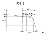
- Fig. 2 is a diagram that qualitatively shows relationship between the voltage of a battery 8 and a discharge capacity.
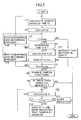
- Fig. 3 is a flow chart for explaining an operation of a camera.
- Fig. 4 is a flow chart that details the photographing and recording operation in the flow chart shown in Fig. 3.
- Fig. 1 is a diagram showing an embodiment of an electronic camera according to the invention, and it is a block diagram showing a schematic configuration of a digital still camera.
- An image pickup device 2 that is a CCD, CMOS image sensor or the like is provided behind a photographic lens 1 (or under the lens 1 in the figure), and subject light incident upon the photographic lens 1 forms an image on an image pickup surface of the image pickup device 2.
- An image signal output by the image pickup device 2 is converted by an A/D conversion circuit 3 into a digital signal which is then input to a signal processing circuit 4.
- the signal processing circuit 4 performs image processing such as contour compensation and gamma compensation on the digital signal thus converted.
- the image data which has been subjected to image processing such as gamma compensation at the signal processing circuit 4 is subjected to a reducing process or the like depending on the display resolution of an LCD monitor 5 and is displayed on the LCD monitor 5.
- the series of operations from the photographing at the image pickup device 2 up to the reducing process described above is repeated to update the image (referred to as "through image") displayed on the LCD monitor 5 sequentially at predetermined intervals.
- the focus of the photographic lens 1 is continually adjusted by an AF device which is not shown to display an image in focus on the LCD monitor 5.
- 6a and 6b represent a half-press switch and a full-press switch which are respectively associated with operations of pressing the release button of the electronic camera halfway and completely.
- the half-press switch 6a When the half-press switch 6a is turned on, the luminance of the subject is measured by a photometer which is not shown.
- the release button When the release button is thereafter pressed completely to turn the full-press switch 6b on, an image signal is output by the image pickup device 2.
- the image signal is converted by the A/D conversion circuit 3 into a digital signal which is then processed by the signal processing circuit 4 and is temporarily stored in a buffer memory 7.
- the buffer memory 7 is a volatile memory such as a DRAM. Data is maintained in the buffer memory 7 only when power is supplied from a battery 8, and the maintained data is lost when the supply of power is stopped. Image data stored in the buffer memory 7 is read into an image compression circuit 9 and is stored in the buffer memory 7 again after being subjected to a data compression process according to the JPEG compression method or the like. The image data stored in the buffer memory 7 is recorded in a recording medium 12 after date and time data, the shutter speed, and the stop value are added thereto.
- a volatile memory card such as a PC card or CF card is used as the recording medium 12.
- the recording medium is detachably attached to a connector 11 in a slot provided on the electronic camera.
- the recording medium may be replaced by an external memory to which image data is transferred through a cable or on a wireless basis.
- a CPU 10 which controls the camera as a whole calculates a maintainable time, a camera enabled time, a maintain capacity, and so on to be described later.
- the calculated times are displayed on a display section or a monitor 15.
- the display section 15 is supplied with power from a battery (not shown) that is provided separately from the battery 8 for driving the camera. This battery is used as a power source for a clock function and so on.
- a detecting section 16 for detecting the remaining capacity of the battery 8 calculates the remaining capacity based on the voltage V of the battery 8.
- 13 represents an interface circuit for connecting the connector 11 and CPU 10
- 14 represents an operating section for inputting various instructions (for mode setting, setting of a desired data maintain time, and so on to be described later) to the camera.
- the electronic camera of the present embodiment can record photographed image data in two modes.
- One is a mode in which data is recorded in the recording medium 12 in the same manner as that in a normal camera, and such setting is referred to as "normal mode”.
- the other is a mode in which image data is recorded and maintained in the buffer memory 7 provided inside the camera and which is referred to as "internal recording mode”. Selection between those modes may be automatically carried out by the camera depending on whether the recording medium 12 is full of image data or whether the recording medium 12 is attached or not, and the selection may alternatively be made by the photographer through an operation on the operating section 14.
- photographing can be carried out even if no recording medium 12 is attached to the camera or even if a recording medium 12 that is attached is full of image data, and the photographed image data is entirely recorded in the buffer memory 7.
- the CPU 10 calculates how long the image data recorded in the buffer memory 7 can be maintained by the remaining capacity of the battery 8. A maintainable time t1 thus calculated is displayed on the display section 15.
- Fig. 2 is a diagram that qualitatively shows relationship between the voltage V of the battery 8 and a discharge capacity Wh.
- the voltage V is 0 when the discharge capacity is 0.
- the voltage V linearly decreases as the discharge capacity increases, and the voltage drop abruptly increases near the end of discharge when the remaining capacity approaches zero.
- Vmin represents a lower limit of voltages at which a photographic operation and display of an image on the LCD monitor 5 are enabled, i.e., voltages at which the camera is enabled.
- the operation of the camera is disabled when the battery voltage is equal to or lower than Vmin.
- a data maintaining function for maintaining image data in the buffer memory 7 only works in the operation disabled state of the camera.
- Vmin represents a lower limit voltage to use the device as a camera.
- V1 ⁇ Vmin
- the remaining capacity ⁇ Wh of the battery is given by Equation (1) shown below.
- the power required for maintaining data is represented by W0
- the above-described maintainable time t1 is calculated according to Equation (2).
- a camera enabled time t2 calculated according to Equation (3) shown below may be displayed on the display section 15 along with the above-described maintainable time.
- W1 in Equation (3) represents power consumed to display images on the LCD monitor 5, and t2 represents a time for which images can be successively displayed.
- the number of images that can be photographed may be displayed instead of the camera enabled time t2.
- the number of images that can be photographed is obtained by dividing (Wh min - Wh2) by the amount Wh0 of power consumed to photograph one image.
- the camera enabled time t2 and the number of images that can be photographed may be displayed regardless of the above-described modes.
- t2 (Wh min - Wh2)/W1
- a desired maintain time can be set for image data maintained in the buffer memory 7.
- the setting operation is performed with the operating section 14. For example, when a time x is set as a desired data maintain time, the capacity required for maintaining the data for the time x (maintain capacity) is x ⁇ W0. When the battery voltage at the time of setting is V2, since the remaining capacity ⁇ Wh is given by Equation (1), a difference ⁇ Wh1 between the remaining capacity and the maintain capacity is given by Equation (4).
- the photographer can recognize how long the camera can be used from the indication of the time t3.
- the number of images that can be photographed which is calculated based on ⁇ Wh1/Wh0 may be displayed instead of the time t3.
- the remaining capacity ⁇ Wh becomes equal to x ⁇ W0 or when the battery voltage becomes V3 in Fig. 2
- operations of the camera are automatically disabled except the operation of maintaining image data in the buffer memory 7. Since the data is maintained for the time x after the disablement, the recording medium 12 is attached to the camera during that time to preserve the image data by transferring the image data to the same or transferring it from the camera to a personal computer or the like. At this time, the preserving operation is performed with power supplied to the camera using an AC adaptor or the like.
- Figs. 3 and 4 show a main routine and a sub-routine of the flow chart, respectively.
- the flow in Fig. 4 is started when the camera starts to be supplied with the power supply.
- step S1 the voltage V2 of the battery 8 is detected, and the camera enabled time t2 is calculated according to the above-described Equation (3) based on the voltage V2.
- step S2 the camera enabled time t2 calculated at step S1 is displayed on the display section 15.
- Step S3 is a step for judging whether the voltage V of the battery 8 is higher than the voltage Vmin that is the lowest voltage enabling photography by the camera.
- the process proceeds to step S4 when V is judged to be higher than Vmin, and the process proceeds to step S13 when V is judged to be equal to or lower than Vmin.
- step S13 the display unit 15 indicates that the battery 8 is empty and then the series of processes is terminated. It is judged at step S4 whether a desired maintain time has been set through an operation on the operating section 14. If yes, the process proceeds to step S14 and, if not, the process proceeds to step S5.
- step S5 the maintainable time t1 and the camera enabled time t3 are calculated according to Equations (2) and (5), and the times t1 and t3 and the set time x are displayed on the display section 15 at step S6.
- the camera enabled time t3 is the required time for which the battery voltage V2 at the present time decreases to V3 as shown in Fig. 2.
- V3 is the battery voltage at the time when data maintenance is started.
- step S7 it is judged whether the remaining capacity ⁇ Wh of the battery 8 is equal to or smaller than the maintain capacity x ⁇ W0 required for maintaining the image data or whether to start data maintenance. If it is judged that ⁇ Wh > x ⁇ W0 and that photographing is still enabled, the process proceeds to step S16. If it is judged that ⁇ Wh ⁇ x ⁇ W0 and that data maintenance is to be started, the process proceeds to step S8. When the process proceeds to step S8, CPU10 disables all functions other than the function of maintaining data. The process at step S16 will be described later.
- step S9 it is judged whether image data has been recorded in the buffer memory 7. If it is judged that no image data has been recorded, the series of operations is terminated without the operation of maintaining data. If it is judged that image data has been recorded, the process proceeds to step S10 to calculate the maintainable time t1. At step S11, it is judged whether the calculated maintainable time t1 is greater than 0 or whether a capacity to maintain the data is left. If it is judged that t1 > 0, the process proceeds to step S12 and, if it is judged that t1 ⁇ 0, the process proceeds to step S15.
- step S12 the display section 15 displays the maintainable time t1 and a indication or mark representing that the camera is disabled, and the process thereafter returns to step S10.
- step S15 the display section 15 displays a warning mark indicating that the data can not be maintained and then the series of operations is terminated. Referring to the alert indication at step S15, an LED or the like may be provided and blinked on the camera.
- Fig. 4 shows a subroutine that represents the process at step S16.
- step S20 it is judged whether a recording medium 12 is attached to the camera. If yes, the process proceeds to step S27 and, if not, the process proceeds to step S21.
- step S21 it is judged whether the buffer memory 7 is full of image data or whether no image data can be recorded in the buffer memory 7. If it is judged at step S21 that the memory is full of image data, the process exits the subroutine in Fig. 4 to proceed to step S10 in Fig. 3. If it is judged that there is a room for further recording, the process proceeds to step S22. It is judged at step S22 whether the full-press switch 6b in Fig. 2 has been turned on to perform a photographic operation. If a photographic operation has been performed, the process proceeds to step S23 to perform a photographic process. At step S24, the photographed image data is recorded in the buffer memory 7. If it is judged at step S22 that a photographic operation has not been performed, the process skips steps S23 and S24 to proceed to step S25.
- a maintainable time t1 is calculated according to Equation (2), and the maintainable time t1 is displayed on the display section 15 at step S26.
- the series of operations shown in Fig. 4 is terminated to return to the main routine in Fig. 3, and the process further returns to step S3 from step S16.
- step S14 When the process proceeds to step S14 based on a judgment at the above-described step S4 that a maintain time has been set, the process returns to step S1 after the photographing and recording processes shown in Fig. 4.
- the photographing and recording processes in Fig. 4 will not be described here because they have been described at step S16.
- step S27 If it is judged at step S27 that the recording medium 12 is full, the process proceeds to step S21. If the answer at step S27 is negative, the process proceeds to step S28. If it is judged at step S28 that a photographic operation is in progress, the process proceeds to step S29 to perform the above-described photographic process. Thereafter, the photographed image data is transferred to and recorded in the recording medium 12 at step S30. When the answer at step S28 is negative, the process returns to a predetermined step.
- an indication may be displayed on the display section 15 to indicate that no data can be preserved in the recording medium 12 or buffer memory 7.
- the camera of the present embodiment has the following advantages.
Landscapes
- Engineering & Computer Science (AREA)
- Multimedia (AREA)
- Signal Processing (AREA)
- Health & Medical Sciences (AREA)
- Biomedical Technology (AREA)
- General Health & Medical Sciences (AREA)
- Human Computer Interaction (AREA)
- Studio Devices (AREA)
- Indication In Cameras, And Counting Of Exposures (AREA)
- Cameras In General (AREA)
- Camera Bodies And Camera Details Or Accessories (AREA)
- Charge And Discharge Circuits For Batteries Or The Like (AREA)
Abstract
Description

Claims (10)
- An electronic camera comprising:a volatile memory for temporarily maintaining image data;a detection means for detecting a remaining capacity of a battery for supplying power to said volatile memory; anda maintain time calculating means for calculating a maintainable time of the image data maintained in said volatile memory based on the remaining capacity detected by said detection means.
- An electronic camera according to Claim 1, further comprising a display for displaying the maintainable time.
- An electronic camera comprising:a volatile memory for temporarily maintaining image data;a detection means for detecting a remaining capacity of a battery for supplying power to said volatile memory;a setting means for setting a desired data maintain time for said volatile memory in which the image data is maintained;a maintain capacity calculating means for calculating a maintain capacity that is a battery capacity to allow the image data to be maintained for the desired data maintain time; andan enabled time calculating means for calculating a time during which the camera is enabled based on a capacity difference obtained by subtracting the maintain capacity from the remaining capacity of the battery.
- An electronic camera according to Claim 3, further comprising a display for displaying the camera enabled time.
- An electronic camera according to Claim 4, further comprising a maintain time calculating means for calculating a maintainable time of the image data maintained in said volatile memory based on the remaining capacity of the battery detected by said detection means, wherein
said display displays the camera enabled time and the maintainable time. - An electronic camera according to Claim 4, wherein said display displays the desired data maintain time set by said setting means along with the camera enabled time.
- An electronic camera comprising:a volatile memory for temporarily maintaining image data to be transferred to an external memory of the camera;a detection means for detecting a remaining capacity of a battery for supplying power to said volatile memory;a maintain time calculating means for calculating a maintainable time of the image data recorded in said volatile memory based on the remaining capacity of the battery detected by said detection means;a recording mode selecting means for selecting a first recording mode for transferring and recording the image data to the external memory after maintaining the image data in said volatile memory temporarily and a second recording mode for recording the image data in said volatile memory; anda display for displaying the maintainable time when the second recording mode is selected by said recording mode selecting means.
- An electronic camera according to Claim7, further comprising:a setting means for setting a desired data maintain time for said volatile memory in which image data is maintained;a maintain capacity calculating means for calculating a maintain capacity that is a battery capacity to allow image data to be maintained for the desired maintain time; andan enabled time calculating means for calculating a camera enabled time based on a capacity difference obtained by subtracting the maintain capacity from the remaining capacity of the battery, said display displaying the camera enabled time and the maintainable time.
- An electronic camera according to any one of Claims 3 through 6 and Claim 8, further comprising a disabling means for disabling operations of the camera other than the maintenance of image data recorded in said volatile memory when the remaining capacity of the battery is equal to or smaller than the maintain capacity.
- An electronic camera comprising:a volatile memory for temporarily maintaining image data;a detection means for detecting a remaining capacity of a battery for supplying power to said volatile memory;a maintain time calculating means for calculating a maintainable time of the image data maintained in said volatile memory based on the remaining capacity of the battery detected by said detection means;an enabled time calculating means for calculating a camera enabled time based on the remaining capacity of the battery detected by said detection means; anda display for displaying the maintainable time and the camera enabled time.
Applications Claiming Priority (2)
| Application Number | Priority Date | Filing Date | Title |
|---|---|---|---|
| JP2000223446 | 2000-07-25 | ||
| JP2000223446A JP4423764B2 (en) | 2000-07-25 | 2000-07-25 | Electronic camera |
Publications (2)
| Publication Number | Publication Date |
|---|---|
| EP1176811A2 true EP1176811A2 (en) | 2002-01-30 |
| EP1176811A3 EP1176811A3 (en) | 2002-12-11 |
Family
ID=18717535
Family Applications (1)
| Application Number | Title | Priority Date | Filing Date |
|---|---|---|---|
| EP01306376A Withdrawn EP1176811A3 (en) | 2000-07-25 | 2001-07-25 | Electronic camera |
Country Status (3)
| Country | Link |
|---|---|
| US (1) | US7081924B2 (en) |
| EP (1) | EP1176811A3 (en) |
| JP (1) | JP4423764B2 (en) |
Cited By (2)
| Publication number | Priority date | Publication date | Assignee | Title |
|---|---|---|---|---|
| EP1367480A1 (en) * | 2002-05-29 | 2003-12-03 | AboCom Systems, Inc. | Portable computer capable of setting a data keeping time |
| CN1303813C (en) * | 2003-06-09 | 2007-03-07 | 佳能株式会社 | Data recording apparatus and data recording method |
Families Citing this family (33)
| Publication number | Priority date | Publication date | Assignee | Title |
|---|---|---|---|---|
| US7542091B2 (en) * | 2001-12-11 | 2009-06-02 | Hewlett-Packard Development Company, L.P. | Device power management method and apparatus |
| US20050062878A1 (en) | 2003-03-26 | 2005-03-24 | Nikon Corporation | Power system and camera |
| JP2005117479A (en) * | 2003-10-09 | 2005-04-28 | Canon Inc | Disc recording apparatus, disc recording method, and program |
| US7348761B2 (en) * | 2004-03-30 | 2008-03-25 | Seiko Epson Corporation | Information terminal and battery remaining capacity calculating method |
| JP4355250B2 (en) * | 2004-03-31 | 2009-10-28 | Hoya株式会社 | Digital camera |
| US20060171603A1 (en) * | 2005-01-31 | 2006-08-03 | Searete Llc, A Limited Liability Corporation Of The State Of Delaware | Resampling of transformed shared image techniques |
| US20060187230A1 (en) * | 2005-01-31 | 2006-08-24 | Searete Llc | Peripheral shared image device sharing |
| US20060190968A1 (en) * | 2005-01-31 | 2006-08-24 | Searete Llc, A Limited Corporation Of The State Of The State Of Delaware | Sharing between shared audio devices |
| US20060173972A1 (en) * | 2005-01-31 | 2006-08-03 | Searete Llc, A Limited Liability Corporation Of The State Of Delaware | Audio sharing |
| US9124729B2 (en) * | 2005-01-31 | 2015-09-01 | The Invention Science Fund I, Llc | Shared image device synchronization or designation |
| US9910341B2 (en) | 2005-01-31 | 2018-03-06 | The Invention Science Fund I, Llc | Shared image device designation |
| US20070236505A1 (en) * | 2005-01-31 | 2007-10-11 | Searete Llc, A Limited Liability Corporation Of The State Of Delaware | Resampling of transformed shared image techniques |
| US20060187228A1 (en) * | 2005-01-31 | 2006-08-24 | Searete Llc, A Limited Liability Corporation Of The State Of Delaware | Sharing including peripheral shared image device |
| US9082456B2 (en) * | 2005-01-31 | 2015-07-14 | The Invention Science Fund I Llc | Shared image device designation |
| US9489717B2 (en) | 2005-01-31 | 2016-11-08 | Invention Science Fund I, Llc | Shared image device |
| US20060187227A1 (en) * | 2005-01-31 | 2006-08-24 | Jung Edward K | Storage aspects for imaging device |
| US7920169B2 (en) * | 2005-01-31 | 2011-04-05 | Invention Science Fund I, Llc | Proximity of shared image devices |
| US20060174203A1 (en) * | 2005-01-31 | 2006-08-03 | Searete Llc, A Limited Liability Corporation Of The State Of Delaware | Viewfinder for shared image device |
| US7876357B2 (en) | 2005-01-31 | 2011-01-25 | The Invention Science Fund I, Llc | Estimating shared image device operational capabilities or resources |
| US20060285150A1 (en) * | 2005-01-31 | 2006-12-21 | Searete Llc, A Limited Liability Corporation Of The State Of Delaware | Regional proximity for shared image device(s) |
| US8902320B2 (en) * | 2005-01-31 | 2014-12-02 | The Invention Science Fund I, Llc | Shared image device synchronization or designation |
| US8606383B2 (en) * | 2005-01-31 | 2013-12-10 | The Invention Science Fund I, Llc | Audio sharing |
| US9001215B2 (en) * | 2005-06-02 | 2015-04-07 | The Invention Science Fund I, Llc | Estimating shared image device operational capabilities or resources |
| US9819490B2 (en) | 2005-05-04 | 2017-11-14 | Invention Science Fund I, Llc | Regional proximity for shared image device(s) |
| US10003762B2 (en) | 2005-04-26 | 2018-06-19 | Invention Science Fund I, Llc | Shared image devices |
| JP4650281B2 (en) * | 2006-01-20 | 2011-03-16 | 株式会社ニコン | Single-lens reflex electronic camera |
| JP5161443B2 (en) * | 2006-08-11 | 2013-03-13 | ペンタックスリコーイメージング株式会社 | camera |
| US7747900B2 (en) * | 2007-04-02 | 2010-06-29 | International Business Machines Corporation | Thresholding system power loss notifications in a data processing system based on vital product data |
| US7937602B2 (en) * | 2007-04-02 | 2011-05-03 | International Business Machines Corporation | System and method for thresholding system power loss notifications in a data processing system based on current distribution network configuration |
| JP2009100220A (en) * | 2007-10-16 | 2009-05-07 | Olympus Imaging Corp | Camera and camera system |
| US8190925B2 (en) | 2008-10-02 | 2012-05-29 | International Business Machines Corporation | Single shared power domain dynamic load based power loss detection and notification |
| JP2013128240A (en) * | 2011-12-19 | 2013-06-27 | Sanyo Electric Co Ltd | Electronic camera |
| JP7350616B2 (en) * | 2019-10-21 | 2023-09-26 | キヤノン株式会社 | Optical equipment control device and control method |
Family Cites Families (26)
| Publication number | Priority date | Publication date | Assignee | Title |
|---|---|---|---|---|
| US5018017A (en) * | 1987-12-25 | 1991-05-21 | Kabushiki Kaisha Toshiba | Electronic still camera and image recording method thereof |
| US5159458A (en) * | 1988-09-13 | 1992-10-27 | Canon Kabushiki Kaisha | Camera sensing when a memory cartridge is installed |
| US5153729A (en) * | 1988-10-24 | 1992-10-06 | Fuji Photo Film Co., Ltd. | Digital electronic still camera automatically determining conditions of a memory cartridge |
| JP2803132B2 (en) | 1989-02-27 | 1998-09-24 | キヤノン株式会社 | Solid camera |
| JP2712497B2 (en) | 1989-03-02 | 1998-02-10 | キヤノン株式会社 | Solid camera |
| JPH04241335A (en) * | 1991-01-14 | 1992-08-28 | Fuji Photo Film Co Ltd | Digital electronic still camera with voltage drop warning mechanism incorporated with memory card |
| JP3273471B2 (en) * | 1992-09-09 | 2002-04-08 | キヤノン株式会社 | Image recording device |
| US6067171A (en) | 1995-11-09 | 2000-05-23 | Brother Kogyo Kabushiki Kaisha | Portable communication apparatus |
| US6522361B2 (en) * | 1996-03-08 | 2003-02-18 | Sony Corporation | Electronic apparatus having the function of displaying the battery residual quantity and method for displaying the battery residual quantity |
| US5944829A (en) * | 1996-09-30 | 1999-08-31 | Intel Corporation | Adjusting software characteristics by user interface based upon battery level and the amount of time the user wants the battery to last |
| JPH10136574A (en) * | 1996-10-31 | 1998-05-22 | Hitachi Ltd | Battery control device |
| US6111608A (en) * | 1996-11-19 | 2000-08-29 | Konica Corporation | Electronic camera equipped with low-pass filter and lens system having resolving power |
| US6195754B1 (en) * | 1997-01-28 | 2001-02-27 | Tandem Computers Incorporated | Method and apparatus for tolerating power outages of variable duration in a multi-processor system |
| US6771896B2 (en) * | 1997-10-03 | 2004-08-03 | Konica Corporation | Electric camera with image printing system |
| US6079026A (en) * | 1997-12-11 | 2000-06-20 | International Business Machines Corporation | Uninterruptible memory backup power supply system using threshold value of energy in the backup batteries for control of switching from AC to DC output |
| JP4339423B2 (en) * | 1998-02-13 | 2009-10-07 | ソニー株式会社 | Battery pack, battery system, and charging control method for battery system |
| US7519268B2 (en) * | 1998-04-14 | 2009-04-14 | Nikon Corporation | Image recording apparatus, dynamic image processing apparatus, dynamic image reproduction apparatus, dynamic image recording apparatus, information recording / reproduction apparatus and methods employed therein, recording medium with computer program stored therein |
| JPH11341414A (en) * | 1998-05-29 | 1999-12-10 | Nikon Corp | Video recording camera and video playback device |
| US6051957A (en) * | 1998-10-21 | 2000-04-18 | Duracell Inc. | Battery pack having a state of charge indicator |
| CN1181676C (en) * | 1999-02-08 | 2004-12-22 | 三洋电机株式会社 | Moving image recording apparatus and digital camera |
| JP2000253303A (en) * | 1999-02-26 | 2000-09-14 | Minolta Co Ltd | Digital camera and electronic device driven by battery |
| US6137292A (en) * | 1999-05-03 | 2000-10-24 | Lucent Technologies, Inc. | Self-adjusting battery diagnostic method for continuously providing best prediction of battery reserve time |
| JP2000350374A (en) * | 1999-06-01 | 2000-12-15 | Sony Corp | Portable electronic devices |
| JP4362898B2 (en) * | 1999-08-16 | 2009-11-11 | 株式会社ニコン | Digital camera |
| JP2001157088A (en) * | 1999-11-30 | 2001-06-08 | Olympus Optical Co Ltd | Electronic camera and battery remaining amount display method |
| JP2001352471A (en) * | 2000-06-07 | 2001-12-21 | Toshiba Corp | Video camera equipment |
-
2000
- 2000-07-25 JP JP2000223446A patent/JP4423764B2/en not_active Expired - Fee Related
-
2001
- 2001-07-24 US US09/910,882 patent/US7081924B2/en not_active Expired - Lifetime
- 2001-07-25 EP EP01306376A patent/EP1176811A3/en not_active Withdrawn
Cited By (2)
| Publication number | Priority date | Publication date | Assignee | Title |
|---|---|---|---|---|
| EP1367480A1 (en) * | 2002-05-29 | 2003-12-03 | AboCom Systems, Inc. | Portable computer capable of setting a data keeping time |
| CN1303813C (en) * | 2003-06-09 | 2007-03-07 | 佳能株式会社 | Data recording apparatus and data recording method |
Also Published As
| Publication number | Publication date |
|---|---|
| US20020018137A1 (en) | 2002-02-14 |
| JP2002044492A (en) | 2002-02-08 |
| JP4423764B2 (en) | 2010-03-03 |
| US7081924B2 (en) | 2006-07-25 |
| EP1176811A3 (en) | 2002-12-11 |
Similar Documents
| Publication | Publication Date | Title |
|---|---|---|
| US7081924B2 (en) | Electronic camera with battery capacity detection capability | |
| US7657164B2 (en) | Subject shake detection device, imaging device, control method thereof, control program, and recording medium | |
| US8194139B2 (en) | Electronic still camera and method of image acquisition of electronic still camera | |
| US20060098114A1 (en) | Adaptor device and camera system | |
| JP2000253303A (en) | Digital camera and electronic device driven by battery | |
| KR20080014648A (en) | Imager | |
| US8085341B2 (en) | Digital camera including remaining battery voltage check | |
| US8427556B2 (en) | Image pickup apparatus with controlling of setting of position of cropping area | |
| JP4785536B2 (en) | Imaging device | |
| US20080117303A1 (en) | Camera with shake detecting function | |
| JP2008187234A (en) | Electronic imaging device | |
| JP3969694B2 (en) | Digital camera | |
| JP5089480B2 (en) | Imaging apparatus and electronic apparatus | |
| US20070280671A1 (en) | Image pickup apparatus | |
| US7609314B2 (en) | Image pickup apparatus, method of controlling the image pickup apparatus, and control program for implementing the method | |
| US8305477B2 (en) | Image pickup apparatus, control method thereof, and program | |
| JP2005292740A (en) | Electronic camera | |
| US7855744B2 (en) | Image pickup apparatus and a notification operation control method | |
| JP4688485B2 (en) | Imaging device with auxiliary light function | |
| US20060044417A1 (en) | Image pickup apparatus and image pickup method | |
| JP5544829B2 (en) | IMAGING DEVICE AND CONTROL METHOD OF IMAGING DEVICE | |
| JP4298491B2 (en) | Imaging device | |
| JP2005136655A (en) | camera | |
| JP2005018033A (en) | Camera control device, electronic still camera | |
| JP2017125897A (en) | Control unit, imaging apparatus, lens unit, control method, program, and storage medium |
Legal Events
| Date | Code | Title | Description |
|---|---|---|---|
| PUAI | Public reference made under article 153(3) epc to a published international application that has entered the european phase |
Free format text: ORIGINAL CODE: 0009012 |
|
| AK | Designated contracting states |
Kind code of ref document: A2 Designated state(s): AT BE CH CY DE DK ES FI FR GB GR IE IT LI LU MC NL PT SE TR |
|
| AX | Request for extension of the european patent |
Free format text: AL;LT;LV;MK;RO;SI |
|
| PUAL | Search report despatched |
Free format text: ORIGINAL CODE: 0009013 |
|
| AK | Designated contracting states |
Kind code of ref document: A3 Designated state(s): AT BE CH CY DE DK ES FI FR GB GR IE IT LI LU MC NL PT SE TR |
|
| AX | Request for extension of the european patent |
Free format text: AL;LT;LV;MK;RO;SI |
|
| RIC1 | Information provided on ipc code assigned before grant |
Free format text: 7H 04N 5/225 A, 7H 04N 1/21 B |
|
| AKX | Designation fees paid | ||
| REG | Reference to a national code |
Ref country code: DE Ref legal event code: 8566 |
|
| STAA | Information on the status of an ep patent application or granted ep patent |
Free format text: STATUS: THE APPLICATION IS DEEMED TO BE WITHDRAWN |
|
| 18D | Application deemed to be withdrawn |
Effective date: 20030612 |