EP1176666A2 - Primary radiator having a shorter dielectric plate - Google Patents
Primary radiator having a shorter dielectric plate Download PDFInfo
- Publication number
- EP1176666A2 EP1176666A2 EP01306332A EP01306332A EP1176666A2 EP 1176666 A2 EP1176666 A2 EP 1176666A2 EP 01306332 A EP01306332 A EP 01306332A EP 01306332 A EP01306332 A EP 01306332A EP 1176666 A2 EP1176666 A2 EP 1176666A2
- Authority
- EP
- European Patent Office
- Prior art keywords
- waveguide
- dielectric plate
- primary radiator
- opening
- disposed
- Prior art date
- Legal status (The legal status is an assumption and is not a legal conclusion. Google has not performed a legal analysis and makes no representation as to the accuracy of the status listed.)
- Granted
Links
Images



Classifications
-
- H—ELECTRICITY
- H01—ELECTRIC ELEMENTS
- H01Q—ANTENNAS, i.e. RADIO AERIALS
- H01Q13/00—Waveguide horns or mouths; Slot antennas; Leaky-waveguide antennas; Equivalent structures causing radiation along the transmission path of a guided wave
- H01Q13/02—Waveguide horns
- H01Q13/025—Multimode horn antennas; Horns using higher mode of propagation
- H01Q13/0258—Orthomode horns
-
- H—ELECTRICITY
- H01—ELECTRIC ELEMENTS
- H01P—WAVEGUIDES; RESONATORS, LINES, OR OTHER DEVICES OF THE WAVEGUIDE TYPE
- H01P1/00—Auxiliary devices
- H01P1/165—Auxiliary devices for rotating the plane of polarisation
- H01P1/17—Auxiliary devices for rotating the plane of polarisation for producing a continuously rotating polarisation, e.g. circular polarisation
- H01P1/172—Auxiliary devices for rotating the plane of polarisation for producing a continuously rotating polarisation, e.g. circular polarisation using a dielectric element
Definitions
- the present invention relates to a primary radiator provided in a satellite broadcasting reflective antenna and the like, and more particularly, to a primary radiator in which a dielectric plate serving as a 90-degree phase shifter is placed inside a waveguide.
- FIGS. 9A and 9B are a left side view and a sectional view, respectively, showing such a type of conventional primary radiator.
- the conventional primary radiator comprises a waveguide 10 which is opened at one end and is closed at the other end, a dielectric plate 11 placed inside the waveguide 10, and a pair of probes 12 and 13 inserted in the waveguide 10 through outer wall surfaces thereof.
- the probes 12 and 13 are disposed at a distance corresponding to about one quarter the guide wavelength from the closed surface of the waveguide 10.
- the waveguide 10 is a rectangular waveguide having a cavity of rectangular cross section. Although not shown, a horn portion is formed at the open end of the waveguide 10 so as to receive electric waves.
- Such a rectangular waveguide has, for example, the advantage of reducing the area of a printed circuit board (not shown) connected to the probes 12 and 13, compared with a circular waveguide of circular cross section.
- the dielectric plate 11 functions as a 90-degree phase shifter, and is made of a dielectric material having a uniform thickness.
- the dielectric plate 11 is fixed to both diagonal corners of the waveguide 10, and both ends thereof in the longitudinal direction are cut out in a V-shape in order to improve the input impedance and output impedance.
- the probes 12 and 13 are orthogonal to each other, and the dielectric plate 11 is disposed at an angle of approximately 45° to the probes 12 and 13.
- the circularly polarized waves are guided into the waveguide 10 from the open end via the horn portion (not shown), and are converted into linearly polarized waves inside the waveguide 10 by the dielectric plate 11. That is, since a composite vector of two linearly polarized waves having the same amplitude and having a 90-degree phase difference therebetween rotates in a circularly polarized wave, when the circularly polarized wave passes through the dielectric plate 11, the phases shifted 90° are caused to become the same phase and the circularly polarized wave is converted into a linearly polarized wave.
- the left-handed circularly polarized wave is converted into a vertically polarized wave and the right-handed circularly polarized wave is converted into a horizontally polarized wave in the example shown in FIGS. 9A and 9B
- the received signals can be subjected to frequency conversion by a converter circuit (not shown) and can be then output as IF signals.
- the dielectric plate 11 in order to cause the phases shifted 90° to become the same phase by the dielectric plate 11, the dielectric plate 11 must be sufficiently long along the center axis of the waveguide 10. That is, the required length of the circularly polarized wave converting section is increased, and this inhibits the size reduction of the primary radiator.
- the present invention has been made in view of the circumstances of the conventional art, and an object of the invention is to provide a primary radiator which is suitably reduced in size by shortening a dielectric plate serving as a 90-degree phase shifter.
- a primary radiator including a first waveguide having a rectangular opening at one end, a dielectric plate placed inside the first waveguide so as to be substantially orthogonal to two parallel sides of the opening, a second waveguide of rectangular cross section coaxially connected to the other end of the first waveguide, and a probe protruding from an inner wall surface of the second waveguide toward the center axis, wherein the inner wall surface of the second waveguide is disposed at an angle of approximately 45° with respect to the dielectric plate.
- the dielectric plate placed inside the first waveguide is disposed at an angle of approximately 45° with respect to the flat surface of the second waveguide and is substantially orthogonal to two parallel sides of the opening of the first waveguide. Therefore, even when the length of the dielectric plate is reduced, the phase difference with respect to orthogonal polarized waves is increased, and the size of the primary radiator can be reduced.
- the opening of the first waveguide be shaped like a regular square, it may be shaped like a regular polygon having two opposing parallel sides, such as a regular hexagon or a regular octagon.
- a primary radiator including a first waveguide having a circular opening at one end, a dielectric plate placed inside the first waveguide, a second waveguide of rectangular cross section coaxially connected to the other end of the first waveguide, and a probe protruding from an inner wall surface of the second waveguide toward the center axis, wherein the inner wall surface of the second waveguide is disposed at an angle of approximately 45° with respect to the dielectric plate.
- the dielectric plate placed inside the first waveguide is also disposed at an angle of approximately 45° with respect to the flat surface of the second waveguide, and the phase difference with respect to orthogonal polarized waves is increased even when the length of the dielectric plate is reduced. This can reduce the size of the primary radiator.
- a corner between adjoining inner wall surfaces of the second waveguide be inscribed in the opening of the first waveguide.
- the first waveguide and the second waveguide connected in the axial direction can be easily produced by extending a part of a waveguide of rectangular cross section by rolling.
- FIG. 1 is a structural view of a primary radiator according to a first embodiment of the present invention
- FIG. 2 is a left side view of the primary radiator
- FIG. 3 is a sectional view taken along line III-III in FIG. 1
- FIG. 4 is a perspective view of the primary radiator.
- a primary radiator of this embodiment comprises a hollow first waveguide 1 having an opening 1a at one end, a hollow second waveguide 2 coaxially connected to the other end of the first waveguide 1, a dielectric plate 3 placed inside the first waveguide 1, and a pair of probes 4 and 5 inserted in the second waveguide 2 through outer wall surfaces thereof.
- the probes 4 and 5 are disposed at a distance corresponding to about one quarter the guide wavelength from a closed surface on the right side of the second waveguide 2 in the figure.
- the first waveguide 1 forms a circularly polarized wave converting section, and has a horn portion (not shown) at the opening 1a at the left end thereof.
- the opening 1a is shaped like a regular square, as shown in FIG. 2, whereas a middle portion of the first waveguide 1 is shaped like an octagon in cross section, as shown in FIG. 3.
- the second waveguide 2 is shaped like a regular square, and has a cavity of rectangular cross section. The sides of the opening 1a of the first waveguide 1 and the sides of the cavity of the second waveguide 2 are disposed at an angle of approximately 45° to each other.
- the first waveguide 1 is shaped nearly like an octahedron composed of isosceles triangles alternately arranged in opposite orientations.
- One type of the isosceles triangles are placed between the sides of the opening 1a and the corners of the second waveguide 2, and the other type of isosceles triangles are placed between the corners of the opening 1a and the sides of the second waveguide 2.
- the dielectric plate 3 is a 90-degree phase shifter made of a dielectric material such as polyethylene.
- the dielectric plate 3 is fixed to the interior of the first waveguide 1 so as to be substantially orthogonal to two parallel sides of the opening 1a. Therefore, the dielectric plate 3 is placed at an angle of approximately 45° with respect to the inner wall surfaces of the second waveguide 2, and at an angle of approximately 45° with respect to the probes 4 and 5.
- the dielectric plate 3 is substantially orthogonal to two parallel sides of the opening 1a inside the first waveguide 1, and polarized wave components propagating through the dielectric plate 3 are increased. Therefore, even when the dielectric plate 3 is shortened by shortening the circularly polarized wave converting section, it is possible to cause the phases shifted 90° to become the same phase.
- the second waveguide 2 connected to the first waveguide 1 since the inner wall surfaces of the second waveguide 2 are disposed at an angle of approximately 45° with respect to the dielectric plate 3, the linearly polarized waves converted by the dielectric plate 3 in the circularly polarized wave converting section can be reliably coupled to the probes 4 and 5. Consequently, even when the dielectric plate 3 is shortened, the phase difference with respect to the orthogonal polarized waves is increased, and the length of the circularly polarized wave converting section can be shortened. This can reduce the size of the primary radiator.
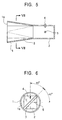
- FIG. 5 is a structural view of a primary radiator according to a second embodiment of the present invention
- FIG. 6 is a left side view of the primary radiator
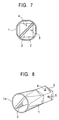
- FIG. 7 is a sectional view taken along line VII-VII in FIG. 5
- FIG. 8 is a perspective view of the primary radiator.
- the dielectric plate 3 is placed inside the first waveguide 1 having the circular opening 1a, and is disposed at an angle of approximately 45° with respect to the flat surfaces of the second waveguide 2 connected to the first waveguide 1, even when the length of the dielectric plate 3 is reduced, the phase difference with respect to orthogonal polarized waves is increased, and the size of the primary radiator can be reduced. Furthermore, since the corners between the adjoining inner wall surfaces of the second waveguide 2 are set to be inscribed in the opening 1a of the first waveguide 1, the first waveguide 1 and the second waveguide 2 connected in the axial direction can be easily produced by, for example, extending a part of a rectangular waveguide having the same cross section as that of the second waveguide 2 by rolling.
Landscapes
- Waveguide Switches, Polarizers, And Phase Shifters (AREA)
- Waveguide Aerials (AREA)
- Non-Reversible Transmitting Devices (AREA)
Abstract
Description
Claims (4)
- A primary radiator comprising:wherein said inner wall surface of said second waveguide is disposed at an angle of approximately 45° with respect to said dielectric plate.a first waveguide having a rectangular opening at one end;a dielectric plate placed inside said first waveguide so as to be substantially orthogonal to two parallel sides of said opening;a second waveguide of rectangular cross section coaxially connected to the other end of said first waveguide; anda probe protruding from an inner wall surface of said second waveguide toward the center axis,
- A primary radiator comprising:wherein said inner wall surface of said second waveguide is disposed at an angle of approximately 45° with respect to said dielectric plate.a first waveguide having a circular opening at one end;a dielectric plate placed inside said first waveguide;a second waveguide of rectangular cross section coaxially connected to the other end of said first waveguide; anda probe protruding from an inner wall surface of said second waveguide toward the center axis,
- A primary radiator according to Claim 1, wherein a corner between adjoining inner wall surfaces of said second waveguide is disposed so as to be inscribed in said opening.
- A primary radiator according to Claim 2, wherein a corner between adjoining inner wall surfaces of said second waveguide is disposed so as to be inscribed in said opening.
Applications Claiming Priority (2)
| Application Number | Priority Date | Filing Date | Title |
|---|---|---|---|
| JP2000227473A JP3739637B2 (en) | 2000-07-27 | 2000-07-27 | Primary radiator |
| JP2000227473 | 2000-07-27 |
Publications (3)
| Publication Number | Publication Date |
|---|---|
| EP1176666A2 true EP1176666A2 (en) | 2002-01-30 |
| EP1176666A3 EP1176666A3 (en) | 2002-06-26 |
| EP1176666B1 EP1176666B1 (en) | 2003-10-22 |
Family
ID=18720917
Family Applications (1)
| Application Number | Title | Priority Date | Filing Date |
|---|---|---|---|
| EP01306332A Expired - Lifetime EP1176666B1 (en) | 2000-07-27 | 2001-07-24 | Primary radiator having a shorter dielectric plate |
Country Status (4)
| Country | Link |
|---|---|
| US (1) | US6437754B2 (en) |
| EP (1) | EP1176666B1 (en) |
| JP (1) | JP3739637B2 (en) |
| DE (1) | DE60101025D1 (en) |
Cited By (2)
| Publication number | Priority date | Publication date | Assignee | Title |
|---|---|---|---|---|
| US7864104B2 (en) | 2005-05-11 | 2011-01-04 | Endress + Hauser Gmbh + Co. Kg | Device for determining and monitoring the level of a medium in a container |
| CN103022680A (en) * | 2012-12-21 | 2013-04-03 | 东南大学 | Phase-calibrated 3D-package surface antenna with embedded plated through holes |
Families Citing this family (7)
| Publication number | Priority date | Publication date | Assignee | Title |
|---|---|---|---|---|
| JP2002252519A (en) * | 2001-02-26 | 2002-09-06 | Alps Electric Co Ltd | Primary radiator |
| US6995726B1 (en) * | 2004-07-15 | 2006-02-07 | Rockwell Collins | Split waveguide phased array antenna with integrated bias assembly |
| JP4252096B2 (en) * | 2007-02-28 | 2009-04-08 | シャープ株式会社 | Orthogonal dual polarization waveguide input device, radio wave receiving converter and antenna device using the same |
| KR101140329B1 (en) | 2010-02-24 | 2012-05-03 | 연세대학교 산학협력단 | Excitation probe protecting apparatus and horn antenna comprising it |
| EP2664029B1 (en) * | 2011-01-12 | 2022-03-09 | Lockheed Martin Corporation | Printed circuit board based feed horn |
| DE102016014385A1 (en) * | 2016-12-02 | 2018-06-07 | Kathrein-Werke Kg | Dual polarized horn |
| FR3105884B1 (en) * | 2019-12-26 | 2021-12-03 | Thales Sa | Circular polarization dual band Ka satellite antenna horn |
Family Cites Families (11)
| Publication number | Priority date | Publication date | Assignee | Title |
|---|---|---|---|---|
| US3388399A (en) * | 1965-03-25 | 1968-06-11 | Navy Usa | Antenna feed for two coordinate tracking radars |
| US4041499A (en) * | 1975-11-07 | 1977-08-09 | Texas Instruments Incorporated | Coaxial waveguide antenna |
| US4065772A (en) * | 1976-07-06 | 1977-12-27 | Adams-Russell Co., Inc. | Broadbeam radiation of circularly polarized energy |
| FR2506082A1 (en) * | 1981-05-15 | 1982-11-19 | Thomson Csf | CIRCULARLY POLARIZED ELECTROMAGNETIC WAVE RADIATOR |
| GB8501440D0 (en) * | 1985-01-21 | 1985-02-20 | Era Patents Ltd | Circularly polorizing antenna feed |
| JPH0754759B2 (en) * | 1987-04-27 | 1995-06-07 | 日本電信電話株式会社 | Plasma processing method and apparatus, and mode converter for plasma processing apparatus |
| JPH0174613U (en) * | 1987-07-06 | 1989-05-19 | ||
| GB8816276D0 (en) * | 1988-07-08 | 1988-08-10 | Marconi Co Ltd | Waveguide coupler |
| US4885556A (en) * | 1988-11-01 | 1989-12-05 | The Boeing Company | Circularly polarized evanescent mode radiator |
| DE4322992A1 (en) * | 1993-07-09 | 1995-01-19 | Hirschmann Richard Gmbh Co | Transmission and/or reception system with optimised polarisation conversion |
| US5459441A (en) * | 1994-01-13 | 1995-10-17 | Chaparral Communications Inc. | Signal propagation using high performance dual probe |
-
2000
- 2000-07-27 JP JP2000227473A patent/JP3739637B2/en not_active Expired - Fee Related
-
2001
- 2001-07-24 EP EP01306332A patent/EP1176666B1/en not_active Expired - Lifetime
- 2001-07-24 DE DE60101025T patent/DE60101025D1/en not_active Expired - Lifetime
- 2001-07-26 US US09/915,581 patent/US6437754B2/en not_active Expired - Fee Related
Cited By (3)
| Publication number | Priority date | Publication date | Assignee | Title |
|---|---|---|---|---|
| US7864104B2 (en) | 2005-05-11 | 2011-01-04 | Endress + Hauser Gmbh + Co. Kg | Device for determining and monitoring the level of a medium in a container |
| CN103022680A (en) * | 2012-12-21 | 2013-04-03 | 东南大学 | Phase-calibrated 3D-package surface antenna with embedded plated through holes |
| CN103022680B (en) * | 2012-12-21 | 2015-05-06 | 东南大学 | Phase-calibrated 3D-package surface antenna with embedded plated through holes |
Also Published As
| Publication number | Publication date |
|---|---|
| EP1176666B1 (en) | 2003-10-22 |
| JP2002043830A (en) | 2002-02-08 |
| US6437754B2 (en) | 2002-08-20 |
| EP1176666A3 (en) | 2002-06-26 |
| JP3739637B2 (en) | 2006-01-25 |
| DE60101025D1 (en) | 2003-11-27 |
| US20020011964A1 (en) | 2002-01-31 |
Similar Documents
| Publication | Publication Date | Title |
|---|---|---|
| CA1179753A (en) | Microwave receiver for circularly polarized signals | |
| EP0871239B1 (en) | Antenna device and radar module | |
| EP1782500B1 (en) | Wave-guide-notch antenna | |
| CA1130875A (en) | Rotatable polarization duplexer | |
| EP3635811B1 (en) | Microwave circular polarizer | |
| EP0817394A2 (en) | Transmitter-receiver | |
| JP3706522B2 (en) | Waveguide device for satellite receiving converter | |
| JP4111237B2 (en) | Waveguide corner and radio equipment | |
| US6437754B2 (en) | Primary radiator having a shorter dielectric plate | |
| US6529089B2 (en) | Circularly polarized wave generator using a dielectric plate as a 90° phase shifter | |
| KR101215168B1 (en) | Orthomode transducer using trapezoidal waveguide | |
| US4366453A (en) | Orthogonal mode transducer having interface plates at the junction of the waveguides | |
| US6377224B2 (en) | Dual band microwave radiating element | |
| US4458217A (en) | Slot-coupled microwave diplexer and coupler therefor | |
| US6624715B2 (en) | Ultrawide-band linear-circular polarization converter | |
| US6677910B2 (en) | Compact primary radiator | |
| US4476470A (en) | Three horn E-plane monopulse feed | |
| JPS6014501A (en) | Polarization coupler | |
| JPH05235603A (en) | Horizontal and vertical polarization switching feed horn | |
| JP4103330B2 (en) | NRD guide L type antenna element | |
| JPH03190402A (en) | Circularly polarized wave/linearly polarized wave converter | |
| JPH01151803A (en) | Circular-linear polarized wave converter | |
| JPH0758503A (en) | Circularly polarized feed horn | |
| JP3805948B2 (en) | Primary radiator | |
| JP3646443B2 (en) | Mode converter, multiplexer / demultiplexer, mixer, and swirling polarization radiator |
Legal Events
| Date | Code | Title | Description |
|---|---|---|---|
| PUAI | Public reference made under article 153(3) epc to a published international application that has entered the european phase |
Free format text: ORIGINAL CODE: 0009012 |
|
| AK | Designated contracting states |
Kind code of ref document: A2 Designated state(s): AT BE CH CY DE DK ES FI FR GB GR IE IT LI LU MC NL PT SE TR |
|
| AX | Request for extension of the european patent |
Free format text: AL;LT;LV;MK;RO;SI |
|
| PUAL | Search report despatched |
Free format text: ORIGINAL CODE: 0009013 |
|
| AK | Designated contracting states |
Kind code of ref document: A3 Designated state(s): AT BE CH CY DE DK ES FI FR GB GR IE IT LI LU MC NL PT SE TR |
|
| AX | Request for extension of the european patent |
Free format text: AL;LT;LV;MK;RO;SI |
|
| RIC1 | Information provided on ipc code assigned before grant |
Free format text: 7H 01Q 13/00 A, 7H 01P 1/165 B, 7H 01Q 13/02 B |
|
| 17P | Request for examination filed |
Effective date: 20020701 |
|
| 17Q | First examination report despatched |
Effective date: 20020920 |
|
| AKX | Designation fees paid |
Designated state(s): DE FR GB |
|
| GRAH | Despatch of communication of intention to grant a patent |
Free format text: ORIGINAL CODE: EPIDOS IGRA |
|
| GRAS | Grant fee paid |
Free format text: ORIGINAL CODE: EPIDOSNIGR3 |
|
| GRAA | (expected) grant |
Free format text: ORIGINAL CODE: 0009210 |
|
| AK | Designated contracting states |
Kind code of ref document: B1 Designated state(s): DE FR GB |
|
| PG25 | Lapsed in a contracting state [announced via postgrant information from national office to epo] |
Ref country code: FR Free format text: LAPSE BECAUSE OF FAILURE TO SUBMIT A TRANSLATION OF THE DESCRIPTION OR TO PAY THE FEE WITHIN THE PRESCRIBED TIME-LIMIT Effective date: 20031022 |
|
| REG | Reference to a national code |
Ref country code: GB Ref legal event code: FG4D |
|
| REG | Reference to a national code |
Ref country code: IE Ref legal event code: FG4D |
|
| REF | Corresponds to: |
Ref document number: 60101025 Country of ref document: DE Date of ref document: 20031127 Kind code of ref document: P |
|
| PG25 | Lapsed in a contracting state [announced via postgrant information from national office to epo] |
Ref country code: DE Free format text: LAPSE BECAUSE OF FAILURE TO SUBMIT A TRANSLATION OF THE DESCRIPTION OR TO PAY THE FEE WITHIN THE PRESCRIBED TIME-LIMIT Effective date: 20040123 |
|
| PLBE | No opposition filed within time limit |
Free format text: ORIGINAL CODE: 0009261 |
|
| STAA | Information on the status of an ep patent application or granted ep patent |
Free format text: STATUS: NO OPPOSITION FILED WITHIN TIME LIMIT |
|
| 26N | No opposition filed |
Effective date: 20040723 |
|
| EN | Fr: translation not filed | ||
| REG | Reference to a national code |
Ref country code: IE Ref legal event code: MM4A |
|
| PGFP | Annual fee paid to national office [announced via postgrant information from national office to epo] |
Ref country code: GB Payment date: 20050617 Year of fee payment: 5 |
|
| PG25 | Lapsed in a contracting state [announced via postgrant information from national office to epo] |
Ref country code: GB Free format text: LAPSE BECAUSE OF NON-PAYMENT OF DUE FEES Effective date: 20060724 |
|
| GBPC | Gb: european patent ceased through non-payment of renewal fee |
Effective date: 20060724 |