EP1176663A1 - Téléphone multibande à antenne adaptée - Google Patents
Téléphone multibande à antenne adaptée Download PDFInfo
- Publication number
- EP1176663A1 EP1176663A1 EP01401926A EP01401926A EP1176663A1 EP 1176663 A1 EP1176663 A1 EP 1176663A1 EP 01401926 A EP01401926 A EP 01401926A EP 01401926 A EP01401926 A EP 01401926A EP 1176663 A1 EP1176663 A1 EP 1176663A1
- Authority
- EP
- European Patent Office
- Prior art keywords
- band
- telephone
- telephone according
- adaptation
- mobile telephone
- Prior art date
- Legal status (The legal status is an assumption and is not a legal conclusion. Google has not performed a legal analysis and makes no representation as to the accuracy of the status listed.)
- Withdrawn
Links
- 230000006978 adaptation Effects 0.000 claims description 17
- 230000005855 radiation Effects 0.000 claims description 16
- 239000003990 capacitor Substances 0.000 description 3
- 230000009977 dual effect Effects 0.000 description 3
- 239000004020 conductor Substances 0.000 description 2
- 230000005540 biological transmission Effects 0.000 description 1
- 239000000470 constituent Substances 0.000 description 1
- 230000000694 effects Effects 0.000 description 1
- 230000035939 shock Effects 0.000 description 1
Images

Classifications
-
- H—ELECTRICITY
- H01—ELECTRIC ELEMENTS
- H01Q—ANTENNAS, i.e. RADIO AERIALS
- H01Q9/00—Electrically-short antennas having dimensions not more than twice the operating wavelength and consisting of conductive active radiating elements
- H01Q9/04—Resonant antennas
- H01Q9/06—Details
- H01Q9/14—Length of element or elements adjustable
-
- H—ELECTRICITY
- H01—ELECTRIC ELEMENTS
- H01Q—ANTENNAS, i.e. RADIO AERIALS
- H01Q1/00—Details of, or arrangements associated with, antennas
- H01Q1/12—Supports; Mounting means
- H01Q1/22—Supports; Mounting means by structural association with other equipment or articles
- H01Q1/24—Supports; Mounting means by structural association with other equipment or articles with receiving set
- H01Q1/241—Supports; Mounting means by structural association with other equipment or articles with receiving set used in mobile communications, e.g. GSM
- H01Q1/242—Supports; Mounting means by structural association with other equipment or articles with receiving set used in mobile communications, e.g. GSM specially adapted for hand-held use
- H01Q1/243—Supports; Mounting means by structural association with other equipment or articles with receiving set used in mobile communications, e.g. GSM specially adapted for hand-held use with built-in antennas
-
- H—ELECTRICITY
- H01—ELECTRIC ELEMENTS
- H01Q—ANTENNAS, i.e. RADIO AERIALS
- H01Q1/00—Details of, or arrangements associated with, antennas
- H01Q1/36—Structural form of radiating elements, e.g. cone, spiral, umbrella; Particular materials used therewith
- H01Q1/362—Structural form of radiating elements, e.g. cone, spiral, umbrella; Particular materials used therewith for broadside radiating helical antennas
-
- H—ELECTRICITY
- H01—ELECTRIC ELEMENTS
- H01Q—ANTENNAS, i.e. RADIO AERIALS
- H01Q5/00—Arrangements for simultaneous operation of antennas on two or more different wavebands, e.g. dual-band or multi-band arrangements
- H01Q5/30—Arrangements for providing operation on different wavebands
- H01Q5/307—Individual or coupled radiating elements, each element being fed in an unspecified way
- H01Q5/314—Individual or coupled radiating elements, each element being fed in an unspecified way using frequency dependent circuits or components, e.g. trap circuits or capacitors
- H01Q5/328—Individual or coupled radiating elements, each element being fed in an unspecified way using frequency dependent circuits or components, e.g. trap circuits or capacitors between a radiating element and ground
Definitions
- the present invention relates to a mobile telephone with antenna adapted. It therefore applies to the field of mobile telephony and more especially multiband mobile phones.
- a phone multiband is a telephone that can operate in several bands of frequencies, at least two, a frequency band grouping a sub band for transmission and a sub-band for reception. So we know the bands known as GSM, DCS, PCS or even UMTS for the best known.
- the object of the invention is to provide an at least dual band telephone with a radiation device suitable for at least two frequency bands.
- the object of the invention is to solve these problems by proposing a mobile phone with a radiation device adapted to it the first strip but also with respect to the second strip. So a value of the Standing Wave Rate or TOS is higher than previously which increases a power value radiated while having a very compact antenna.
- the principle can be extended to several frequencies, three or four for example or even more.
- the characteristics of the radiation device are modified according to a selected frequency band.
- a first end of the radiation device receives an input signal output from a transmitter mobile phone receiver, a second end being controlled by an adaptation means according to the invention intended to adapt the device radiation to the first band or to the second band as the case may be.
- the invention therefore relates to a multiband mobile telephone.
- a radiation device with a first and a second end, the first end being connected to an input output of a radio signal transmitter and receiver, characterized in that it includes an adaptation means cooperating with the radiation in order to adapt it to one of several bands.
- FIG. 1 shows a representation showing a principle of general operation of a mobile telephone 1 according to the invention.
- This phone 1 is a multiband phone. That is, the phone 1 can operate in a first band or a second band.
- a band is generally associated with a telephone system according to a certain standard.
- telephone 1 is a dual band telephone.
- the telephone 1 thus comprises, in this first case, a radiation device 2 with a first end 3 and a second end 4_1.
- the ends 3 and 4_1 correspond more precisely to two free ends of the device 2.
- This device 2 makes it possible to transmit and or to receive a radio signal 5 to and from respectively a base station 6 of a mobile telephone network 7.
- the end 3 is connected to an input output 8 of the transmitter telephone receiver 9 9.
- the function of transmitter 9 is to transmit and receive radio signals such as signal 5.
- the end 4_1 comprises an adaptation means 10_1 cooperating with the device 2. This cooperation results in an adaptation of device 2 to the first band or the second band depending on the frequency band in which the phone 1 should work.
- the means 10_1 makes it possible to adapt the device 2 to a particular frequency band.
- the second strip uses frequencies of the order of twice the value used by the first strip.
- the principle used by the invention can be understood using the theory called line theory.
- This line theory generally applies from the moment the length of the conductors used is of the order of magnitude of the wavelength of the through signal this conductor, or at least when the wavelength can no longer be considered to be much greater than the length of the line section considered.
- a section of line of the type known as quarter-wave line denomination, relative to a signal with a length reference wave behaves like a half-wave line, by relative to this reference wavelength, when its end, normally in open circuit, is short-circuited with respect to a plane of mass.
- a suitable antenna is normally a half-wave antenna but when the antenna is used in combination with a plane reflector such as a ground plane then a quarter-wave antenna can be used.
- the radiation device is of the quarter line type. wave with respect to an average frequency of the first band.
- the first frequency band is a band according to the GSM standard.
- a typical frequency of this GSM band is the frequency of 900 MHz.
- a double of this frequency, i.e. 1800 MHz, corresponds to a typical frequency value of the frequency band according to DCS standard which therefore corresponds to the second strip.
- a length waveform of the first band is around 33.3 cm is for the second band a wavelength of about 16.6 cm.
- the wavelength varies from 31.25 cm to 34.09 cm which gives a length wavelength of 32.67 cm and in the DCS band the wavelength varies from 15.9 cm to 17.54 cm which gives an average wavelength of 16.72 cm.
- These two average values are of the order of the proposed values of 33.3 cm and 16.6 cm and in addition the value of 32.67 cm is appreciably equal to double the value of 16.72 cm.
- the device 2 is produced with respect to the GSM band.
- the latter has a length equal to a quarter of the wavelength of the signal to transmit and / or receive such as signal 5, this in the case where the device 2 is used with respect to a ground plane which is the case here with plane 12.
- a physical length of device 2 is therefore of the order of 8.3 cm. Consequently, the device 2 as produced and not short-circuited at its end 4_1 is perfectly suited for transmitting signals or receive in the GSM band.
- the means 10_1 when the telephone 1 is to operate in the second frequency band, the DCS band, the means 10_1 must therefore be commanded to short-circuit the end 4_1 relative to the ground plane 12. It follows that the device 2 then behaves like an element half wave with respect to the reference wavelength in the band DCS.
- the frequency of signal 5 has now doubled which has the effect of dividing the wavelength by two. Consequently, the device 2 which behaves like a quarter-wave device compared to the GSM band then behaves like a half wave device compared to the DCS band. Thus, the device 2 is now adapted to transmit and or receive signals such as signal 5 in the DCS band. That is why in the case of such a dual-band telephone, the means 10_1 cooperates with the device 2 for adapting the latter by making a simple short circuit.
- FIG. 2 shows a first preferred embodiment of the medium 10_1.
- the switch 11_1 is a diode 13 of PIN type with an anode 14 and a cathode 15.
- Anode 14 is connected to the end 4_1 and the cathode 15 is connected to the ground plane 12.
- the anode 14 is connected to a switching device 16 or switch 16.
- This switch 16 has a first input 17 receiving a voltage positive, for example a supply voltage such as the voltage mobile phone supply 1.
- the device 16 further comprises a second input 18 connected to the ground plane 12 thus making it possible to produce a voltage of 0 Volt.
- the end 4_1 is connected to an outlet 19 of the device 16.
- a switching command for this switch 16 is provided by a microprocessor 20 controlled by a program 21 in a program memory 22.
- This microprocessor 20 is for example the microprocessor which manages an operation of the telephone 1 and therefore of the transceiver 9.
- the telephone 1 comprises a bus 23 of data, addresses and commands allowing the different elements to constituent of being linked together to communicate.
- the anode 14 of the diode 13 is connected to the output 19 by through a low pass filter 24 in series with a resistor 25 of protection.
- the filter 24 makes it possible in particular to avoid that signals with high frequency is not transmitted from device 2 to the power supply, thus parasitize the other circuits of the telephone 1.
- the filter 24 has a coil 26 or shock inductor 26 and a capacitor 27.
- the filter 24 thus has an inlet 28 and an outlet 29, the outlet 29 being connected to the anode 14 and the output 28 to a terminal of the resistor 25.
- the coil 26 is connected between input 28 and output 29 and capacitor 27 is connected between input 28 and ground plane 12.
- others realizations of filter 24 are possible the goal being to filter the components at high frequencies from the transceiver 9 in particular.
- the switch 16 is a controlled device electrically for example a signal having two logic states 1 or 0.
- Logical value 1 represents for example the positive voltage is the value logic 0 the voltage of 0 Volt.
- the microprocessor 20 emits a command at 1 at switch 16 which then switches to input 17. This has as a consequence of connecting input 17 to output 19. This gives, in output 19, a positive voltage which will therefore bias the diode 13 directly and therefore to make it conductive.
- the end 4_1 is then short-circuited by being electrically connected to the ground plane 12. This corresponds to an operating mode according to the DCS standard, i.e. that phone 1 transmits in the 1800 MHz band.
- the device 2 is adapted with respect to the wavelength of this DCS band.
- the microprocessor 20 sends in in this case a control signal to the device 16 whose logic value is 0.
- the output 19 is connected to the input 18.
- the device 2 is then used in the conditions for which it was made, i.e. as a device quarter wave relative to the reference wavelength.
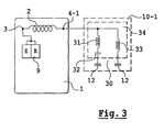
- Figure 3 shows a second embodiment of the means 10_1 adaptation of the radiation device 2.
- the means 10_1 comprises a filter 30 having an impedance infinite, or at least very strong, in the first band, i.e. in the GSM band and zero, or at least very low, impedance in the second band, ie the DCS band.
- this filter 30 must have two resonant frequencies, a series resonant frequency having resulting in zero impedance and a resonant frequency parallel resulting in infinite impedance. This can be easily obtained using passive component.
- This assembly forms a dipole 34, one of which end is connected to end 4_1 and the other end is connected to the plane of mass 12.
- This realization corresponds to a less effective realization than that preferred in FIG. 2 with the PIN diode because it is less wide band. Indeed, it is preferable to ensure an infinite impedance throughout the first GSM band and zero impedance in the entire second band DCS.
- the filter 30 therefore replaces the diode 13 to ensure the function light switch.
- Other embodiments for making the filter 30 can be envisaged and in particular realizations based on high resonator quality coefficient.
- the device 2 is an antenna helical integrated in phone 1, that is to say that it does not have no outgrowth as is usually the case.
- An antenna according to the invention a helical antenna is in the form of a solenoid. It can also be a printed circuit on which is engraved a conductive track most often in a lace form. This antenna 2 thus makes it possible to reduce a bulk due to the latter because normally the antenna should occupy an area whose length would be one quarter wavelength compared to the GSM band which corresponds to about 8.3 cm.
- phone 1 is multiband and can therefore operate in frequency bands B1 to Bn with n> 2.
- the antenna 2 also comprises the end 4_1 associated with the strip B1 of the second ends 4_2 to 4_n each being placed at a certain distance from end 3. Each distance is of the order of a quarter of the average wavelength of the frequency band B2 to Bn considered.
- These second ends 4_2 to 4_n each comprising a means 10_2 to 10_n of adaptation respectively.
- Each means 10_1 to 10_n cooperates with antenna 2 to ensure the adaptation of the latter with one of the frequency band B1 to Bn respectively.
- the means 10_2 to 10_n are produced in the same way as 10_1.
- the means 10_2 to 10_n therefore include a switch 11_2 to 11_n respectively. These switches 11_2 to 11_n are made so same as switch 11_1.
- each filter can also be produced using a filter such as filter 30.
- Each filter then has a zero impedance only for the frequency band with which it is associated and infinite in the other cases or at least large enough to be able to consider it as such.
- each means 10_1 to 10_n is provided with an impedance 35_1 to 35_n respectively of fine adjustment locally improving the quality of the antenna 2 adaptation to one of the bands B1 to Bn.
Landscapes
- Engineering & Computer Science (AREA)
- Computer Networks & Wireless Communication (AREA)
- Transceivers (AREA)
Abstract
Description
- Figure 1 : un principe de fonctionnement général du moyen d'adaptation selon l'invention.
- Figure 2 : un premier exemple de réalisation du moyen d'adaptation selon l'invention.
- Figure 3 : un deuxième exemple de réalisation du moyen d'adaptation selon l'invention.
Claims (8)
- Téléphone (1) mobile multibande comportant un dispositif (2) de rayonnement avec deux extrémités, une première (3) et une deuxième extrémité (4_1 - 4_n), la première extrémité (3) étant reliée à une entrée sortie (8) d'un émetteur récepteur (9) d'un signal (5) radioélectrique, caractérisé en ce qu'il comporte un moyen interrupteur (11_1 - 11_n) permettant de court-circuiter ou non la deuxième extrémité (4_1 - 4_n) à la masse.
- Téléphone selon la revendication 1 caractérisé en ce que le moyen interrupteur comporte un moyen d'adaptation coopérant avec le dispositif de rayonnement afin d'adapter ce dernier à une bande parmi plusieurs.
- Téléphone selon la revendication 2, caractérisé en ce qu'une deuxième bande utilise des fréquences de l'ordre du double de celles utilisées dans une première bande.
- Téléphone selon la revendication 3, caractérisé en ce que le moyen interrupteur comporte un filtre (30) présentant une impédance très forte dans la première bande et une impédance très faible dans la deuxième bande.
- Téléphone selon l'une des revendications 1 à 4, caractérisé en ce que le moyen interrupteur est muni d'une impédance (35_1 à 35_n) de réglage fin.
- Téléphone selon l'une des revendications 1 à 5, caractérisé en ce qu'il comporte un jeu de deuxièmes extrémités chacune comportant un moyen d'adaptation.
- Téléphone selon l'une des revendications 1 à 6, caractérisé en ce que le moyen interrupteur comporte une diode (13) PIN dont la cathode (15) est reliée à la masse (12) et l'anode (14) à la deuxième extrémité, la diode PIN étant en outre reliée à un circuit (16) de commutation assurant sa conduction ou non.
- Téléphone selon l'une des revendications 1 à 7, caractérisé en ce que le dispositif de rayonnement est une antenne hélicoïdale intégrée dans le téléphone.
Applications Claiming Priority (2)
| Application Number | Priority Date | Filing Date | Title |
|---|---|---|---|
| FR0010013A FR2812511B1 (fr) | 2000-07-28 | 2000-07-28 | Telephone multibande a antenne adaptee |
| FR0010013 | 2000-07-28 |
Publications (1)
| Publication Number | Publication Date |
|---|---|
| EP1176663A1 true EP1176663A1 (fr) | 2002-01-30 |
Family
ID=8853092
Family Applications (1)
| Application Number | Title | Priority Date | Filing Date |
|---|---|---|---|
| EP01401926A Withdrawn EP1176663A1 (fr) | 2000-07-28 | 2001-07-18 | Téléphone multibande à antenne adaptée |
Country Status (2)
| Country | Link |
|---|---|
| EP (1) | EP1176663A1 (fr) |
| FR (1) | FR2812511B1 (fr) |
Cited By (1)
| Publication number | Priority date | Publication date | Assignee | Title |
|---|---|---|---|---|
| US7403173B2 (en) | 2005-12-22 | 2008-07-22 | Samsung Electronics Co., Ltd. | Antenna device |
Citations (5)
| Publication number | Priority date | Publication date | Assignee | Title |
|---|---|---|---|---|
| US4554554A (en) * | 1983-09-02 | 1985-11-19 | The United States Of America As Represented By The Secretary Of The Navy | Quadrifilar helix antenna tuning using pin diodes |
| US4564843A (en) * | 1981-06-18 | 1986-01-14 | Cooper Charles E | Antenna with P.I.N. diode switched tuning inductors |
| US4656483A (en) * | 1983-09-28 | 1987-04-07 | Avions Marcel Dassault-Breguet Aviation | Switchable antenna for the VHF and UHF frequency bands |
| US5521607A (en) * | 1993-08-10 | 1996-05-28 | Rockwell International | Bandswitched electrically short tactical monopole antenna system |
| US6011964A (en) * | 1996-08-30 | 2000-01-04 | Nec Corporation | Helical antenna for a portable radio apparatus |
-
2000
- 2000-07-28 FR FR0010013A patent/FR2812511B1/fr not_active Expired - Fee Related
-
2001
- 2001-07-18 EP EP01401926A patent/EP1176663A1/fr not_active Withdrawn
Patent Citations (5)
| Publication number | Priority date | Publication date | Assignee | Title |
|---|---|---|---|---|
| US4564843A (en) * | 1981-06-18 | 1986-01-14 | Cooper Charles E | Antenna with P.I.N. diode switched tuning inductors |
| US4554554A (en) * | 1983-09-02 | 1985-11-19 | The United States Of America As Represented By The Secretary Of The Navy | Quadrifilar helix antenna tuning using pin diodes |
| US4656483A (en) * | 1983-09-28 | 1987-04-07 | Avions Marcel Dassault-Breguet Aviation | Switchable antenna for the VHF and UHF frequency bands |
| US5521607A (en) * | 1993-08-10 | 1996-05-28 | Rockwell International | Bandswitched electrically short tactical monopole antenna system |
| US6011964A (en) * | 1996-08-30 | 2000-01-04 | Nec Corporation | Helical antenna for a portable radio apparatus |
Cited By (1)
| Publication number | Priority date | Publication date | Assignee | Title |
|---|---|---|---|---|
| US7403173B2 (en) | 2005-12-22 | 2008-07-22 | Samsung Electronics Co., Ltd. | Antenna device |
Also Published As
| Publication number | Publication date |
|---|---|
| FR2812511B1 (fr) | 2003-04-11 |
| FR2812511A1 (fr) | 2002-02-01 |
Similar Documents
| Publication | Publication Date | Title |
|---|---|---|
| EP1374340B1 (fr) | Antenne commutee | |
| FR2822301A1 (fr) | Antenne a bande elargie pour appareils mobiles | |
| EP1172929B1 (fr) | Dispositif d'amplification à faible bruit, en particulier pour un téléphone mobile cellulaire | |
| EP1427053A1 (fr) | Coupleur directif | |
| EP0604338A1 (fr) | Antenne large bande à encombrement réduit, et dispositf d'émission/réception correspondant | |
| FR2817661A1 (fr) | Dispositif pour la reception et/ou l'emission de signaux multifaisceaux | |
| EP3017499A1 (fr) | Filtre rejecteur de bande | |
| EP3352301B1 (fr) | Antenne pour dispositif mobile de communication | |
| EP2178152A1 (fr) | Dispositif de commutation électronique pour signaux a haute fréquence | |
| EP1176663A1 (fr) | Téléphone multibande à antenne adaptée | |
| WO2005125034A1 (fr) | Dispositif rayonnant comprenant au moins un filtre rejecteur adaptatif et antenne comprenant ce dispositif | |
| EP1283599A1 (fr) | Système d'émission/réception pour téléphone mobile multibande et multimode | |
| FR2967537A1 (fr) | Antenne compacte adaptable en impedance | |
| FR2664447A1 (fr) | Dispositif de couplage d'une antenne a des organes de radio communication. | |
| EP0578561B1 (fr) | Récepteur du type à antenne intérieure en ferrite | |
| FR2622054A1 (fr) | Cavite a accord commutable pour filtre passe-bande, notamment pour duplexeur, et emetteur-recepteur pour radiotelephonie comprenant une telle cavite | |
| FR3073995A1 (fr) | Systeme d'au moins deux unites emettrices et/ou receptrices reliees a une antenne commune | |
| EP1538696A1 (fr) | Téléphone mobile bi-bande à diagramme de rayonnement omnidirectionnel | |
| EP1956682B1 (fr) | Antenne monopôle à commutation | |
| EP1548877B1 (fr) | Antenne à surface(s) rayonnante(s) plane(s) multibande et téléphone portable comportant une telle antenne | |
| EP1715597B1 (fr) | Antenne à surfaces rayonnantes planes à circuit commutable | |
| FR2828626A1 (fr) | Systeme d'emission/reception pour telephone mobile multibande et multimode | |
| FR2816114A1 (fr) | Antenne multibande | |
| FR2868215A1 (fr) | Systeme et procede de commande dynamique de la largeur de la bande passante d'une antenne, telephone associe | |
| FR2878680A1 (fr) | Terminal de communication mobile |
Legal Events
| Date | Code | Title | Description |
|---|---|---|---|
| PUAI | Public reference made under article 153(3) epc to a published international application that has entered the european phase |
Free format text: ORIGINAL CODE: 0009012 |
|
| AK | Designated contracting states |
Kind code of ref document: A1 Designated state(s): DE ES GB IT Kind code of ref document: A1 Designated state(s): AT BE CH CY DE DK ES FI FR GB GR IE IT LI LU MC NL PT SE TR |
|
| AX | Request for extension of the european patent |
Free format text: AL;LT;LV;MK;RO;SI |
|
| 17P | Request for examination filed |
Effective date: 20020309 |
|
| 17Q | First examination report despatched |
Effective date: 20020802 |
|
| AKX | Designation fees paid |
Free format text: DE ES GB IT |
|
| STAA | Information on the status of an ep patent application or granted ep patent |
Free format text: STATUS: THE APPLICATION IS DEEMED TO BE WITHDRAWN |
|
| 18D | Application deemed to be withdrawn |
Effective date: 20030213 |