EP1176537A2 - Medical data processing method and medical data processing system - Google Patents
Medical data processing method and medical data processing system Download PDFInfo
- Publication number
- EP1176537A2 EP1176537A2 EP01117290A EP01117290A EP1176537A2 EP 1176537 A2 EP1176537 A2 EP 1176537A2 EP 01117290 A EP01117290 A EP 01117290A EP 01117290 A EP01117290 A EP 01117290A EP 1176537 A2 EP1176537 A2 EP 1176537A2
- Authority
- EP
- European Patent Office
- Prior art keywords
- image data
- data
- outputting
- type
- button
- Prior art date
- Legal status (The legal status is an assumption and is not a legal conclusion. Google has not performed a legal analysis and makes no representation as to the accuracy of the status listed.)
- Withdrawn
Links
Images



Classifications
-
- A—HUMAN NECESSITIES
- A61—MEDICAL OR VETERINARY SCIENCE; HYGIENE
- A61B—DIAGNOSIS; SURGERY; IDENTIFICATION
- A61B3/00—Apparatus for testing the eyes; Instruments for examining the eyes
- A61B3/0016—Operational features thereof
- A61B3/0041—Operational features thereof characterised by display arrangements
- A61B3/0058—Operational features thereof characterised by display arrangements for multiple images
-
- G—PHYSICS
- G16—INFORMATION AND COMMUNICATION TECHNOLOGY [ICT] SPECIALLY ADAPTED FOR SPECIFIC APPLICATION FIELDS
- G16H—HEALTHCARE INFORMATICS, i.e. INFORMATION AND COMMUNICATION TECHNOLOGY [ICT] SPECIALLY ADAPTED FOR THE HANDLING OR PROCESSING OF MEDICAL OR HEALTHCARE DATA
- G16H30/00—ICT specially adapted for the handling or processing of medical images
- G16H30/20—ICT specially adapted for the handling or processing of medical images for handling medical images, e.g. DICOM, HL7 or PACS
-
- G—PHYSICS
- G16—INFORMATION AND COMMUNICATION TECHNOLOGY [ICT] SPECIALLY ADAPTED FOR SPECIFIC APPLICATION FIELDS
- G16H—HEALTHCARE INFORMATICS, i.e. INFORMATION AND COMMUNICATION TECHNOLOGY [ICT] SPECIALLY ADAPTED FOR THE HANDLING OR PROCESSING OF MEDICAL OR HEALTHCARE DATA
- G16H40/00—ICT specially adapted for the management or administration of healthcare resources or facilities; ICT specially adapted for the management or operation of medical equipment or devices
- G16H40/60—ICT specially adapted for the management or administration of healthcare resources or facilities; ICT specially adapted for the management or operation of medical equipment or devices for the operation of medical equipment or devices
- G16H40/63—ICT specially adapted for the management or administration of healthcare resources or facilities; ICT specially adapted for the management or operation of medical equipment or devices for the operation of medical equipment or devices for local operation
-
- G—PHYSICS
- G16—INFORMATION AND COMMUNICATION TECHNOLOGY [ICT] SPECIALLY ADAPTED FOR SPECIFIC APPLICATION FIELDS
- G16Z—INFORMATION AND COMMUNICATION TECHNOLOGY [ICT] SPECIALLY ADAPTED FOR SPECIFIC APPLICATION FIELDS, NOT OTHERWISE PROVIDED FOR
- G16Z99/00—Subject matter not provided for in other main groups of this subclass
Definitions
- the invention relates to a medical data processing method and system for storing, managing and processing data, such as image data, obtained by a medical apparatus.
- Amedical data processing system is designed to store, manage and process image data and others, in the form of files, obtained by a medical apparatus such as a slit lamp microscrope (called as “slit lamp”) or a fundus camera by use of a personal computer (called as "PC").
- a medical apparatus such as a slit lamp microscrope (called as “slit lamp”) or a fundus camera by use of a personal computer (called as "PC”).
- a storage folder is previously prepared on a patient-by-patient base in PC.
- a storage folder for the patient (patient record) is designated each time so that the data is inputted to and stored in the storage folder in the PC.
- a suitable operation corresponding to the purpose of use with the data must be executed. For example, if the data is to be printed out on a paper, the data is selected and then a printing operation is carried out. If the data is to be sent to a remote PC (other PC), the data is stored in a floppy disk to be carried to the remote PC, or the data is attached to E-mail for transmission. These tasks require respective different operations, and thus troublesome.
- the invention is characterized by having the following arrangement.
- Fig. 1 shows a structure of a medical data processing system for storing managing and processing ophthalmic data, such as image data, measured data and others obtained by an ophthalmologic apparatus.
- Reference numeral 1 designates a PC, which includes, in the inside thereof, an arithmetic and control unit 2, an information recording and reproducing section (nonvolatile memory) 3 constructed by a hard disk drive, a RAM 4 (Random Access Memory), an input section 5, constructed by a video capture, for inputting image data to the PC1, and a communication section 40 for exchanging (communicating) data with another PC 1'.
- the recording and reproducing section 3, RAM 4, input section 5 and communication section 40 are connected to the arithmetic and control unit 2.
- a data processing software 10 (described later) is recorded (installed) in the inside of the recording and reproducing section 3, and when this software 10 is started up, the medical data processing system is ready for using.
- storage folders (folders 12a, 12b.7) are prepared on a patient-by-patient basis, and image data for each patient is stored in the respective folder. If image data is inputted without the designation of the patient, the image data is stored in a Queue folder 11. These operations will be described in detail later.
- the information recording and reproducing section 3 not only the hard disk drive but also DVD drive, a floppy disk drive, or the like may be used.
- the input section 5 is connected to a fundus camera 20 and a slit lamp 30.
- An imaging system such as CCD camera, a digital camera (not shown) or the like for capturing (obtaining) images is preliminarily provided to each of the fundus camera 20 and the slit lamp 30, so that image data obtained by each imaging system is inputted via the input section 5 into the PC 1.
- a communication section 40 is furnished with a modem and a LAN board, enabling mutual communications with other PCs 1' through an internet 41 or an LAN 42 (Local Area Network).
- Reference numeral 13 designates a printer for outputting the inputted image onto a paper.
- Reference numeral 15 designates a display for which a general purposed display, such as a LCD or CRT monitor, can be used.
- Reference numeral 16 designates an operation section for issuing operation instructions to the PC 1 or the started software 10. As the operation section 16, a key board 16a and a mouse 16b are used.
- the arithmetic and control unit 2 reads the software 10 from the recording and reproducing section 3 and causes it to be resident in RAM 4.
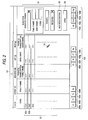
- the software 10 is mainly made up of four processing screens. The processing screens are respectively shown in Figs. 2 to 5, and each of them will be explained.
- a patient list screen is first displayed on the display 15 as viewed in Fig. 2.
- This screen serves as a main screen with which indication of a list of already registered patients, search for a patient, and receipt (registration) of a new patient, and the like can be executed.
- the list of registered patients is indicated in order as a patient 50a, a patient 50b .... in a display column 50.
- a respective storage folder For each of the registered patients, a respective storage folder has been prepared within the recording and reproducing section 3.
- a holder 12a for the patient 50a and a holder 12b for the patient 50b have been prepared, respectively.
- a vertical row (a column) is provided, which includes a button (icon) group 51 for searching a registered patient, a registration button (icon) 52 for new registration, and an open (disclosure) button (icon) 53 for retrieving details of individual patient data.
- a cursor mark 110 shown on the display 15 is moved onto a desired button (icon) with the mouse 16b, and then an unillustrated button on the mouse 16b is clicked.
- shortcut button (icon) group 100 is provided so that 12 pieces of shortcut buttons (icons) 100-a to 100-1 can be used. These shortcut buttons 100-a to 100-1 correspond respectively to tasks assigned to function keys (Fl to F12) of the key board 16a.
- shortcut keys To the function keys of the key board 16a, various functions (tasks), such as measurement, screen change, etc. are assigned as shortcut keys to enable these tasks with a single operation of the keyboard.
- the task assignment to the function keys may be set arbitrarily to match with user's convenience.
- the shortcut buttons (icons) provided in this embodiment include a button (icon) 100a for movement to the main screen, a button (icon) 100b for displaying the patient list, a button (icon) 100c for obtaining image data from the fundus camera 20, a button (icon) 100d for obtaining image data from the slit lamp 30, a button (icon) 100e for displaying, in a thumbnail fashion, all image data stored in the Queue folder 11, and a button (icons) 100f for outputting selected image data using the printer 13.
- no task is assigned to the remaining buttons (icons) 100-g to 100-1.
- a menu bar 54 is displayed, which contains items of "File”, “Patient”, “Measure”, “Set”, and “Help”, and main functions (such as switch of a displayed screen) may be selected and used via this menu bar 54.
- Fig. 3 shows a screen with which a new patient is registered, or registered patient data is displayed. Thisregistrationscreen can be displayed upon operation of the registration button 52 or the open button 53 shown in Fig. 2.
- buttons (icons) are displayed in a hierarchical structure view (tree view 84), which respectively identify collected medical data such as image data obtained till now and measured data, and their stored contents or conditions are visually grasped.
- a patient data registration screen 60 is used to register a new patient.
- Input items of the patient data are "Name”, “Phonetic transcription”, “Sex”, “Birthday”, “Code”, “Day of first medical examination”, “Address”, and "Tel. No.”.
- Reference numeral 61 designates an OK button (icon) for executing registration, and 62 is a cancel button (icon) for canceling registration.
- Fig. 4 shows an image input screen with which patient's eye image data obtained by the fundus camera or the slit lamp 30 is input into the PC 1.
- Reference numeral 70 designates a main image box, in which a latest inputted image is shown largely.
- 71 is a thumbnail indication box, in which the inputted images are displayed sequentially as thumbnail images 70a, 70b.
- thumbnail box 71 In case where a plurality of thumbnail images are displayed on the thumbnail box 71, the selection of one among these images will cause the selected thumbnail image to be displayed on the main image box 70 in an enlarged manner.
- Reference numeral 73 designates a set button (icon) group for setting data of eye examination with respect to the inputted image.
- set button group date of eye examination, designation of left or right eye, an image format, and an image capture mode can be selected and set.
- image format and the image capture mode several options (selection items) are preliminarily registered to form a pull-down menu (for example, in a case of the image format, JPEG image High quality, JPEG image Low quality, etc., and in a case of the fundus camera, color fundus image, FAG fundus image, ICG fundus image, etc.), and any of them is selected and set using the pull-down menu.
- the image of patient' s eye is inputted from the ophthalmologic apparatus (the fundus camera 20 or the slit lamp 30) by clicking an input button (icon) 74.
- the input operation for the image data may be carried out using a joystick or a foot switch (both not shown) provided in the ophthalmologic apparatus other than the use of the input button 74.
- Reference numeral 75 is a finish button (icon) for finishing the transfer operation, and returning to the latest previous operation screen.
- Fig. 5 shows an image storage screen in which the image data stored in the storage folder is displayed.
- a radio button 85 may be used to alter the hierarchical structure.
- a button (icon) for example, a fundus image button (icon) 84a
- the image data corresponding to the selected button (icon) is displayed as thumbnails 88a, 88b in the screen 80.
- buttons (icons) set in a date selection tool bar 81 for selecting a date of an image to be displayed, a kind selection tool bar 82 for selecting a kind of an image to be displayed, and a control tool bar 83 for designating a displaying condition such as a left or right eye, maybe selectively used to select a thumbnail image to be displayed on the display screen 80.
- Reference numeral 86 is an output button (icon) for outputting the thumbnail image displayed on the display screen 80 (for usage other than the image data to be used in the software 10). Beside the output button 86, a button (icon) 86a for a pulling down menu is provided, and by clicking the button 86a, the output type (form) may be set variously.
- Fig. 7 shows a pull-down menu 87 displayed using the button 86a.
- Items for output type of the image data include a mail sending item 87a for selecting and setting output type of the image file as an appending file to a general purposed mail software, a DICOM (Digital Imaging and Communications in Medicine) output item 87b for selecting and setting output type of the image data as a DICOM data to a My Document folder, a JPEG output item 87c for selecting and setting output type of the image data as JPEG data, which is one kind of image formats, to the My Document folder, an FP output item 87d for selecting and setting output type of the image data to a floppy disk in the JPEG data, a printer output item 87e for selecting and setting output type of the image data to the printer 13, and an account output item 87f for selecting and setting output type of the image data as a medical account.
- a mail sending item 87a for selecting and setting output type of the image file as an appending file to a general purposed mail
- the appearance of the output button 86 is changed to correspond to the selected output item. (In Fig. 7, the icon corresponding to the FP output item 87d is shown.)
- Fig. 6 is a screen for displaying image data temporarily stored in the Queue folder 11.
- the image data temporarily stored in the Queue folder 11 is displayed in a thumbnail fashion on an image display screen 90.
- a patient list screen 91 is provided, which displays patients 50a, 50b preliminarily registered.
- the image data displayed on the image display screen 90 can be moved to and stored in the folder by executing a drag-and-drop of the image data to the corresponding patient 50a, 50b.
- Reference numeral 92 designates a moving button (icon). Image data to be moved and a patient to which the image data is to be moved may be selected, and subsequently the moving button 92 may be used to move and store the image data into designated folder similarly to the drag-and-drop operation.
- Reference numeral 93 designates an all-selection button (icon) for selecting all image data displayed on the image display screen 90.
- Numeral 94 is an all-cancellation button (icon) for canceling selection of the selected image data.
- 95 is a deleting button (icon) for deleting the selected image data. With respect to the image data displayed on the image display screen 90, though not using the deleting button 95, but on the basis of the number of set pieces or a set period of time, the data are automatically deleted in order of older ones from the Queue folder 11, so that deleted data no more appear on the image display screen 90. An upper limited piece number of image data to be registered or a registration period can be determined using the setting items of the menu bar 54.
- the software 10 is started up.
- One of the registered patients is selected using the main screen shown in Fig. 2 (herein, the patient 50a is selected), and then the button 100-c is clicked to display the image input screen shown in Fig. 4 to input the image from the fundus camera 20 or the slit lamp 30.
- the set button group 73 is used to preliminarily select and set data for eye examination, such as date of eye examination (photographing date), designation of left or right eye, an image format, an image capture mode and others.
- the fundus camera 20 In the case of the fundus camera 20, a patient sits in front of the fundus camera 20, and the fundus camera 20 is moved to be aligned with the patient's eye. After alignment (positional adjustment) between the patient's eye and the fundus camera 20 is completed, the input button 74 is clicked to obtain and input the fundus image into the PC 1.
- the inputted image data is stored in the folder 12a, and concurrently displayed on the main box 70 and also on the thumbnail display box 71 as a thumbnail type image.
- the patient's data inputted during the patient registration, the data for eye examination set using the set button 74 prior to the image data input, and image input time data are allocated (attached) automatically. Therefore, various data is displayed at four corners of the image data displayed on the main image box, and the date of the eye examination is displayed on the thumbnail image data (the image data 70a, 70b) (see Fig. 4).
- the finish button 75 is clicked to go back to the latest previous operation screen (in this case, the main screen) and finish the image input.
- the patient is selected using the main screen, and the open button 53 is clicked, whereby the registration screen 60 shown in Fig. 3 is displayed.
- a desired image button (icon) is selected from the tree view 84 displayed at the left side of the screen.
- the image storage screen shown in Fig. 5 is displayed.
- the image data displayed on the display screen 80 may be made drag-and-drop onto the output button 86.
- Fig. 8 is a flow chart showing a sequence of the data output process.
- the image data (the thumbnail image) displayed on the display screen 80 is made drag-and-drop onto the output button 86
- the selected output button 86 is judged (the icon judgment).
- a targeted kind of the output button 86 is previously selected using the pull-down menu 87 in Fig. 7.
- the image data is outputted as an appended file to the mail software.
- the image data can be sent to other PC 1' through the internets 41, LAN 42, etc.
- DICOM output item 87b the image data is outputted, as DICOM data, to the My Document folder prepared in the recording and reproducing section 3.
- the image data is output to another folder (or a floppy disk) preliminarily determined, and in case that the printer output item 87e has been selected, the image data is output to the printer 13.
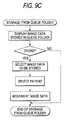
- the inputted image is temporarily stored as queue data (storage awaiting data) in the Queue folder 11 as shown in the flow chart of Fig. 9A.
- the image data temporarily stored in the Queue folder 11 is automatically deleted (disappears) in succession in order of data expiring a previously designated number of days (the number of storageable days, for example 3 days) as shown in the flow chart of Fig. 9B. If pieces of the image data temporarily stored in the Queue folder 11 exceed the number of determined pieces (storageable amount, for example 100 pieces), the image data exceeding the number of the determined pieces is deleted in order of older ones.
- the image display screen 90 shown in Fig. 6 is displayed, and then image data desired to be stored is selected.
- the drag-and-drop of the selected image data onto the patient list (patient 50a, 50b ...) displayed on the patient list screen 91 can move and store the image data in place.
- the present invention has been described with reference to an example of the ophthalmic apparatus, but the present invention should not be restricted thereto, and can be applied to various medical apparatuses that can obtain an image of a disease part or photographs the disease part, and that can obtain measured data.
- the external output is enabled only by drag-and-drop of the data onto the button (icon).
- the buttons (icons) corresponding to the different types (forms) of the external output, the different types (forms) of the external output can be executed in the consistent and same manner.
Landscapes
- Health & Medical Sciences (AREA)
- Engineering & Computer Science (AREA)
- Public Health (AREA)
- Biomedical Technology (AREA)
- Life Sciences & Earth Sciences (AREA)
- General Health & Medical Sciences (AREA)
- Medical Informatics (AREA)
- Epidemiology (AREA)
- Primary Health Care (AREA)
- Biophysics (AREA)
- Veterinary Medicine (AREA)
- General Business, Economics & Management (AREA)
- Business, Economics & Management (AREA)
- Ophthalmology & Optometry (AREA)
- Heart & Thoracic Surgery (AREA)
- Molecular Biology (AREA)
- Surgery (AREA)
- Animal Behavior & Ethology (AREA)
- Physics & Mathematics (AREA)
- Nuclear Medicine, Radiotherapy & Molecular Imaging (AREA)
- Radiology & Medical Imaging (AREA)
- Measuring And Recording Apparatus For Diagnosis (AREA)
- Processing Or Creating Images (AREA)
- Information Retrieval, Db Structures And Fs Structures Therefor (AREA)
- Medical Treatment And Welfare Office Work (AREA)
- Image Processing (AREA)
Abstract
Description
FAG fundus image, ICG fundus image, etc.), and any of them is selected and set using the pull-down menu.
Claims (10)
- A medical data processing method comprising the steps of:inputting or obtaining image data;displaying, on the same screen, the inputted or obtained image data and a selection button for selecting one of output types for outputting the image data;selecting a desired output type using the selection button; andoutputting the image data in accordance with the selected output type.
- The method of claim 1, wherein the step of displaying includes displaying the inputted or obtained image data on the same screen under a display condition of at least one of a patient, a time at which images were captured, and a method with which images were captured.
- The method of claim 1 or 2, wherein the output types include at least one of a type for outputting the image data in the form of E-mail to which the image data is attached, a type for outputting the image data as DICOM data, a type for outputting the image data as JPEG data, a type for outputting the image data to a printer, and a type for outputting the image data as medical account data.
- The method of any one of claims 1 to 3, wherein the step of selecting includes dragging and dropping the image data to be outputted, onto the selection button of a desired output type.
- The method of claim 4, wherein:the selection button includes a button that varies in at least one of configuration and pattern thereof depending on selection of an output type using a pull-down menu; andby the drag-and-drop of the image data onto the button, the image data is outputted in accordance with the selected output type.
- A medical data processing system comprising:input means for inputting or obtaining image data;display means for displaying, on the same screen, the inputted or obtained image data and a selection button for selecting one of output types for outputting the image data; andcontrol means for outputting the image data in accordance with an output type selected by the selection button.
- The system of claim 6, wherein the display means displays the inputted or obtained image data on the same screen under a display condition of at least one of a patient, a time at which images were captured, and a method with which images were captured.
- The system of claim 6 or 7, wherein the output types include at least one of a type for outputting the image data in the form of E-mail to which the image data is attached, a type for outputting the image data as DICOM data, a type for outputting the image data as JPEG data, a type for outputting the image data to a printer, and a type for outputting the image data as medical account data.
- The system of any one of claims 6 to 8, wherein the control means outputs the image data in accordance with the selected output type, by drag-and-drop of the image data onto the selection button.
- The system of claim 9, wherein:the selection button includes a button that varies in at least one of configuration and pattern thereof depending on selection of an output type using a pull-down menu; andby the drag-and-drop of the image data onto the button, the control means outputs the image data in accordance with the selected output type.
Applications Claiming Priority (2)
| Application Number | Priority Date | Filing Date | Title |
|---|---|---|---|
| JP2000221063 | 2000-07-17 | ||
| JP2000221063A JP2002032479A (en) | 2000-07-17 | 2000-07-17 | Method and system for medical treatment image management |
Publications (2)
| Publication Number | Publication Date |
|---|---|
| EP1176537A2 true EP1176537A2 (en) | 2002-01-30 |
| EP1176537A3 EP1176537A3 (en) | 2005-01-19 |
Family
ID=18715555
Family Applications (1)
| Application Number | Title | Priority Date | Filing Date |
|---|---|---|---|
| EP01117290A Withdrawn EP1176537A3 (en) | 2000-07-17 | 2001-07-17 | Medical data processing method and medical data processing system |
Country Status (3)
| Country | Link |
|---|---|
| US (1) | US20020059315A1 (en) |
| EP (1) | EP1176537A3 (en) |
| JP (1) | JP2002032479A (en) |
Cited By (1)
| Publication number | Priority date | Publication date | Assignee | Title |
|---|---|---|---|---|
| EP2704049A1 (en) * | 2012-08-30 | 2014-03-05 | Canon Kabushiki Kaisha | Diagnosis support apparatus and method |
Families Citing this family (8)
| Publication number | Priority date | Publication date | Assignee | Title |
|---|---|---|---|---|
| JP2003248723A (en) * | 2002-02-22 | 2003-09-05 | Konica Corp | Medical image transfer device, hospital system provided with same device, and method for transferring medical image |
| JP4490132B2 (en) * | 2004-02-13 | 2010-06-23 | テルモ株式会社 | Sphygmomanometer |
| JP4820680B2 (en) * | 2006-04-12 | 2011-11-24 | 株式会社東芝 | Medical image display device |
| JP5125128B2 (en) * | 2007-02-01 | 2013-01-23 | コニカミノルタエムジー株式会社 | Medical image management system and data management method |
| JP5305728B2 (en) * | 2008-05-08 | 2013-10-02 | 株式会社東芝 | Medical file management system and medical file management apparatus |
| US20120130741A1 (en) * | 2010-11-24 | 2012-05-24 | General Electric Company | Integrated patient information viewer interface |
| JP7055626B2 (en) * | 2017-12-05 | 2022-04-18 | キヤノンメディカルシステムズ株式会社 | Medical information processing equipment and programs |
| US11106347B1 (en) | 2019-06-04 | 2021-08-31 | Palantir Technologies Inc. | Systems and methods for high-scale top-down data analysis |
Family Cites Families (6)
| Publication number | Priority date | Publication date | Assignee | Title |
|---|---|---|---|---|
| EP0686927A1 (en) * | 1994-06-10 | 1995-12-13 | Agfa-Gevaert N.V. | System for supplying a processed radiographic image to a remote device |
| US5986662A (en) * | 1996-10-16 | 1999-11-16 | Vital Images, Inc. | Advanced diagnostic viewer employing automated protocol selection for volume-rendered imaging |
| US5987345A (en) * | 1996-11-29 | 1999-11-16 | Arch Development Corporation | Method and system for displaying medical images |
| AU5405798A (en) * | 1996-12-30 | 1998-07-31 | Imd Soft Ltd. | Medical information system |
| US5836877A (en) * | 1997-02-24 | 1998-11-17 | Lucid Inc | System for facilitating pathological examination of a lesion in tissue |
| GB2339128A (en) * | 1998-06-30 | 2000-01-12 | Ibm | Meyhod and system for transfering data using a graphical user interface |
-
2000
- 2000-07-17 JP JP2000221063A patent/JP2002032479A/en active Pending
-
2001
- 2001-07-17 US US09/905,994 patent/US20020059315A1/en not_active Abandoned
- 2001-07-17 EP EP01117290A patent/EP1176537A3/en not_active Withdrawn
Cited By (7)
| Publication number | Priority date | Publication date | Assignee | Title |
|---|---|---|---|---|
| EP2704049A1 (en) * | 2012-08-30 | 2014-03-05 | Canon Kabushiki Kaisha | Diagnosis support apparatus and method |
| CN103654696A (en) * | 2012-08-30 | 2014-03-26 | 佳能株式会社 | Diagnostic support device and diagnostic support method |
| CN103654696B (en) * | 2012-08-30 | 2015-12-02 | 佳能株式会社 | Diagnostic support device and diagnostic support method |
| CN105193380A (en) * | 2012-08-30 | 2015-12-30 | 佳能株式会社 | Diagnosis support apparatus and method |
| US9439562B2 (en) | 2012-08-30 | 2016-09-13 | Canon Kabushiki Kaisha | Diagnosis support apparatus and method |
| CN105193380B (en) * | 2012-08-30 | 2019-12-03 | 佳能株式会社 | Diagnosis support device and diagnosis support method |
| US10588505B2 (en) | 2012-08-30 | 2020-03-17 | Canon Kabushiki Kaisha | Diagnosis support apparatus and method |
Also Published As
| Publication number | Publication date |
|---|---|
| US20020059315A1 (en) | 2002-05-16 |
| JP2002032479A (en) | 2002-01-31 |
| EP1176537A3 (en) | 2005-01-19 |
Similar Documents
| Publication | Publication Date | Title |
|---|---|---|
| US7059721B2 (en) | Medical data processing method and medical data processing system | |
| US7818689B2 (en) | Information managing method, information managing apparatus, information managing program and storage medium | |
| EP1316911A2 (en) | Endoscope image filing system and endoscope image filing method | |
| JP2002200066A (en) | Image display control device | |
| JP4408555B2 (en) | Image and information processing apparatus | |
| JP2008181527A (en) | Medical information system | |
| JP2004013509A (en) | Image data layout display system for dental clinical and clinical use | |
| EP1434157A2 (en) | Image information processing apparatus and medical network system | |
| US20020059315A1 (en) | Medical data processing method and medical data processing system | |
| EP1178426A2 (en) | Medical data managing system | |
| US20040227821A1 (en) | Image management method, apparatus and program | |
| JP5228845B2 (en) | Image display device | |
| JP5228848B2 (en) | Image display device | |
| JP2004070942A (en) | Image filing device | |
| JP5659792B2 (en) | Image creation device, image display device, image creation method, and image display method | |
| JP2000033072A (en) | Endoscope image filing system | |
| JP4460311B2 (en) | Medical chart creation device and program | |
| JP2004282224A (en) | Photo printer and control method thereof | |
| JP5120231B2 (en) | Image display device | |
| JP2005118074A (en) | Method and device for controlling inspection device | |
| JP2005196662A (en) | Dental practice support device | |
| JP5522169B2 (en) | Inspection data display device, graph creation method and program | |
| JP2004348687A (en) | Inspection management method and system | |
| JPH0339137A (en) | Controlling system for information on roentgen examination | |
| JP4264729B2 (en) | Medical chart creation device and program |
Legal Events
| Date | Code | Title | Description |
|---|---|---|---|
| PUAI | Public reference made under article 153(3) epc to a published international application that has entered the european phase |
Free format text: ORIGINAL CODE: 0009012 |
|
| AK | Designated contracting states |
Kind code of ref document: A2 Designated state(s): AT BE CH CY DE DK ES FI FR GB GR IE IT LI LU MC NL PT SE TR |
|
| AX | Request for extension of the european patent |
Free format text: AL;LT;LV;MK;RO;SI |
|
| PUAL | Search report despatched |
Free format text: ORIGINAL CODE: 0009013 |
|
| AK | Designated contracting states |
Kind code of ref document: A3 Designated state(s): AT BE CH CY DE DK ES FI FR GB GR IE IT LI LU MC NL PT SE TR |
|
| AX | Request for extension of the european patent |
Extension state: AL LT LV MK RO SI |
|
| AKX | Designation fees paid | ||
| STAA | Information on the status of an ep patent application or granted ep patent |
Free format text: STATUS: THE APPLICATION IS DEEMED TO BE WITHDRAWN |
|
| 18D | Application deemed to be withdrawn |
Effective date: 20050720 |
|
| REG | Reference to a national code |
Ref country code: DE Ref legal event code: 8566 |