EP1176429A2 - Portable type distance measuring apparatus - Google Patents
Portable type distance measuring apparatus Download PDFInfo
- Publication number
- EP1176429A2 EP1176429A2 EP01116523A EP01116523A EP1176429A2 EP 1176429 A2 EP1176429 A2 EP 1176429A2 EP 01116523 A EP01116523 A EP 01116523A EP 01116523 A EP01116523 A EP 01116523A EP 1176429 A2 EP1176429 A2 EP 1176429A2
- Authority
- EP
- European Patent Office
- Prior art keywords
- distance measuring
- unit
- main body
- light
- target
- Prior art date
- Legal status (The legal status is an assumption and is not a legal conclusion. Google has not performed a legal analysis and makes no representation as to the accuracy of the status listed.)
- Granted
Links
- 238000005259 measurement Methods 0.000 claims abstract description 87
- 238000004891 communication Methods 0.000 claims abstract description 20
- 238000012545 processing Methods 0.000 claims abstract description 3
- 230000000379 polymerizing effect Effects 0.000 claims description 2
- 238000013500 data storage Methods 0.000 description 6
- 230000006870 function Effects 0.000 description 6
- 230000003287 optical effect Effects 0.000 description 4
- 238000010586 diagram Methods 0.000 description 2
- 239000000284 extract Substances 0.000 description 2
- 238000001514 detection method Methods 0.000 description 1
- 230000004069 differentiation Effects 0.000 description 1
- 239000000463 material Substances 0.000 description 1
- 238000011017 operating method Methods 0.000 description 1
- 230000002093 peripheral effect Effects 0.000 description 1
Images


Classifications
-
- G—PHYSICS
- G01—MEASURING; TESTING
- G01S—RADIO DIRECTION-FINDING; RADIO NAVIGATION; DETERMINING DISTANCE OR VELOCITY BY USE OF RADIO WAVES; LOCATING OR PRESENCE-DETECTING BY USE OF THE REFLECTION OR RERADIATION OF RADIO WAVES; ANALOGOUS ARRANGEMENTS USING OTHER WAVES
- G01S17/00—Systems using the reflection or reradiation of electromagnetic waves other than radio waves, e.g. lidar systems
- G01S17/02—Systems using the reflection of electromagnetic waves other than radio waves
- G01S17/06—Systems determining position data of a target
- G01S17/08—Systems determining position data of a target for measuring distance only
- G01S17/32—Systems determining position data of a target for measuring distance only using transmission of continuous waves, whether amplitude-, frequency-, or phase-modulated, or unmodulated
- G01S17/36—Systems determining position data of a target for measuring distance only using transmission of continuous waves, whether amplitude-, frequency-, or phase-modulated, or unmodulated with phase comparison between the received signal and the contemporaneously transmitted signal
-
- G—PHYSICS
- G01—MEASURING; TESTING
- G01C—MEASURING DISTANCES, LEVELS OR BEARINGS; SURVEYING; NAVIGATION; GYROSCOPIC INSTRUMENTS; PHOTOGRAMMETRY OR VIDEOGRAMMETRY
- G01C15/00—Surveying instruments or accessories not provided for in groups G01C1/00 - G01C13/00
- G01C15/002—Active optical surveying means
- G01C15/004—Reference lines, planes or sectors
- G01C15/006—Detectors therefor
-
- G—PHYSICS
- G01—MEASURING; TESTING
- G01S—RADIO DIRECTION-FINDING; RADIO NAVIGATION; DETERMINING DISTANCE OR VELOCITY BY USE OF RADIO WAVES; LOCATING OR PRESENCE-DETECTING BY USE OF THE REFLECTION OR RERADIATION OF RADIO WAVES; ANALOGOUS ARRANGEMENTS USING OTHER WAVES
- G01S17/00—Systems using the reflection or reradiation of electromagnetic waves other than radio waves, e.g. lidar systems
- G01S17/02—Systems using the reflection of electromagnetic waves other than radio waves
- G01S17/06—Systems determining position data of a target
-
- G—PHYSICS
- G01—MEASURING; TESTING
- G01S—RADIO DIRECTION-FINDING; RADIO NAVIGATION; DETERMINING DISTANCE OR VELOCITY BY USE OF RADIO WAVES; LOCATING OR PRESENCE-DETECTING BY USE OF THE REFLECTION OR RERADIATION OF RADIO WAVES; ANALOGOUS ARRANGEMENTS USING OTHER WAVES
- G01S7/00—Details of systems according to groups G01S13/00, G01S15/00, G01S17/00
- G01S7/48—Details of systems according to groups G01S13/00, G01S15/00, G01S17/00 of systems according to group G01S17/00
- G01S7/481—Constructional features, e.g. arrangements of optical elements
-
- G—PHYSICS
- G01—MEASURING; TESTING
- G01S—RADIO DIRECTION-FINDING; RADIO NAVIGATION; DETERMINING DISTANCE OR VELOCITY BY USE OF RADIO WAVES; LOCATING OR PRESENCE-DETECTING BY USE OF THE REFLECTION OR RERADIATION OF RADIO WAVES; ANALOGOUS ARRANGEMENTS USING OTHER WAVES
- G01S7/00—Details of systems according to groups G01S13/00, G01S15/00, G01S17/00
- G01S7/48—Details of systems according to groups G01S13/00, G01S15/00, G01S17/00 of systems according to group G01S17/00
- G01S7/497—Means for monitoring or calibrating
Definitions
- the present invention relates to a portable type distance measuring apparatus, by which survey operation can be performed in easier manner.
- portable type distance measuring apparatuses with light wave distance measuring functions have been brought to the commercial stage.
- the portable type distance measuring apparatuses have been known and used in the past.
- the portable type distance measuring apparatus with the light wave distance measuring function is a high-performance distance measuring system using a reflecting prism as a target object, and it may not be adequate to simply name it as a portable type distance measuring apparatus.
- a portable type distance measuring apparatus using an ultrasonic wave has been known, but it is low in accuracy and narrow in a range of which distance measurement can be performed, and performance characteristics are not high enough for the actual execution of survey operation.
- the portable type distance measuring apparatus with the light wave distance measuring function has been produced recently for practical use.
- This apparatus uses a light of electro magnetic wave type and enable to measure a distance up to the target object with high accuracy using pulse number and phase of pulsed light.
- For the measurement of short distance up to about 100 m, it is used as a non-prism type without using a reflecting prism as the target object.
- the reflecting prism is used, distance measurement can be achieved for a long distance.
- a portable type distance measuring apparatus 1 is designed in such size and shape that it can be handled and carried by one hand. It is a portable type distance measuring apparatus of non-prism type without using a reflecting prism.
- the portable type distance measuring apparatus 1 comprises a distance measuring unit (not shown), an azimuth finder, and a power source unit such as battery incorporated in it.
- a distance measuring light from the distance measuring unit is projected from a projection unit 2 provided on one surface of the portable type distance measuring apparatus 1.
- a display unit 3 and an operation unit 4 are arranged on upper surface of the portable type distance measuring apparatus 1.
- the operation unit 4 has various types of pushbuttons such as a power switch, an operation switch, etc. By operating these pushbuttons, a distance measuring light 6 is projected from the projection unit 2 to a measurement plane 5 of a target object. As the distance measuring light 6, a visible light is used. An operator can visually confirm a projected position of the distance measuring light 6 on the measurement plane 5.
- the distance measuring light 6 reflected by the measurement plane 5 enters the distance measuring unit via the projection unit 2.
- the distance measuring unit a distance between the portable type distance measuring apparatus 1 and the measurement plane 5 (target object) is measured, and the result of measurement is displayed on the display unit 3.
- the conventional portable type distance measuring apparatus as described above is a light wave distance measuring instrument and can measure the distance to the target object and the measurement plane with high accuracy. To provide portability, it is designed as a non-prism type.
- the light wave distance measuring instrument is used to measure a distance by receiving a reflection light from the measurement plane (target object), and it is used on the assumption that the measurement plane is present. In case the measurement plane is present at a position opposite to the portable type distance measuring apparatus, measurement can be made effectively. In case there is no target object, it is not possible to determine a position apart from the portable type distance measuring apparatus 1 by a given distance. Also, it is not possible to determine positions with a given spacing along the projecting direction of the distance measuring light.
- the measurement plane is a plane tilted with respect to the distance measuring light or ground surface
- the portable type distance measuring apparatus comprises an apparatus main body having a distance measuring unit for measuring a distance by projecting a distance measuring light, a control unit for controlling the distance measuring unit and for processing measurement data from the distance measuring unit and a transmitting unit to emit a communication light including the measurement data to a distance measuring direction, and a target unit having a display unit, an operation unit and a photodetection unit for receiving the communication light, wherein the target unit is removably mounted on the apparatus main body so that the target unit may be used as an object to be measured for distance measurement when necessary.
- the present invention provides a portable type distance measuring apparatus as described above, wherein the apparatus main body further comprises a display unit and an operation unit, and the apparatus main body can be operated under condition that the target unit is separated. Further, the present invention provides a portable type distance measuring apparatus as described above, wherein each of the apparatus main body and the target unit comprises a power source unit and a control unit so that the apparatus main body and the target unit can be operated independently. Also, the present invention provides a portable type distance measuring apparatus as described above, wherein the distance measuring light also serves as the communication light, the transmitting unit comprises a modulation circuit for polymerizing the measurement data to the distance measuring light, and the target unit comprises a demodulation circuit for separating and extracting the measurement data from the distance measuring light.
- the present invention provides a portable type distance measuring apparatus as describe above, wherein at least one of the apparatus main body and the target unit is provided with an arithmetic operation program for obtaining survey results as desired based on the distance measurement data. Also, the present invention provides a portable type distance measuring apparatus as described above, wherein the apparatus main body and the target unit are integrated with each other, and the distance measurement data is delivered and received between the apparatus main body and the target unit by the distance measuring light. Further, the present invention provides a portable type distance measuring apparatus as described above, wherein the distance measuring light is a visible light and has a pointer function.
- the present invention provides a portable type distance measuring apparatus as described above, wherein a visible laser pointer beam is projected to a direction opposite to a projecting direction of the distance measuring light. Further, the present invention provides a portable type distance measuring apparatus as describe above, wherein a bubble tube for detecting horizontality of the distance measuring light is provided on the apparatus main body. Also, the present invention provides a portable type distance measuring apparatus as described above, wherein the bubble tube is an electric bubble tube for detecting inclination, and a tilt angle is displayed on the display unit based on an output corresponding to the inclination.
- a portable type distance measuring apparatus 10 comprises an apparatus main body 11 and a target unit 12.
- the target unit 12 is removably mounted on the apparatus main body 11.
- the apparatus main body 11 and the target unit 12 can be handled and carried by one hand regardless of whether these are separated from each other or integrated, and these are designed in such size and shape as to be easily handled and carried.
- the apparatus main body 11 and the target unit 12 are electrically connected with each other.
- the target unit 12 comprises a target display unit 13, a target operation unit 14, and a photodetection unit 15 which also serves as a reflection unit. It is designed as a self-standing type with the photodetection unit 15 directed toward the apparatus main body 11.
- a main body display unit 16 and a main body operation unit 17 On a mounting surface of the apparatus main body 11 where the target unit 12 is to be mounted, there are provided a main body display unit 16 and a main body operation unit 17. On the main body operation unit 17, operation buttons are arranged at lower level than the mounting.surface so that no trouble occurs when the target unit 12 is mounted on it. On the target unit 12 and the apparatus main body 11, connector units 18 and 19 are disposed respectively to connect them with each other when the target unit 12 is mounted. On a portion of the apparatus main body 11 other than the portion where the target unit 12 is mounted, an electric bubble tube 20 is disposed, and a tilt detected by the electric bubble tube 20 is displayed on the target display unit 13 or the main body display unit 16. As the electric bubble tube, a bubble tube of capacitance type or of resistance type may be used. As a tilt detector other than the electric bubble tube, a mechanical detector of pendulum type may be used.
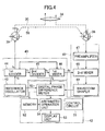
- the apparatus main body 11 mainly comprises a main body control unit 21, a distance measuring unit 22, a modulation circuit 23, a main power source unit 24, the main body display unit 16, the main body operation unit 17 and the electric bubble tube 20 as described above, and an azimuth finder 25.
- the main body control unit 21 incorporates a sequence program for light wave measurement in it.
- the distance measuring unit 22 is driven and controlled by the main body control unit 21.
- the modulation circuit 23 is driven and controlled by the main body control unit 21, modulates a distance measuring light 30, and polymerizes communication data to the distance measuring light 30.
- the target unit 12 primarily comprises a target control unit 26 connected to the main body control unit 21 via the connector units 18 and 19, a data storage unit 27 connected to the target control unit 26 and used for storing distance measurement data, a target power source unit 28 connected to the main power source unit 24 via the connector units 18 and 19 and charged by the main power source unit 24, the target display unit 13, the target operation unit 14 and the photodetection unit 15 as described above.
- a survey program is incorporated for calculating a distance between two points based on distance measurement data or for calculating an area of predetermined range based on the distance measurement data and an azimuth angle.
- the storage unit 27 may be provided on the apparatus main body 11, or the survey program may be incorporated in the main body control unit 21. Both the apparatus main body 11 and the target unit 12 may be provided with the storage unit and the survey program.
- a visible laser beam with high visibility is used, which enable to measure a long distance and has a pointer function.
- the apparatus main body 11 and the target unit 12 are integrated with each other, and the distance is measured by a non-prism type.
- a horizontality is confirmed by the electric bubble tube 20 mounted on the apparatus main body 11.
- the distance measuring light 30 is also set at a horizontal position. That is, a horizontal distance to a target object, i.e. the measurement plane 5, is measured.
- a tilted distance can be converted to the horizontal distance.
- the tilt of the apparatus main body 11 is detected by using the electric bubble tube 20 as the bubble tube, from which a tilt angle is electrically outputted, and the tilt angle is displayed on the display unit. Based on the displayed value, the horizontal distance is calculated. Further, it is easy and possible to incorporate an arithmetic operation program and to convert the tilted distance to the horizontal distance by a single switching operation.
- a power switch is turned on by the target operation unit 14, and measurement is started by operating a measurement starting button, and other necessary operating procedures are carried out.
- An instruction of an operator inputted from the target operation unit 14 is inputted to the main body control unit 21 via the target control unit 26 and the connector units 18 and 19.
- the main body control unit 21 issues a measurement command to the distance measuring unit 22.
- the distance measuring unit 22 is driven by the measurement command from the main body control unit 21, and the distance measuring light 30 is irradiated. A reflected distance measuring light 30' reflected from the measurement plane 5 is received, and light wave distance measurement is performed. The distance measurement data is inputted to the main body control unit 21.
- the main body control unit 21 inputs the distance measurement data and the azimuth angle detected by the azimuth finder 25 to the target control unit 26 via the connector units 18 and 19.
- the target control unit 26 controls the data storage unit 27 to store the distance measurement data from the main body control unit 21, and measurement result is displayed on the target display unit 13.
- the results of measurement are sequentially stored in the data storage unit 27.
- the data storage unit 27 When measurement operation for all points has been completed during the measurement operation, it is possible to call the data at any desired time and to display it on the target display unit 13. Displays of the data are performed with orders of measurement and the azimuth angle, and differentiation is made for each measuring point.
- the target control unit 26 Based on the incorporated survey program, calculates an area of a surveyed range from the measurement data and the azimuth angles at the plurality of points.
- the target unit 12 is separated from the apparatus main body 11 as shown in Fig. 2, and it is used as a target.
- the power is turned on from the main body operation unit 17.
- the main body control unit 21 displays the result of detection from the azimuth finder 25 on the main body display unit 16.
- the operator determines measurement azimuth and installs the apparatus main body 11 so that it is at the determined azimuth.
- the main body operation unit 17 is operated, and the distance measuring light 30 is projected from the distance measuring unit 22, and measurement is started.
- the modulation circuit 23 is operated. By modulating the distance measuring light 30, the distance measurement results and the survey data such as the azimuth angle are polymerized to the distance measuring light 30 as communication data.
- the operator moves under the condition where the distance measuring light 30 is projected to the photodetection unit 15, and installs the target unit 12 at a measuring point.
- the photodetection unit. 15 reflects the distance measuring light 30 to the apparatus main body 11.
- the apparatus main body 11 receives the reflection light from the photodetection unit 15, and the distance measuring unit 22 measures a distance between the apparatus main body 11 and the target unit 12.
- the result of distance measurement is inputted to the main body control unit 21.
- the main body control unit 21 performs modulation control of the modulation circuit 23 based on the distance measurement data. According to a control command from the main body control unit 21, the modulation circuit 23 polymerizes the distance measurement data to the distance measuring light 30 as communication data.
- Peripheral region of the photodetection unit 15 is designed as a plane, which easily reflects the light toward the apparatus main body 11. For instance, the region is made of a material which has a retroreflection property to some extent.
- the photodetection unit 15 receives the distance measuring light 30, converts it to a photodetection signal and inputs it to the target control unit 26.
- the target control unit 26 separates and extracts the communication data from the photodetection signal.
- the communication data thus separated and extracted is stored in the data storage unit 27 as a distance measurement data.
- the target unit 12 is moved, and measurements are repeatedly performed along a straight line using the distance measuring light 30 as a guide light. Results of the measurements are stored in the data storage unit 27 together with orders of the measurements.
- spacing length should be set to the target control unit 26 from the target operation unit 14. Then, the target control unit 26 compares the measurement result with the preset spacing length and calculates. Then, lamps (not shown) are lighted up each at the predetermined spacing, or movement at the predetermined spacing length is displayed on the target display unit 13.
- the target display unit 13 may be provided on opposite side of the photodetection unit 15 or on top surface of the target unit 12 when it is erected.
- a rechargeable type or.a dry cell type, or both may be used.
- non-prism distance measurement mode there are a pulse mode and a phase difference mode of a continuous light. In case of a visible light, the latter is generally used. Description will be given below on the phase difference mode.
- a light wave distance measuring instrument comprises a light emitting side analog circuit 40, a light receiving side analog circuit 41, and a digital circuit 42.
- the light emitting side analog circuit 40 comprises a reference oscillator 43, a first divider 44 for being inputted from the reference oscillator 43 and for outputting to a light emitting element 39, a second divider 45 for being inputted from the first divider 44, and a first mixer 46 for being inputted from the first divider 44 and the second divider 45.
- the light receiving side analog circuit 41 comprises a preamplifier 47 for being inputted from a photodetection element 38, a second mixer 48 for being inputted from the preamplifier 47 and the first mixer 46, and a waveform shaper 49 for being inputted from the second mixer 48 and for outputting to the digital circuit 42.
- the digital circuit 42 comprises a digital phase difference meter 50 inputted from the reference oscillator 43, the second divider 45, and the waveform shaper 49, a memory 52 inputted from the digital phase difference meter 50, and an arithmetic operation unit 54 inputted from the digital phase difference meter 50 and the memory 52 and for outputting to a display unit 53.
- the digital circuit 42 further comprises a control circuit 51.
- This signal is sent to the light emitting element 39, and the light emitting element 39 emits an infrared modulation light with frequency of 1.5 MHz.
- the modulated light from the light emitting element 39 is selectively turned to an internal reference light 56 or the distance measuring light 30.
- the distance measuring light 30 is sent to an object to be measured (not shown) disposed at a target point via an objective lens 34. It is then reflected and reaches the photodetection element 38 via the objective lens 34 again.
- a light beam entering the photodetection element 38 contains a light component of 1.5 MHz and a light component with phase difference corresponding to the distance.
- This signal with frequency f3 is further supplied to the second mixer 48 of the light receiving side analog circuit 41.
- This signal is shaped by the waveform shaper 49 and is sent to the digital phase difference meter 50 at the digital circuit 42.
- the signal with frequency f2 from the second divider 45 is sent to the digital phase difference meter 50 as a reference signal and the digital phase difference meter 50 detects the phase difference corresponding to the distance.
- the size of the detected phase difference is digitally measured according to a signal with frequency f0 from the reference oscillator 43, and this value is supplied to the arithmetic operation unit 54.
- the arithmetic operation unit 54 calculates the distance to the object to be measured based on the distance measurement data and calculates a distance between two points, an area of a predetermined range, etc., based on distance measurement data at two points.
- the apparatus main body 11 is designed to project a rear laser pointer beam 61 from a rear end surface, and the rear laser pointer beam 61 is on the same straight line as the distance measuring light 30 which is projected in a front direction.
- the rear laser pointer beam projected in a backward direction is a visible laser beam.
- the rear laser pointer beam 61 is used to align with a reference point 62 at a rear position. When the rear position is determined, the measuring direction is also determined, and this further facilitates the measurement operation using the target unit 12.
- Fig. 6 shows another embodiment of the present invention.
- the apparatus main body 11 is integrated with the target unit 12
- signals are given and received between these two units via optical communication.
- Fig. 6 the distance measuring unit 22 in the apparatus main body 11 is shown in detail.
- reference numeral 32 denotes a distance measuring light emitting unit, and a driver (not shown; see the light emitting side analog circuit 40 in Fig. 4) of the distance measuring light emitting unit 32 is modulated by the modulation circuit 23.
- the modulated distance measuring light is selectively divided to an internal reference light 30r and the distance measuring light 30 by a chopper 29.
- the distance measuring light 30 is projected to a target object via a prism 35 and a half-mirror 36.
- the internal reference light 30r passes through the prism 35 and a density filter 31 and enters a distance measuring light receiving unit 33.
- a part of the distance measuring light 30 is split by the half-mirror 36, and the split light 30b enters the photodetection element 38 of the photodetection unit 15 via the mirror 37. From the photodetection element 38, a photodetection signal is inputted to the target control unit 26.
- the density filter 31 turns light amount of the internal reference light 30r and the reflected distance measuring light 30' to a constant level, and these beams enter the distance measuring light receiving unit 33.
- light wave distance measurement is performed. The result of measurement is polymerized to the distance measuring light 30 by the modulation circuit 23 as communication data.
- Distance measurement data is polymerized to the split light 30b, and the target control unit 26 separates and extracts the distance measurement data from the photodetection signal from the photodetection element 38.
- the distance measurement data thus separated and extracted is displayed on the target display unit 13 or it is stored in the data storage unit 27.
- the communication between the apparatus main body 11 and the target unit 12 may be radio communication instead of optical communication.
- another optical communication means for optical communication may be provided, which uses a different light from the distance measuring light.
- distance measurement can be achieved in a non-prism mode. Even when there is no suitable target object and distance measurement in a non-prism mode is difficult to perform, the target unit can be used as the target object. Thus, distance can be measured regardless of measuring environment. Because the target unit is provided with a reflection unit, reflection can be achieved with high efficiency. Distance measurement for a long distance can be performed. Using a distance measuring light as a guide light, a measuring point can be set as desired, or measuring points can be set with a given spacing.
Landscapes
- Physics & Mathematics (AREA)
- Engineering & Computer Science (AREA)
- General Physics & Mathematics (AREA)
- Radar, Positioning & Navigation (AREA)
- Remote Sensing (AREA)
- Electromagnetism (AREA)
- Computer Networks & Wireless Communication (AREA)
- Optical Radar Systems And Details Thereof (AREA)
- Measurement Of Optical Distance (AREA)
Abstract
Description
- The present invention relates to a portable type distance measuring apparatus, by which survey operation can be performed in easier manner.
- In recent years, portable type distance measuring apparatuses with light wave distance measuring functions have been brought to the commercial stage. The portable type distance measuring apparatuses have been known and used in the past. However, the portable type distance measuring apparatus with the light wave distance measuring function is a high-performance distance measuring system using a reflecting prism as a target object, and it may not be adequate to simply name it as a portable type distance measuring apparatus. Also, a portable type distance measuring apparatus using an ultrasonic wave has been known, but it is low in accuracy and narrow in a range of which distance measurement can be performed, and performance characteristics are not high enough for the actual execution of survey operation.
- The portable type distance measuring apparatus with the light wave distance measuring function has been produced recently for practical use. This apparatus uses a light of electro magnetic wave type and enable to measure a distance up to the target object with high accuracy using pulse number and phase of pulsed light. For the measurement of short distance (up to about 100 m), it is used as a non-prism type without using a reflecting prism as the target object. When the reflecting prism is used, distance measurement can be achieved for a long distance.
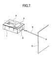
- Referring to Fig. 7, description will be given below on a conventional portable type distance measuring apparatus.
- A portable type distance measuring apparatus 1 is designed in such size and shape that it can be handled and carried by one hand. It is a portable type distance measuring apparatus of non-prism type without using a reflecting prism.
- The portable type distance measuring apparatus 1 comprises a distance measuring unit (not shown), an azimuth finder, and a power source unit such as battery incorporated in it. A distance measuring light from the distance measuring unit is projected from a
projection unit 2 provided on one surface of the portable type distance measuring apparatus 1. On upper surface of the portable type distance measuring apparatus 1, adisplay unit 3 and anoperation unit 4 are arranged. Theoperation unit 4 has various types of pushbuttons such as a power switch, an operation switch, etc. By operating these pushbuttons, adistance measuring light 6 is projected from theprojection unit 2 to ameasurement plane 5 of a target object. As thedistance measuring light 6, a visible light is used. An operator can visually confirm a projected position of thedistance measuring light 6 on themeasurement plane 5. Thedistance measuring light 6 reflected by themeasurement plane 5 enters the distance measuring unit via theprojection unit 2. By the distance measuring unit, a distance between the portable type distance measuring apparatus 1 and the measurement plane 5 (target object) is measured, and the result of measurement is displayed on thedisplay unit 3. - The conventional portable type distance measuring apparatus as described above is a light wave distance measuring instrument and can measure the distance to the target object and the measurement plane with high accuracy. To provide portability, it is designed as a non-prism type. The light wave distance measuring instrument is used to measure a distance by receiving a reflection light from the measurement plane (target object), and it is used on the assumption that the measurement plane is present. In case the measurement plane is present at a position opposite to the portable type distance measuring apparatus, measurement can be made effectively. In case there is no target object, it is not possible to determine a position apart from the portable type distance measuring apparatus 1 by a given distance. Also, it is not possible to determine positions with a given spacing along the projecting direction of the distance measuring light.
- Further, in case the measurement plane is a plane tilted with respect to the distance measuring light or ground surface, there are much variations on the measured values according to the properties of the surface to be projected. That is because, among the regions projected by the distance measuring light, an area with higher reflection is selected as a measuring point.
- It is an object of the present invention to provide a portable type distance measuring apparatus, which can be used as a distance measuring system of a non-prism type in case there is a target object suitable for measurement, and which can be used as a distance measuring system of a prism type in case there is no target object suitable for measurement.
- To attain the above object, the portable type distance measuring apparatus according to the present invention comprises an apparatus main body having a distance measuring unit for measuring a distance by projecting a distance measuring light, a control unit for controlling the distance measuring unit and for processing measurement data from the distance measuring unit and a transmitting unit to emit a communication light including the measurement data to a distance measuring direction, and a target unit having a display unit, an operation unit and a photodetection unit for receiving the communication light, wherein the target unit is removably mounted on the apparatus main body so that the target unit may be used as an object to be measured for distance measurement when necessary. Also, the present invention provides a portable type distance measuring apparatus as described above, wherein the apparatus main body further comprises a display unit and an operation unit, and the apparatus main body can be operated under condition that the target unit is separated. Further, the present invention provides a portable type distance measuring apparatus as described above, wherein each of the apparatus main body and the target unit comprises a power source unit and a control unit so that the apparatus main body and the target unit can be operated independently. Also, the present invention provides a portable type distance measuring apparatus as described above, wherein the distance measuring light also serves as the communication light, the transmitting unit comprises a modulation circuit for polymerizing the measurement data to the distance measuring light, and the target unit comprises a demodulation circuit for separating and extracting the measurement data from the distance measuring light. Further, the present invention provides a portable type distance measuring apparatus as describe above, wherein at least one of the apparatus main body and the target unit is provided with an arithmetic operation program for obtaining survey results as desired based on the distance measurement data. Also, the present invention provides a portable type distance measuring apparatus as described above, wherein the apparatus main body and the target unit are integrated with each other, and the distance measurement data is delivered and received between the apparatus main body and the target unit by the distance measuring light. Further, the present invention provides a portable type distance measuring apparatus as described above, wherein the distance measuring light is a visible light and has a pointer function. Also, the present invention provides a portable type distance measuring apparatus as described above, wherein a visible laser pointer beam is projected to a direction opposite to a projecting direction of the distance measuring light. Further, the present invention provides a portable type distance measuring apparatus as describe above, wherein a bubble tube for detecting horizontality of the distance measuring light is provided on the apparatus main body. Also, the present invention provides a portable type distance measuring apparatus as described above, wherein the bubble tube is an electric bubble tube for detecting inclination, and a tilt angle is displayed on the display unit based on an output corresponding to the inclination.
-
- Fig. 1
- is a perspective view of an embodiment of the present invention where an apparatus main body and a target unit are integrated;
- Fig. 2
- is a perspective view of an embodiment of the present invention where an apparatus main body and a target unit are separated from each other;
- Fig. 3
- is a block diagram of the embodiment of the present invention as given above;
- Fig. 4
- is a distance measuring circuit diagram of a light wave distance measuring instrument used in the embodiment;
- Fig. 5
- is a perspective view of another embodiment of the present invention;
- Fig. 6
- represents still another embodiment of the present invention, showing a case where signals are delivered and received between the apparatus main body and the target unit by means of a part of a distance measuring light; and
- Fig. 7
- is a perspective view of a conventional system.
- Description will be given below on embodiments of the present invention referring to the drawings.
- As shown in Fig. 1 and Fig. 2, a portable type
distance measuring apparatus 10 comprises an apparatusmain body 11 and atarget unit 12. Thetarget unit 12 is removably mounted on the apparatusmain body 11. The apparatusmain body 11 and thetarget unit 12 can be handled and carried by one hand regardless of whether these are separated from each other or integrated, and these are designed in such size and shape as to be easily handled and carried. When these component units are integrated, the apparatusmain body 11 and thetarget unit 12 are electrically connected with each other. - Now, description will be given on the apparatus
main body 11 and thetarget unit 12. - The
target unit 12 comprises atarget display unit 13, atarget operation unit 14, and aphotodetection unit 15 which also serves as a reflection unit. It is designed as a self-standing type with thephotodetection unit 15 directed toward the apparatusmain body 11. - On a mounting surface of the apparatus
main body 11 where thetarget unit 12 is to be mounted, there are provided a mainbody display unit 16 and a mainbody operation unit 17. On the mainbody operation unit 17, operation buttons are arranged at lower level than the mounting.surface so that no trouble occurs when thetarget unit 12 is mounted on it. On thetarget unit 12 and the apparatusmain body 11,connector units target unit 12 is mounted. On a portion of the apparatusmain body 11 other than the portion where thetarget unit 12 is mounted, anelectric bubble tube 20 is disposed, and a tilt detected by theelectric bubble tube 20 is displayed on thetarget display unit 13 or the mainbody display unit 16. As the electric bubble tube, a bubble tube of capacitance type or of resistance type may be used. As a tilt detector other than the electric bubble tube, a mechanical detector of pendulum type may be used. - Further, description will be given below referring to Fig. 3.
- The apparatus
main body 11 mainly comprises a mainbody control unit 21, adistance measuring unit 22, amodulation circuit 23, a mainpower source unit 24, the mainbody display unit 16, the mainbody operation unit 17 and theelectric bubble tube 20 as described above, and anazimuth finder 25. The mainbody control unit 21 incorporates a sequence program for light wave measurement in it. Thedistance measuring unit 22 is driven and controlled by the mainbody control unit 21. Themodulation circuit 23 is driven and controlled by the mainbody control unit 21, modulates adistance measuring light 30, and polymerizes communication data to thedistance measuring light 30. - The
target unit 12 primarily comprises atarget control unit 26 connected to the mainbody control unit 21 via theconnector units data storage unit 27 connected to thetarget control unit 26 and used for storing distance measurement data, a targetpower source unit 28 connected to the mainpower source unit 24 via theconnector units power source unit 24, thetarget display unit 13, thetarget operation unit 14 and thephotodetection unit 15 as described above. In thetarget control unit 26, a survey program is incorporated for calculating a distance between two points based on distance measurement data or for calculating an area of predetermined range based on the distance measurement data and an azimuth angle. Thestorage unit 27 may be provided on the apparatusmain body 11, or the survey program may be incorporated in the mainbody control unit 21. Both the apparatusmain body 11 and thetarget unit 12 may be provided with the storage unit and the survey program. - As the
distance measuring light 30 projected from thedistance measuring unit 22, a visible laser beam with high visibility is used, which enable to measure a long distance and has a pointer function. - In the following, description will be given on operation.
- First, description will be given on measurement in case there is the
measurement plane 5 suitable for measurement as shown in Fig. 1. - In case there is the
measurement plane 5 suitable for measurement, the apparatusmain body 11 and thetarget unit 12 are integrated with each other, and the distance is measured by a non-prism type. - A horizontality is confirmed by the
electric bubble tube 20 mounted on the apparatusmain body 11. When the apparatusmain body 11 is set at a horizontal position, thedistance measuring light 30 is also set at a horizontal position. That is, a horizontal distance to a target object, i.e. themeasurement plane 5, is measured. - When a tilt is known, a tilted distance can be converted to the horizontal distance. The tilt of the apparatus
main body 11 is detected by using theelectric bubble tube 20 as the bubble tube, from which a tilt angle is electrically outputted, and the tilt angle is displayed on the display unit. Based on the displayed value, the horizontal distance is calculated. Further, it is easy and possible to incorporate an arithmetic operation program and to convert the tilted distance to the horizontal distance by a single switching operation. - A power switch is turned on by the
target operation unit 14, and measurement is started by operating a measurement starting button, and other necessary operating procedures are carried out. - An instruction of an operator inputted from the
target operation unit 14 is inputted to the mainbody control unit 21 via thetarget control unit 26 and theconnector units body control unit 21 issues a measurement command to thedistance measuring unit 22. - The
distance measuring unit 22 is driven by the measurement command from the mainbody control unit 21, and thedistance measuring light 30 is irradiated. A reflected distance measuring light 30' reflected from themeasurement plane 5 is received, and light wave distance measurement is performed. The distance measurement data is inputted to the mainbody control unit 21. The mainbody control unit 21 inputs the distance measurement data and the azimuth angle detected by theazimuth finder 25 to thetarget control unit 26 via theconnector units - The
target control unit 26 controls thedata storage unit 27 to store the distance measurement data from the mainbody control unit 21, and measurement result is displayed on thetarget display unit 13. - In case measurement is performed on a plurality of points, the results of measurement are sequentially stored in the
data storage unit 27. When measurement operation for all points has been completed during the measurement operation, it is possible to call the data at any desired time and to display it on thetarget display unit 13. Displays of the data are performed with orders of measurement and the azimuth angle, and differentiation is made for each measuring point. Based on the incorporated survey program, thetarget control unit 26 calculates an area of a surveyed range from the measurement data and the azimuth angles at the plurality of points. - Next, in case there is no
measurement plane 5 suitable for measurement, or in case of long distance measurement, thetarget unit 12 is separated from the apparatusmain body 11 as shown in Fig. 2, and it is used as a target. - Under the condition where the
target unit 12 is separated, operation can be performed from the mainbody operation unit 17 and thetarget operation unit 14 respectively. Therefore, both two-man operation and one-man operation can be achieved. - In case of one-man operation, the power is turned on from the main
body operation unit 17. The mainbody control unit 21 displays the result of detection from theazimuth finder 25 on the mainbody display unit 16. The operator determines measurement azimuth and installs the apparatusmain body 11 so that it is at the determined azimuth. Then, the mainbody operation unit 17 is operated, and thedistance measuring light 30 is projected from thedistance measuring unit 22, and measurement is started. Under the condition where thetarget unit 12 is separated, themodulation circuit 23 is operated. By modulating thedistance measuring light 30, the distance measurement results and the survey data such as the azimuth angle are polymerized to thedistance measuring light 30 as communication data. - The operator moves under the condition where the
distance measuring light 30 is projected to thephotodetection unit 15, and installs thetarget unit 12 at a measuring point. The photodetection unit. 15 reflects thedistance measuring light 30 to the apparatusmain body 11. The apparatusmain body 11 receives the reflection light from thephotodetection unit 15, and thedistance measuring unit 22 measures a distance between the apparatusmain body 11 and thetarget unit 12. The result of distance measurement is inputted to the mainbody control unit 21. The mainbody control unit 21 performs modulation control of themodulation circuit 23 based on the distance measurement data. According to a control command from the mainbody control unit 21, themodulation circuit 23 polymerizes the distance measurement data to thedistance measuring light 30 as communication data. Peripheral region of thephotodetection unit 15 is designed as a plane, which easily reflects the light toward the apparatusmain body 11. For instance, the region is made of a material which has a retroreflection property to some extent. - The
photodetection unit 15 receives thedistance measuring light 30, converts it to a photodetection signal and inputs it to thetarget control unit 26. Thetarget control unit 26 separates and extracts the communication data from the photodetection signal. The communication data thus separated and extracted is stored in thedata storage unit 27 as a distance measurement data. When a measurement at one point is completed, thetarget unit 12 is moved, and measurements are repeatedly performed along a straight line using thedistance measuring light 30 as a guide light. Results of the measurements are stored in thedata storage unit 27 together with orders of the measurements. - In case it is wanted to perform positioning at a predetermined spacing, spacing length should be set to the
target control unit 26 from thetarget operation unit 14. Then, thetarget control unit 26 compares the measurement result with the preset spacing length and calculates. Then, lamps (not shown) are lighted up each at the predetermined spacing, or movement at the predetermined spacing length is displayed on thetarget display unit 13. - In case a measuring point is determined by the
target unit 12, an index formed by cutting, etc. is set at a position which serves as a reference for thetarget unit 12 in order to mark the measuring point. In order that the operator can easily recognize, thetarget display unit 13 may be provided on opposite side of thephotodetection unit 15 or on top surface of thetarget unit 12 when it is erected. As the power source, a rechargeable type, or.a dry cell type, or both may be used. - Next, referring to Fig. 4, description will be given on an example of the
distance measuring unit 22 for performing distance measurement. As non-prism distance measurement mode, there are a pulse mode and a phase difference mode of a continuous light. In case of a visible light, the latter is generally used. Description will be given below on the phase difference mode. - A light wave distance measuring instrument comprises a light emitting
side analog circuit 40, a light receivingside analog circuit 41, and adigital circuit 42. The light emittingside analog circuit 40 comprises areference oscillator 43, afirst divider 44 for being inputted from thereference oscillator 43 and for outputting to alight emitting element 39, asecond divider 45 for being inputted from thefirst divider 44, and afirst mixer 46 for being inputted from thefirst divider 44 and thesecond divider 45. The light receivingside analog circuit 41 comprises apreamplifier 47 for being inputted from aphotodetection element 38, asecond mixer 48 for being inputted from thepreamplifier 47 and thefirst mixer 46, and awaveform shaper 49 for being inputted from thesecond mixer 48 and for outputting to thedigital circuit 42. - The
digital circuit 42 comprises a digitalphase difference meter 50 inputted from thereference oscillator 43, thesecond divider 45, and thewaveform shaper 49, amemory 52 inputted from the digitalphase difference meter 50, and anarithmetic operation unit 54 inputted from the digitalphase difference meter 50 and thememory 52 and for outputting to adisplay unit 53. Thedigital circuit 42 further comprises acontrol circuit 51. In the arrangement as described above, it is desirable that the light receivingside analog circuit 41 and the light emittingside analog circuit 40 are independently shielded. When it is necessary to have higher accuracy, it is desirable to shield all of the blocks shown in Fig. 4. - In the electrical circuit as described above, reference frequency f0 = 30 MHz is divided to 1/20 by the
first divider 44, and a signal with frequency of f1 = 1.5 MHz is issued. This signal is sent to thelight emitting element 39, and thelight emitting element 39 emits an infrared modulation light with frequency of 1.5 MHz. The modulated light from thelight emitting element 39 is selectively turned to aninternal reference light 56 or thedistance measuring light 30. Thedistance measuring light 30 is sent to an object to be measured (not shown) disposed at a target point via anobjective lens 34. It is then reflected and reaches thephotodetection element 38 via theobjective lens 34 again. A light beam entering thephotodetection element 38 contains a light component of 1.5 MHz and a light component with phase difference corresponding to the distance. - On the other hand, the signal with frequency f1 from the
first divider 44 is also supplied to thesecond divider 45, and it is divided to 1/500, and a signal with frequency of f2 = 3 kHz is issued. This signal is supplied to thefirst mixer 46, and a signal with frequency of 1497 MHz, which is obtained by f3 ÷ f1 - f2 = 1497 MHz, is produced, i.e., a difference from the signal with frequency of f1 from thefirst divider 44. This signal with frequency f3 is further supplied to thesecond mixer 48 of the light receivingside analog circuit 41. Thesecond mixer 48 produces a beatdown signal from the signal with frequency f3 and the output signal supplied from thepreamplifier 47, i.e. f1 - f3 = f2. - Because the signal from the
photodetection element 38 has a phase difference component corresponding to the distance, the output signal of thesecond mixer 48 has the signal with frequency f2 = 3 kHz and a phase difference corresponding to the distance. This signal is shaped by thewaveform shaper 49 and is sent to the digitalphase difference meter 50 at thedigital circuit 42. The signal with frequency f2 from thesecond divider 45 is sent to the digitalphase difference meter 50 as a reference signal and the digitalphase difference meter 50 detects the phase difference corresponding to the distance. The size of the detected phase difference is digitally measured according to a signal with frequency f0 from thereference oscillator 43, and this value is supplied to thearithmetic operation unit 54. Thearithmetic operation unit 54 calculates the distance to the object to be measured based on the distance measurement data and calculates a distance between two points, an area of a predetermined range, etc., based on distance measurement data at two points. - Referring to Fig. 5, description will be given on the case where the apparatus
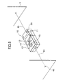
main body 11 has a rear pointer function. - The apparatus
main body 11 is designed to project a rearlaser pointer beam 61 from a rear end surface, and the rearlaser pointer beam 61 is on the same straight line as thedistance measuring light 30 which is projected in a front direction. The rear laser pointer beam projected in a backward direction is a visible laser beam. The rearlaser pointer beam 61 is used to align with areference point 62 at a rear position. When the rear position is determined, the measuring direction is also determined, and this further facilitates the measurement operation using thetarget unit 12. - Fig. 6 shows another embodiment of the present invention. In this embodiment, even when the apparatus
main body 11 is integrated with thetarget unit 12, signals are given and received between these two units via optical communication. - In the above embodiment, there is no need to use the
connector units - More concrete description will be given below.
- In Fig. 6, the
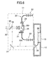
distance measuring unit 22 in the apparatusmain body 11 is shown in detail. - In the figure,
reference numeral 32 denotes a distance measuring light emitting unit, and a driver (not shown; see the light emittingside analog circuit 40 in Fig. 4) of the distance measuringlight emitting unit 32 is modulated by themodulation circuit 23. - The modulated distance measuring light is selectively divided to an
internal reference light 30r and thedistance measuring light 30 by achopper 29. Thedistance measuring light 30 is projected to a target object via aprism 35 and a half-mirror 36. Theinternal reference light 30r passes through theprism 35 and adensity filter 31 and enters a distance measuringlight receiving unit 33. A part of thedistance measuring light 30 is split by the half-mirror 36, and thesplit light 30b enters thephotodetection element 38 of thephotodetection unit 15 via themirror 37. From thephotodetection element 38, a photodetection signal is inputted to thetarget control unit 26. - A reflected distance measuring light 30' projected from the apparatus
main body 11 and reflected by the target object enters the apparatusmain body 11 again. It is further reflected by theprism 35 and enters the distance measuringlight receiving unit 33. Thedensity filter 31 turns light amount of theinternal reference light 30r and the reflected distance measuring light 30' to a constant level, and these beams enter the distance measuringlight receiving unit 33. Based on the reflected distance measuring light 30' entering the distance measuringlight receiving unit 33 and on theinternal reference light 30r, light wave distance measurement is performed. The result of measurement is polymerized to thedistance measuring light 30 by themodulation circuit 23 as communication data. - Distance measurement data is polymerized to the split light 30b, and the
target control unit 26 separates and extracts the distance measurement data from the photodetection signal from thephotodetection element 38. The distance measurement data thus separated and extracted is displayed on thetarget display unit 13 or it is stored in thedata storage unit 27. - The communication between the apparatus
main body 11 and thetarget unit 12 may be radio communication instead of optical communication. Or, another optical communication means for optical communication may be provided, which uses a different light from the distance measuring light. - According to the present invention, distance measurement can be achieved in a non-prism mode. Even when there is no suitable target object and distance measurement in a non-prism mode is difficult to perform, the target unit can be used as the target object. Thus, distance can be measured regardless of measuring environment. Because the target unit is provided with a reflection unit, reflection can be achieved with high efficiency. Distance measurement for a long distance can be performed. Using a distance measuring light as a guide light, a measuring point can be set as desired, or measuring points can be set with a given spacing.
Claims (10)
- A portable type distance measuring apparatus which comprises a apparatus main body having a distance measuring unit for measuring a distance by projecting a distance measuring light, a control unit for controlling said distance measuring unit and for processing measurement data from said distance measuring unit and a transmitting unit to emit a communication light including the measurement data to a distance measuring direction, and a target unit having a display unit, an operation unit and a photodetection unit for receiving the communication light, wherein said target unit is removably mounted on said apparatus main body so that said target unit may be used as an object to be measured for distance measurement when necessary.
- A portable type distance measuring apparatus according to claim 1, wherein said apparatus main body further comprises a display unit and an operation unit, and said apparatus main body can be operated under condition that said target unit is separated.
- A portable type distance measuring apparatus according to claim 1, wherein each of said apparatus main body and said target unit comprises a power source unit and a control unit so that said apparatus main body and said target unit can be operated independently.
- A portable type distance measuring apparatus according to claim 1, wherein the distance measuring light also serves as the communication light, said transmitting unit comprises a modulation circuit for polymerizing the measurement data to the distance measuring light, and said target unit comprises a demodulation circuit for separating and extracting the measurement data from the distance measuring light.
- A portable type distance measuring apparatus according to claim 1, wherein at least one of said apparatus main body and said target unit is provided with an arithmetic operation program for obtaining survey results as desired based on the distance measurement data.
- A portable type distance measuring apparatus according to claim 1, wherein said apparatus main body and said target unit are integrated with each other, and the distance measurement data is delivered and received between said apparatus main body and said target unit by the distance measuring light.
- A portable type distance measuring apparatus according to claim 1, wherein the distance measuring light is a visible light and has a pointer function.
- A portable type distance measuring apparatus according to claim 1, wherein a visible laser pointer beam is projected to a direction opposite to a projecting direction of the distance measuring light.
- A portable type distance measuring apparatus according to claim 1, wherein a bubble tube for detecting horizontality of the distance measuring light is provided on said apparatus main body.
- A portable type distance measuring apparatus according to claim 9, wherein said bubble tube is an electric bubble tube for detecting inclination, and a tilt angle is displayed on said display unit based on an output corresponding to the inclination.
Applications Claiming Priority (2)
| Application Number | Priority Date | Filing Date | Title |
|---|---|---|---|
| JP2000222351 | 2000-07-24 | ||
| JP2000222351A JP4614506B2 (en) | 2000-07-24 | 2000-07-24 | Portable distance measuring device |
Publications (3)
| Publication Number | Publication Date |
|---|---|
| EP1176429A2 true EP1176429A2 (en) | 2002-01-30 |
| EP1176429A3 EP1176429A3 (en) | 2003-03-26 |
| EP1176429B1 EP1176429B1 (en) | 2004-09-29 |
Family
ID=18716606
Family Applications (1)
| Application Number | Title | Priority Date | Filing Date |
|---|---|---|---|
| EP01116523A Expired - Lifetime EP1176429B1 (en) | 2000-07-24 | 2001-07-07 | Portable type distance measuring apparatus |
Country Status (4)
| Country | Link |
|---|---|
| US (1) | US6396571B2 (en) |
| EP (1) | EP1176429B1 (en) |
| JP (1) | JP4614506B2 (en) |
| DE (1) | DE60105918T2 (en) |
Cited By (6)
| Publication number | Priority date | Publication date | Assignee | Title |
|---|---|---|---|---|
| WO2004020941A1 (en) * | 2002-08-28 | 2004-03-11 | Robert Bosch Gmbh | Device and method for optical distance measurement |
| EP1566658A1 (en) * | 2004-02-19 | 2005-08-24 | Leica Geosystems AG | Handheld apparatus for measuring distances |
| WO2005088247A1 (en) * | 2004-03-13 | 2005-09-22 | Kapro Intelligent Tools Ltd | Distance measurement device |
| EP1503176A3 (en) * | 2003-07-23 | 2007-05-02 | Kabushiki Kaisha Topcon | Survey guiding system |
| US7804051B2 (en) | 2005-06-13 | 2010-09-28 | Leica Geosystems Ag | Geodetic target object and surveying system with a structural integration of transmitting channels and receiving channels into a common unit with a reflector component |
| EP3482157A4 (en) * | 2016-07-07 | 2020-04-22 | Hill, Jayson | Adjustable laser leveling device with distance measuring lasers and self-leveling lasers and related method |
Families Citing this family (53)
| Publication number | Priority date | Publication date | Assignee | Title |
|---|---|---|---|---|
| US8240077B2 (en) | 2002-03-04 | 2012-08-14 | Larry Holmberg | Range finder for weapons |
| US7643132B2 (en) * | 2002-03-04 | 2010-01-05 | Larry Holmberg | Range finder |
| US6615531B1 (en) * | 2002-03-04 | 2003-09-09 | Larry Holmberg | Range finder |
| US6556245B1 (en) | 1999-03-08 | 2003-04-29 | Larry Allan Holmberg | Game hunting video camera |
| US7574824B2 (en) | 2006-01-06 | 2009-08-18 | Larry Holmberg | Device mount for a firearm |
| US7110092B2 (en) * | 2000-08-01 | 2006-09-19 | Michael Kasper | Measuring device and measuring method for determining distance and/or position |
| US8156680B2 (en) | 2002-03-04 | 2012-04-17 | Larry Holmberg | Device mounting system for a weapon |
| DE10214742A1 (en) * | 2002-04-02 | 2003-10-16 | Hilti Ag | Hand-held optical lateral distance measuring device has second laser distance measurement module mechanically, data technically coupled to first, laser beams at defined angle relative to each other |
| DE10216207A1 (en) | 2002-04-12 | 2003-11-06 | Bosch Gmbh Robert | distance measuring |
| JP4121803B2 (en) * | 2002-08-08 | 2008-07-23 | 株式会社トプコン | Lightwave distance measuring device |
| DE10252743A1 (en) * | 2002-11-13 | 2004-05-27 | Hilti Ag | Manageable laser distance measuring device |
| JP2004205221A (en) * | 2002-12-20 | 2004-07-22 | Matsushita Electric Works Ltd | Portable distance measuring apparatus |
| US7479624B2 (en) * | 2003-07-30 | 2009-01-20 | Glenn Morris | Laser light actuation system |
| US20060028351A1 (en) * | 2004-08-09 | 2006-02-09 | Lewis James M | Docking monitor |
| DE102004053686A1 (en) * | 2004-11-03 | 2006-05-04 | Essling, Mirko | Laser receiving device with improved accuracy and lower power consumption |
| JP4745675B2 (en) * | 2005-02-04 | 2011-08-10 | 株式会社 ソキア・トプコン | Surveyor remote control device |
| JP4977339B2 (en) * | 2005-07-11 | 2012-07-18 | 株式会社トプコン | Geographic data collection device |
| US7933001B2 (en) | 2005-07-11 | 2011-04-26 | Kabushiki Kaisha Topcon | Geographic data collecting system |
| JP4944462B2 (en) * | 2006-03-14 | 2012-05-30 | 株式会社トプコン | Geographic data collection device |
| US7787134B2 (en) * | 2005-11-09 | 2010-08-31 | The Boeing Company | Multiple fanned laser beam metrology system |
| US20080001057A1 (en) * | 2006-06-30 | 2008-01-03 | Larry Holmberg | Device mount |
| US7647922B2 (en) * | 2006-06-30 | 2010-01-19 | Larry Holmberg | Adaptor for device mount |
| US7506643B2 (en) * | 2006-06-30 | 2009-03-24 | Larry Holmberg | Crossbow device mount |
| WO2008008210A2 (en) * | 2006-07-12 | 2008-01-17 | Apache Technologies, Inc. | Handheld laser light detector with height correction, using a gps receiver to provide two-dimensional position data |
| US7594352B2 (en) * | 2006-10-17 | 2009-09-29 | Larry Holmberg | Device mount with stabilizing function |
| US7891131B2 (en) | 2007-01-05 | 2011-02-22 | Larry Holmberg | Device mount system for a weapon |
| US7739822B1 (en) | 2007-01-09 | 2010-06-22 | Larry Holmberg | Method and device for mounting an accessory to a firearm |
| JP2008281379A (en) * | 2007-05-09 | 2008-11-20 | Sokkia Topcon Co Ltd | Portable distance measuring device |
| JP2009109204A (en) * | 2007-10-26 | 2009-05-21 | Nippon Paper Industries Co Ltd | Blade surface clearance measuring device of disk refiner |
| US7780363B1 (en) | 2008-01-17 | 2010-08-24 | Larry Holmberg | Device for mounting imaging equipment to a bow and method of recording a hunt |
| JP5150307B2 (en) | 2008-03-03 | 2013-02-20 | 株式会社トプコン | Geographic data collection device |
| JP5150310B2 (en) | 2008-03-04 | 2013-02-20 | 株式会社トプコン | Geographic data collection device |
| US8258453B2 (en) * | 2009-04-29 | 2012-09-04 | Intersil Americas Inc. | Long range proximity and/or motion detector with ambient light detection capabilities |
| US8161674B2 (en) * | 2009-06-16 | 2012-04-24 | Larry Holmberg | Electronic device mount system with strap |
| US8024884B2 (en) | 2009-06-16 | 2011-09-27 | Larry Holmberg | Electronic device mount system for weapons |
| JP5693827B2 (en) * | 2009-06-17 | 2015-04-01 | 株式会社トプコン | Surveying system |
| DE102009027966A1 (en) * | 2009-07-23 | 2011-02-03 | Räuber, Roland | Sprit level e.g. water level, for marking mounting points at workpiece i.e.wall, has marking device for marking mounting points, and controller with keyboard for inputting data for points and connected with device for activating device |
| JP5698480B2 (en) | 2010-09-02 | 2015-04-08 | 株式会社トプコン | Measuring method and measuring device |
| JP5690541B2 (en) * | 2010-09-30 | 2015-03-25 | 株式会社トプコン | Distance measuring device |
| US8656624B2 (en) | 2010-12-29 | 2014-02-25 | Larry Holmberg | Universal device mount |
| US8656625B2 (en) | 2010-12-29 | 2014-02-25 | Larry Holmberg | Accessory mount |
| US9222771B2 (en) | 2011-10-17 | 2015-12-29 | Kla-Tencor Corp. | Acquisition of information for a construction site |
| DE102013208164B4 (en) * | 2013-05-03 | 2019-05-23 | Robert Bosch Gmbh | Distance measuring Equipment |
| CN103675830A (en) * | 2013-12-09 | 2014-03-26 | 苏州市峰之火数码科技有限公司 | Outdoor distance measurement glasses |
| CN104165622A (en) * | 2014-06-19 | 2014-11-26 | 苏州一光仪器有限公司 | Total station and setting-out survey device |
| JP6533691B2 (en) * | 2015-04-28 | 2019-06-19 | 株式会社トプコン | Three-dimensional position measurement system |
| JP6533690B2 (en) * | 2015-04-28 | 2019-06-19 | 株式会社トプコン | Three-dimensional position measurement system |
| CN107044851A (en) * | 2016-02-06 | 2017-08-15 | 常州华达科捷光电仪器有限公司 | A kind of laser level rule |
| DE102016104801A1 (en) * | 2016-03-15 | 2017-09-21 | Windmöller & Hölscher Kg | Auxiliary device for aligning a winding tube and method for aligning a winding tube |
| KR101782509B1 (en) * | 2016-04-11 | 2017-09-27 | 에스티씨테크 (주) | A Device for Measuring a Length Using Ultrasound |
| JP6748908B2 (en) * | 2016-05-24 | 2020-09-02 | 清水建設株式会社 | Intelligent reflective target |
| JP2020201092A (en) * | 2019-06-07 | 2020-12-17 | 株式会社ニコンビジョン | Display device, distance measurement device, and display method |
| US12152882B2 (en) * | 2020-12-01 | 2024-11-26 | Milwaukee Electric Tool Corporation | Laser level systems and controls |
Citations (4)
| Publication number | Priority date | Publication date | Assignee | Title |
|---|---|---|---|---|
| US4560270A (en) * | 1981-08-07 | 1985-12-24 | Geotronics Ab | Device included in a distance meter system |
| US4681433A (en) * | 1978-07-20 | 1987-07-21 | Kern & Co. Ag. | Method and apparatus for measuring relative position |
| EP0269276A2 (en) * | 1986-10-29 | 1988-06-01 | Winlam Company | Hand-held measuring device |
| EP0716288A1 (en) * | 1994-12-09 | 1996-06-12 | Kabushiki Kaisha Topcon | Surveying instrument |
Family Cites Families (15)
| Publication number | Priority date | Publication date | Assignee | Title |
|---|---|---|---|---|
| US3865491A (en) * | 1971-09-20 | 1975-02-11 | Blount & George Inc | Surveying instrument tracking system |
| CH599536A5 (en) * | 1975-09-02 | 1978-05-31 | Kern & Co Ag | |
| JPS57119274A (en) * | 1981-01-19 | 1982-07-24 | Nippon Kokan Kk <Nkk> | Light wave range finder |
| US4820041A (en) * | 1986-11-12 | 1989-04-11 | Agtek Development Co., Inc. | Position sensing system for surveying and grading |
| DE3703422A1 (en) * | 1987-02-05 | 1988-08-18 | Zeiss Carl Fa | OPTOELECTRONIC DISTANCE SENSOR |
| GB8908375D0 (en) * | 1989-04-13 | 1989-06-01 | Measurement Devices Ltd | Hand-held laser rangefinder |
| JP3226970B2 (en) * | 1992-07-09 | 2001-11-12 | 株式会社トプコン | Laser surveying machine |
| JPH06185991A (en) * | 1992-12-15 | 1994-07-08 | Minolta Camera Co Ltd | Measuring instrument |
| DE4316348A1 (en) | 1993-05-15 | 1994-11-17 | Wild Heerbrugg Ag | Distance measuring device |
| JPH0777424A (en) * | 1993-09-07 | 1995-03-20 | Wacom Co Ltd | Optical surveying instrument |
| JPH08278131A (en) * | 1995-04-10 | 1996-10-22 | Nikon Corp | Three-dimensional measurement and installation system |
| JPH09211127A (en) * | 1996-02-02 | 1997-08-15 | Nikon Corp | Distance measuring device |
| JP3741477B2 (en) * | 1996-03-18 | 2006-02-01 | 株式会社トプコン | Surveying system |
| JPH10170265A (en) * | 1996-12-09 | 1998-06-26 | Fuji Photo Optical Co Ltd | Position measuring/drawing device capable of measurement control from measuring point instruction part |
| JPH11122179A (en) * | 1997-10-09 | 1999-04-30 | Seiko Epson Corp | Spatial light transmission device and space light transmission method |
-
2000
- 2000-07-24 JP JP2000222351A patent/JP4614506B2/en not_active Expired - Fee Related
-
2001
- 2001-06-18 US US09/883,637 patent/US6396571B2/en not_active Expired - Lifetime
- 2001-07-07 EP EP01116523A patent/EP1176429B1/en not_active Expired - Lifetime
- 2001-07-07 DE DE60105918T patent/DE60105918T2/en not_active Expired - Lifetime
Patent Citations (4)
| Publication number | Priority date | Publication date | Assignee | Title |
|---|---|---|---|---|
| US4681433A (en) * | 1978-07-20 | 1987-07-21 | Kern & Co. Ag. | Method and apparatus for measuring relative position |
| US4560270A (en) * | 1981-08-07 | 1985-12-24 | Geotronics Ab | Device included in a distance meter system |
| EP0269276A2 (en) * | 1986-10-29 | 1988-06-01 | Winlam Company | Hand-held measuring device |
| EP0716288A1 (en) * | 1994-12-09 | 1996-06-12 | Kabushiki Kaisha Topcon | Surveying instrument |
Cited By (7)
| Publication number | Priority date | Publication date | Assignee | Title |
|---|---|---|---|---|
| WO2004020941A1 (en) * | 2002-08-28 | 2004-03-11 | Robert Bosch Gmbh | Device and method for optical distance measurement |
| EP1503176A3 (en) * | 2003-07-23 | 2007-05-02 | Kabushiki Kaisha Topcon | Survey guiding system |
| EP1566658A1 (en) * | 2004-02-19 | 2005-08-24 | Leica Geosystems AG | Handheld apparatus for measuring distances |
| WO2005088247A1 (en) * | 2004-03-13 | 2005-09-22 | Kapro Intelligent Tools Ltd | Distance measurement device |
| US7804051B2 (en) | 2005-06-13 | 2010-09-28 | Leica Geosystems Ag | Geodetic target object and surveying system with a structural integration of transmitting channels and receiving channels into a common unit with a reflector component |
| EP3482157A4 (en) * | 2016-07-07 | 2020-04-22 | Hill, Jayson | Adjustable laser leveling device with distance measuring lasers and self-leveling lasers and related method |
| US11994389B2 (en) | 2016-07-07 | 2024-05-28 | Sure Hang, Llc | Adjustable laser leveling device with distance measuring lasers and self-leveling lasers and related method |
Also Published As
| Publication number | Publication date |
|---|---|
| DE60105918D1 (en) | 2004-11-04 |
| US20020008866A1 (en) | 2002-01-24 |
| EP1176429B1 (en) | 2004-09-29 |
| US6396571B2 (en) | 2002-05-28 |
| JP2002039748A (en) | 2002-02-06 |
| DE60105918T2 (en) | 2006-03-09 |
| JP4614506B2 (en) | 2011-01-19 |
| EP1176429A3 (en) | 2003-03-26 |
Similar Documents
| Publication | Publication Date | Title |
|---|---|---|
| EP1176429B1 (en) | Portable type distance measuring apparatus | |
| JP3268608B2 (en) | Surveying equipment | |
| EP1503176B1 (en) | Survey guiding system | |
| EP0716288B2 (en) | Surveying instrument | |
| US11822351B2 (en) | Three-dimensional information processing unit, apparatus having three-dimensional information processing unit, unmanned aerial vehicle, informing device, method and program for controlling mobile body using three-dimensional information processing unit | |
| US6894767B2 (en) | Light wave distance-measuring system | |
| CN101490505B (en) | Handheld laser light detector with height correction, using a GPS receiver to provide two-dimensional position data | |
| JP4210792B2 (en) | Position detection device | |
| EP0047243B1 (en) | Method and apparatus for determining position | |
| JPH09250927A (en) | Surveying system | |
| JPH04504755A (en) | handheld laser rangefinder | |
| EP1030163A2 (en) | reflective prism device | |
| US7304727B2 (en) | Laser distance-measuring device | |
| US8681318B2 (en) | Distance measuring device | |
| AU2022202409B2 (en) | Distance detector | |
| JP3270168B2 (en) | Surveying equipment | |
| JP2511413B2 (en) | Surveying equipment | |
| JPH05323029A (en) | Distance measuring method by light wave range finder | |
| JP2003021514A (en) | Machine height measuring device for surveying machine and surveying machine using it and machine height measuring method for surveying machine | |
| JP2511414B2 (en) | Surveying equipment | |
| JP4358952B2 (en) | Surveying instrument and surveying method | |
| JPH10197247A (en) | Automatic tracking apparatus for position measuring plotter | |
| EP4261500A1 (en) | Surveying instrument | |
| JPH0119047Y2 (en) | ||
| JPH09101150A (en) | Point setting radar device |
Legal Events
| Date | Code | Title | Description |
|---|---|---|---|
| PUAI | Public reference made under article 153(3) epc to a published international application that has entered the european phase |
Free format text: ORIGINAL CODE: 0009012 |
|
| AK | Designated contracting states |
Kind code of ref document: A2 Designated state(s): AT BE CH CY DE DK ES FI FR GB GR IE IT LI LU MC NL PT SE TR |
|
| AX | Request for extension of the european patent |
Free format text: AL;LT;LV;MK;RO;SI |
|
| PUAL | Search report despatched |
Free format text: ORIGINAL CODE: 0009013 |
|
| AK | Designated contracting states |
Kind code of ref document: A3 Designated state(s): AT BE CH CY DE DK ES FI FR GB GR IE IT LI LU MC NL PT SE TR Designated state(s): AT BE CH CY DE DK ES FI FR GB GR IE IT LI LU MC NL PT SE TR |
|
| AX | Request for extension of the european patent |
Extension state: AL LT LV MK RO SI |
|
| RIC1 | Information provided on ipc code assigned before grant |
Ipc: 7G 01C 3/08 B Ipc: 7G 01C 15/00 B Ipc: 7G 01S 7/481 B Ipc: 7G 01S 7/497 B Ipc: 7G 01S 17/36 B Ipc: 7G 01S 17/06 A |
|
| 17P | Request for examination filed |
Effective date: 20030808 |
|
| AKX | Designation fees paid |
Designated state(s): CH DE LI SE |
|
| GRAP | Despatch of communication of intention to grant a patent |
Free format text: ORIGINAL CODE: EPIDOSNIGR1 |
|
| GRAS | Grant fee paid |
Free format text: ORIGINAL CODE: EPIDOSNIGR3 |
|
| GRAA | (expected) grant |
Free format text: ORIGINAL CODE: 0009210 |
|
| AK | Designated contracting states |
Kind code of ref document: B1 Designated state(s): CH DE LI SE |
|
| REG | Reference to a national code |
Ref country code: CH Ref legal event code: EP |
|
| REG | Reference to a national code |
Ref country code: IE Ref legal event code: FG4D |
|
| REF | Corresponds to: |
Ref document number: 60105918 Country of ref document: DE Date of ref document: 20041104 Kind code of ref document: P |
|
| REG | Reference to a national code |
Ref country code: CH Ref legal event code: NV Representative=s name: FIAMMENGHI-FIAMMENGHI |
|
| REG | Reference to a national code |
Ref country code: SE Ref legal event code: TRGR |
|
| PLBE | No opposition filed within time limit |
Free format text: ORIGINAL CODE: 0009261 |
|
| STAA | Information on the status of an ep patent application or granted ep patent |
Free format text: STATUS: NO OPPOSITION FILED WITHIN TIME LIMIT |
|
| 26N | No opposition filed |
Effective date: 20050630 |
|
| PGFP | Annual fee paid to national office [announced via postgrant information from national office to epo] |
Ref country code: CH Payment date: 20100714 Year of fee payment: 10 |
|
| PGFP | Annual fee paid to national office [announced via postgrant information from national office to epo] |
Ref country code: SE Payment date: 20100708 Year of fee payment: 10 Ref country code: DE Payment date: 20100630 Year of fee payment: 10 |
|
| REG | Reference to a national code |
Ref country code: CH Ref legal event code: PL |
|
| REG | Reference to a national code |
Ref country code: SE Ref legal event code: EUG |
|
| PG25 | Lapsed in a contracting state [announced via postgrant information from national office to epo] |
Ref country code: CH Free format text: LAPSE BECAUSE OF NON-PAYMENT OF DUE FEES Effective date: 20110731 Ref country code: LI Free format text: LAPSE BECAUSE OF NON-PAYMENT OF DUE FEES Effective date: 20110731 Ref country code: DE Free format text: LAPSE BECAUSE OF NON-PAYMENT OF DUE FEES Effective date: 20120201 |
|
| REG | Reference to a national code |
Ref country code: DE Ref legal event code: R119 Ref document number: 60105918 Country of ref document: DE Effective date: 20120201 |
|
| PG25 | Lapsed in a contracting state [announced via postgrant information from national office to epo] |
Ref country code: SE Free format text: LAPSE BECAUSE OF NON-PAYMENT OF DUE FEES Effective date: 20110708 |