EP1176339A2 - Torque fluctuation absorbing apparatus having structure for reducing misalignment of torque limiter during assembling thereof, and method for assembling the same - Google Patents
Torque fluctuation absorbing apparatus having structure for reducing misalignment of torque limiter during assembling thereof, and method for assembling the same Download PDFInfo
- Publication number
- EP1176339A2 EP1176339A2 EP01118124A EP01118124A EP1176339A2 EP 1176339 A2 EP1176339 A2 EP 1176339A2 EP 01118124 A EP01118124 A EP 01118124A EP 01118124 A EP01118124 A EP 01118124A EP 1176339 A2 EP1176339 A2 EP 1176339A2
- Authority
- EP
- European Patent Office
- Prior art keywords
- flywheel
- torque
- damper
- torque limiter
- driven
- Prior art date
- Legal status (The legal status is an assumption and is not a legal conclusion. Google has not performed a legal analysis and makes no representation as to the accuracy of the status listed.)
- Granted
Links
Images






Classifications
-
- F—MECHANICAL ENGINEERING; LIGHTING; HEATING; WEAPONS; BLASTING
- F16—ENGINEERING ELEMENTS AND UNITS; GENERAL MEASURES FOR PRODUCING AND MAINTAINING EFFECTIVE FUNCTIONING OF MACHINES OR INSTALLATIONS; THERMAL INSULATION IN GENERAL
- F16F—SPRINGS; SHOCK-ABSORBERS; MEANS FOR DAMPING VIBRATION
- F16F15/00—Suppression of vibrations in systems; Means or arrangements for avoiding or reducing out-of-balance forces, e.g. due to motion
- F16F15/10—Suppression of vibrations in rotating systems by making use of members moving with the system
- F16F15/12—Suppression of vibrations in rotating systems by making use of members moving with the system using elastic members or friction-damping members, e.g. between a rotating shaft and a gyratory mass mounted thereon
- F16F15/131—Suppression of vibrations in rotating systems by making use of members moving with the system using elastic members or friction-damping members, e.g. between a rotating shaft and a gyratory mass mounted thereon the rotating system comprising two or more gyratory masses
- F16F15/13164—Suppression of vibrations in rotating systems by making use of members moving with the system using elastic members or friction-damping members, e.g. between a rotating shaft and a gyratory mass mounted thereon the rotating system comprising two or more gyratory masses characterised by the supporting arrangement of the damper unit
-
- F—MECHANICAL ENGINEERING; LIGHTING; HEATING; WEAPONS; BLASTING
- F16—ENGINEERING ELEMENTS AND UNITS; GENERAL MEASURES FOR PRODUCING AND MAINTAINING EFFECTIVE FUNCTIONING OF MACHINES OR INSTALLATIONS; THERMAL INSULATION IN GENERAL
- F16D—COUPLINGS FOR TRANSMITTING ROTATION; CLUTCHES; BRAKES
- F16D7/00—Slip couplings, e.g. slipping on overload, for absorbing shock
- F16D7/02—Slip couplings, e.g. slipping on overload, for absorbing shock of the friction type
- F16D7/024—Slip couplings, e.g. slipping on overload, for absorbing shock of the friction type with axially applied torque limiting friction surfaces
- F16D7/025—Slip couplings, e.g. slipping on overload, for absorbing shock of the friction type with axially applied torque limiting friction surfaces with flat clutching surfaces, e.g. discs
-
- F—MECHANICAL ENGINEERING; LIGHTING; HEATING; WEAPONS; BLASTING
- F16—ENGINEERING ELEMENTS AND UNITS; GENERAL MEASURES FOR PRODUCING AND MAINTAINING EFFECTIVE FUNCTIONING OF MACHINES OR INSTALLATIONS; THERMAL INSULATION IN GENERAL
- F16F—SPRINGS; SHOCK-ABSORBERS; MEANS FOR DAMPING VIBRATION
- F16F15/00—Suppression of vibrations in systems; Means or arrangements for avoiding or reducing out-of-balance forces, e.g. due to motion
- F16F15/10—Suppression of vibrations in rotating systems by making use of members moving with the system
- F16F15/12—Suppression of vibrations in rotating systems by making use of members moving with the system using elastic members or friction-damping members, e.g. between a rotating shaft and a gyratory mass mounted thereon
- F16F15/1203—Suppression of vibrations in rotating systems by making use of members moving with the system using elastic members or friction-damping members, e.g. between a rotating shaft and a gyratory mass mounted thereon characterised by manufacturing, e.g. assembling or testing procedures for the damper units
-
- F—MECHANICAL ENGINEERING; LIGHTING; HEATING; WEAPONS; BLASTING
- F16—ENGINEERING ELEMENTS AND UNITS; GENERAL MEASURES FOR PRODUCING AND MAINTAINING EFFECTIVE FUNCTIONING OF MACHINES OR INSTALLATIONS; THERMAL INSULATION IN GENERAL
- F16F—SPRINGS; SHOCK-ABSORBERS; MEANS FOR DAMPING VIBRATION
- F16F15/00—Suppression of vibrations in systems; Means or arrangements for avoiding or reducing out-of-balance forces, e.g. due to motion
- F16F15/10—Suppression of vibrations in rotating systems by making use of members moving with the system
- F16F15/12—Suppression of vibrations in rotating systems by making use of members moving with the system using elastic members or friction-damping members, e.g. between a rotating shaft and a gyratory mass mounted thereon
- F16F15/1207—Suppression of vibrations in rotating systems by making use of members moving with the system using elastic members or friction-damping members, e.g. between a rotating shaft and a gyratory mass mounted thereon characterised by the supporting arrangement of the damper unit
-
- F—MECHANICAL ENGINEERING; LIGHTING; HEATING; WEAPONS; BLASTING
- F16—ENGINEERING ELEMENTS AND UNITS; GENERAL MEASURES FOR PRODUCING AND MAINTAINING EFFECTIVE FUNCTIONING OF MACHINES OR INSTALLATIONS; THERMAL INSULATION IN GENERAL
- F16F—SPRINGS; SHOCK-ABSORBERS; MEANS FOR DAMPING VIBRATION
- F16F15/00—Suppression of vibrations in systems; Means or arrangements for avoiding or reducing out-of-balance forces, e.g. due to motion
- F16F15/10—Suppression of vibrations in rotating systems by making use of members moving with the system
- F16F15/12—Suppression of vibrations in rotating systems by making use of members moving with the system using elastic members or friction-damping members, e.g. between a rotating shaft and a gyratory mass mounted thereon
- F16F15/129—Suppression of vibrations in rotating systems by making use of members moving with the system using elastic members or friction-damping members, e.g. between a rotating shaft and a gyratory mass mounted thereon characterised by friction-damping means
- F16F15/1297—Overload protection, i.e. means for limiting torque
-
- F—MECHANICAL ENGINEERING; LIGHTING; HEATING; WEAPONS; BLASTING
- F16—ENGINEERING ELEMENTS AND UNITS; GENERAL MEASURES FOR PRODUCING AND MAINTAINING EFFECTIVE FUNCTIONING OF MACHINES OR INSTALLATIONS; THERMAL INSULATION IN GENERAL
- F16F—SPRINGS; SHOCK-ABSORBERS; MEANS FOR DAMPING VIBRATION
- F16F15/00—Suppression of vibrations in systems; Means or arrangements for avoiding or reducing out-of-balance forces, e.g. due to motion
- F16F15/10—Suppression of vibrations in rotating systems by making use of members moving with the system
- F16F15/12—Suppression of vibrations in rotating systems by making use of members moving with the system using elastic members or friction-damping members, e.g. between a rotating shaft and a gyratory mass mounted thereon
- F16F15/131—Suppression of vibrations in rotating systems by making use of members moving with the system using elastic members or friction-damping members, e.g. between a rotating shaft and a gyratory mass mounted thereon the rotating system comprising two or more gyratory masses
- F16F15/13142—Suppression of vibrations in rotating systems by making use of members moving with the system using elastic members or friction-damping members, e.g. between a rotating shaft and a gyratory mass mounted thereon the rotating system comprising two or more gyratory masses characterised by the method of assembly, production or treatment
-
- F—MECHANICAL ENGINEERING; LIGHTING; HEATING; WEAPONS; BLASTING
- F16—ENGINEERING ELEMENTS AND UNITS; GENERAL MEASURES FOR PRODUCING AND MAINTAINING EFFECTIVE FUNCTIONING OF MACHINES OR INSTALLATIONS; THERMAL INSULATION IN GENERAL
- F16F—SPRINGS; SHOCK-ABSORBERS; MEANS FOR DAMPING VIBRATION
- F16F15/00—Suppression of vibrations in systems; Means or arrangements for avoiding or reducing out-of-balance forces, e.g. due to motion
- F16F15/10—Suppression of vibrations in rotating systems by making use of members moving with the system
- F16F15/12—Suppression of vibrations in rotating systems by making use of members moving with the system using elastic members or friction-damping members, e.g. between a rotating shaft and a gyratory mass mounted thereon
- F16F15/131—Suppression of vibrations in rotating systems by making use of members moving with the system using elastic members or friction-damping members, e.g. between a rotating shaft and a gyratory mass mounted thereon the rotating system comprising two or more gyratory masses
- F16F15/139—Suppression of vibrations in rotating systems by making use of members moving with the system using elastic members or friction-damping members, e.g. between a rotating shaft and a gyratory mass mounted thereon the rotating system comprising two or more gyratory masses characterised by friction-damping means
- F16F15/1397—Overload protection, i.e. means for limiting torque
Definitions
- the invention relates to a torque fluctuation absorbing apparatus having a structure for reducing misalignment of a torque limiter during assembling of the apparatus, and also relates to a method for assembling the torque fluctuation absorbing apparatus while reducing misalignment of the torque limiter when it is mounted in the apparatus.
- a torque fluctuation absorbing apparatus is coupled to and between an engine crankshaft and an input shaft of a driven-side assembly (e.g., a transmission of a hybrid vehicle which houses a motor) so as to reduce engine torque fluctuations.
- a driven-side assembly e.g., a transmission of a hybrid vehicle which houses a motor
- the torque fluctuation absorbing apparatus 1 includes a flywheel 10 coupled to a crankshaft 2 of an engine, a damper assembly 20 disposed in a torque transmission path between the flywheel 10 and a driven-side input shaft 3, and a torque limiter 30 disposed in a torque transmission path between the flywheel 10 and the damper assembly 20.
- the damper assembly 20 has a pair of drive plates 21, a driven plate 22, and spring dampers 24.
- the torque limiter 30 has a pair of linings 31 and a damper cover 32, and is adapted to slip when receiving a predetermined or larger amount of torque.
- the pair of linings 31 are secured to both faces of an outer peripheral portion of one of the drive plates 21 (or a member fixed to the drive plate 21).
- the pair of linings 31 are sandwiched between the damper cover 32 and the flywheel 10.
- slippage occurs on surfaces of the linings 31 that are in contact with the damper cover 32 and the flywheel 10.
- the drive plates 21 and the driven plate 22 are rotatable relative to each other in a circumferential direction thereof.
- a radial clearance d is provided between an outer periphery of the drive plate 21 (or a member secured thereto) and an inner periphery of the flywheel 10.
- Aprocedure of assembling the known torque fluctuation absorbing apparatus 1 is as follows: (1) a hub 22a of the driven plate 22 of the damper assembly 20 and the crankshaft 2 are aligned with an engine assembly by using a jig 50, as shown in Fig. 10, (2) the damper cover 32 is bolted to the flywheel 10, and the damper cover 32 and the flywheel 10 sandwich the linings 31 secured to the drive plate 21 to thereby support the damper assembly 20, and (3) the engine assembly is assembled with a driven-side assembly, and these assemblies are thus fixed to each other.
- the known apparatus however, has following problems.
- the drive plate may be disposed ecccentrically within the range of the clearance with respect to the flywheel, even with the driven plate being properly aligned with the engine assembly by using the jig upon assembling of the torque fluctuation absorbing apparatus with the engine assembly.
- the linings of the torque limiter secured to the drive plate may be out of alignment with respect to the flywheel in the radial directions. If the torque limiter is assembled eccentrically with the engine assembly, the following and/or other problems may occur when the engine is rotated, after assembling of the engine assembly with the driven-side assembly, to an angular point where the radial clearance between the drive plate and the driven plate disappears.
- the rotation of the input shaft of the driven-side assembly may become unstable or fluctuating due to the eccentric arrangement of the drive and driven plates, and torsional stress may be applied to a bearing 60 that supports the input shaft of the driven-side assembly, resulting in a reduction in the service life of the bearing 60, 2) the service life of a bushing 61 (or a needle bearing) that is in sliding contact with the driven-side input shaft during rotation thereof may be shortened, and 3) the performance of an oil seal 62 that is in sliding contact with the driven-side input shaft may deteriorate.
- a torque fluctuation absorbing apparatus provided between a crankshaft of an engine and a driven-side input shaft, comprising: (1) a flywheel coupled to the crankshaft, (2) a damper assembly disposed in a torque transmission path between the flywheel and the driven-side input shaft, the damper assembly including a pair of drive plates, a driven plate and at least one spring damper, and (3) a torque limiter disposed in a torque transmission path between the flywheel and the damper assembly, the torque limiter including a pair of linings that are adapted to slip when receiving at least a predetermined amount of torque.
- the torque limiter further includes a lining support plate to which the linings are fixed, and the linings are interposed between the pair of the drive plates.
- the drive plates and the linings are centered with each other and assembled into a damper-torque limiter assembly, while the lining support plate is centered with respect to the flywheel, such that the damper-torque limiter assembly is fixed at the lining support plate to the flywheel.
- the drive plates, the linings, and the flywheel are brought into concentric relationship with each other, thus effectively preventing the torque limiter from being eccentrically positioned with respect to the engine assembly during assembling of the apparatus.
- a torque fluctuation absorbing apparatus including the flywheel, the damper assembly and the torque limiter as described above, in which the linings of the torque limiter are fixed to one of the drive plates of the damper assembly, and the torque limiter includes a pair of damper covers between which the linings are interposed.
- the drive plates and the damper covers are centered with each other and assembled into a damper-torque limiter assembly, while the damper covers are centered with respect to the flywheel, such that the damper-torque limiter assembly is fixed at the damper covers to the flywheel.
- a torque fluctuation absorbing apparatus including the flywheel, the damper assembly and the torque limiter as described above, in which the linings of the torque limiter are fixed to one of the drive plates, and the linings are interposed between the flywheel and a damper cover that forms a part of the torque limiter, while the flywheel includes a flywheel main body and a flywheel plate that are fastened to each other.
- the drive plates, the linings and the damper cover are centered with respect to the flywheel main body, and are assembled together to provide an assembly of the flywheel main body, the damper assembly and the torque limiter. After the engine is assembled with the drive-side input shaft, the assembly of the flywheel main body, the damper assembly and the torque limiter is fastened to the flywheel plate that is fixed to the crankshaft.
- a torque fluctuation absorbing apparatus including the flywheel, the damper assembly and the torque limiter as described above, in which the driven-side input shaft includes an axially protruding portion at a distal end thereof, and the crankshaft has a recess formed in a distal end portion thereof, and a bearing that is fitted in the recess. Furthermore, the axially protruding portion is received in an inner bore of the bearing, and an elastic material is provided between the bearing and the crankshaft or between the bearing and the axially protruding portion.
- a torque fluctuation absorbing apparatus including the flywheel, the damper assembly and the torque limiter as described above, and further including a bearing that is fitted in a recess formed in a distal end portion of the crankshaft, and a drive plate support member that supports the drive plates.
- One end of the drive plate support member is fitted in an inner circumferential wall of the bearing, and the other end of the drive plate support member is fixed to one of the drive plates.
- a torque fluctuation absorbing apparatus including the flywheel, the damper assembly and the torque limiter as described above, and further including a bearing that is fitted in a recess formed in a distal end portion of the crankshaft, and a driven plate support member that supports the driven plate.
- a bearing that is fitted in a recess formed in a distal end portion of the crankshaft
- a driven plate support member that supports the driven plate.
- One end of the driven plate support member is fitted in an inner circumferential wall of the bearing, and the other end of the support member is fixed to the driven plate.
- a method of assembling a torque fluctuation absorbing apparatus including the flywheel, the damper assembly, and the torque limiter as described above, which method includes steps of (1) temporarily centering the drive plates to which the linings are fixed and the driven plate with each other (by using a pin), and (2) centering the damper assembly in which the drive plates and the driven plate are centered with each other, with respect to the flywheel, (by using a jig), and fixing the damper assembly to the flywheel via a damper cover that forms a part of the torque limiter.
- a method of assembling a torque fluctuation absorbing apparatus including the flywheel, the damper assembly, and the torque limiter as described above, which method includes steps of (1)centering the drive plates to which the linings are fixed, with respect to the flywheel(, by using a jig), and (2) fixing the damper assembly that is centered with respect to the flywheel, to the flywheel, by a damper cover that forms a part of the torque limiter.
- a method of assembling a torque fluctuation absorbing apparatus including the flywheel, the damper assembly, and the torque limiter as described above, which method includes steps of (1) engaging the engine with the driven-side input shaft, and (2) then forcing the torque fluctuation absorbing apparatus to resonate under control, so as to cause the torque limiter to slip, thereby reducing misalignment of the torque limiter during assembling of the torque fluctuation absorbing apparatus.
- a method of assembling a torque fluctuation absorbing apparatus including the flywheel, the damper assembly, and the torque limiter as described above, which method includes steps of: (1) engaging the engine with the driven-side input shaft, and (2) then temporarily reducing an amount of torque that is required for causing slippage of the torque limiter, so as to permit the torque limiter to slip, thereby reducing misalignment of the torque limiter during assembling of the torque fluctuaion absorbing apparatus.
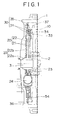
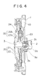
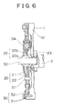
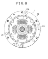
- FIG. 1 through Fig. 8 there will be described a structure and a method for reducing or preventing misalignment of a torque limiter during assembling of a torque fluctuation absorbing apparatus according to preferred embodiments of the invention.
- Fig. 1 through Fig. 8 the same or similar elements or portions that are common to all of the embodiments are denoted by the same reference numerals.
- the same reference numerals as used in Fig. 9 and Fig. 10 showing the known arrangement are used to identify structurally corresponding elements or portions in Fig. 1 through Fig. 8.
- the torque fluctuation absorbing apparatus is adapted to transmit torque from an engine crankshaft 2 to a driven-side input shaft 3.
- the apparatus 1 includes a flywheel 10 that is coupled to the engine crankshaft 2, and a driven plate 22 having a hub portion 22a that is in splined engagement with the driven-side input shaft 3.
- the driven-side assembly may be, for example, a transmission (T/M) of a hybrid vehicle that is driven with an engine and an electric motor.
- the transmission (T/M) includes the input shaft 3, an electric motor coupled through a planetary gear set to the input shaft 3, a charging generator, bearings 60 that rotatably support the input shaft 3, a bush 61 (or a needle bearing), a T/M casing 63, an oil seal 62 that seals the input shaft 3 and the T/M casing 63, and other components.
- the torque fluctuation absorbing apparatus 1 to which the method or structure for reducing misalignment of the torque limiter according to the invention is applied, includes a flywheel 10 that is coupled to the engine crankshaft 2, a damper assembly 20 disposed in a torque transmission path between the flywheel 10 and the driven-side input shaft 3, and a torque limiter 30 disposed in a torque transmission path between the flywheel 10 and the damper assembly 20.
- the damper assembly 20 has a pair of drive plates 21, a driven plate 22, and spring dampers 24.
- the torque limiter 30 has a pair of lining portions 31 (or at least one lining portion 31), and gives rise to slippage when receiving torque of a predetermined value or larger.
- the flywheel 10 may be formed as an integral body, or may be a structure in which a flywheel main body 11 is fastened to a flywheel plate 12 with a bolt 13, as shown in Fig. 3.
- the flywheel 10 functions as a mass in a vibration system.
- the pair of drive plates 21 and the driven plate 22 are rotatable relative to each other.
- the pair of drive plates 21 have a plurality of windows that extend in the circumferential direction, and the spring damper 24 is disposed and supported in each of these windows.
- the driven plate 22 has a hub 22a and arms 22b that extend radially outward from the hub 22a, and each of the arms 22b extends between adjacent spring dampers 24.
- the spring dampers 24 function as a spring in a vibration system.
- a bush 23 is disposed between the hub 22a of the driven plate 22 and the drive plates 21, and very small or slight clearances are formed between the bush 23 and the hub 22a and between the bush 23 and the drive plate 21 to permit rotation. Conventionally, these clearances have caused misalignment of the torque limiter 30 upon assembling of the torque fluctuation absorbing apparatus 10 with the engine.
- the torque limiter 30 has the pair of lining portions 31 (or at least one lining portion 31), a damper cover 32 that holds or retains the lining portion 31, a holding plate 33, and a coned disc spring 34.
- the coned disc spring 34 provides a predetermined thrust force to obtain a predetermined amount of torque.
- the linings 31 of the torque limiter 30 are separated from (i.e., are not fixed to) the drive plate 21 of the damper, and the torque limiter 30 is provided with a lining support plate 35 to which the linings 31 are fixed, while the linings 31 are interposed between a pair of drive plates 21.
- the linings 31 are secured to both surfaces of the lining support plate 35, which is located between the pair of drive plates 21. With the lining support plate 35 located in position, the linings 31 are sandwiched between one of the drive plates 21 and a holding plate 33 that is supported via a coned disc spring 34 by the other drive plate 21.
- Abush 54 is provided in a radial clearance between one of the drive plates 21 and the flywheel 10 or between the drive plate 21 and the damper cover 32, so as to support these members. With this arrangement, misalignment between the flywheel 10 and the drive plates 21 can be reduced, and misalignment between the flywheel 10 and the linings 31 of the torque limiter 30 can also be reduced since the linings 31 are centered via the drive plates 21 with respect to the flywheel 10.
- the bush 54 has an annular shape, and is formed of, for example, a resin material. The bush 54 is press-fitted into or bonded to any one of the drive plate 21, the cover 32, or the flywheel 10.
- a procedure of assembling the above-described structure is as follows.
- the drive plates 21 and the linings 31 secured to the lining support plate 35 are centered with each other and assembled together to provide a damper-torque limiter assembly.
- the lining support plate 35 is centered by a pin 36 and fixed by a bolt 37 to the flywheel 10 so that the damper-torque limiter assembly is fixed at the lining support plate 35 to the flywheel 10.
- the linings 31 are separated from the drive plates 21 and are interposed between these plates 21, and the damper-torque limiter assembly formed by centering and assembling the drive plates 21 and the linings 31 together is fixed to the flywheel 10.
- the drive plates 21, the linings 31, and the flywheel 10 are brought into concentric relationship with each other, thus effectively preventing the torque limiter 30 from being eccentrically positioned with respect to the engine assembly during assembling of the torque fluctuation absorbing apparatus.
- a driven plate 22 is automatically positioned by the driven-side assembly 3 when the engine assembly is assembled or combined with the driven-side assembly.
- the linings 31 of the torque limiter 30 are secured to one of the drive plates 21 of the damper, and the torque limiter 30 is provided with a pair of damper covers 32 between which the linings 31 are interposed.
- the linings 31 secured to the drive plate 21 are sandwiched between one of the damper covers 32 and a holding plate 33 provided via a coned disc spring 34 on the inner side of the other damper cover 32.
- a bush 54 is provided in a radial clearance between one of the drive plates 21 and the flywheel 10 or between the drive plate 21 and the damper cover 32 so as to support both members.
- the bush 54 has an annular shape, and is formed of, for example, a resin material.
- the bush 54 is press-fitted into or bonded to any one of the drive plate 21, the damper cover 32, or the flywheel 10.
- Aprocedure of assembling the above-described structure is as follows.
- the drive plates 21 and the damper covers 32 are centered and assembled together to provide a damper-torque limiter assembly.
- the damper covers 32 are centered by means of a pin 36 and are fixed by a bolt 37 to the flywheel 10, so that the damper-torque limiter assembly is fixed at the damper covers 32 to the flywheel 10.
- the linings 31 are secured to one of the drive plates 21 and are interposed between the damper covers 32, and the damper-torque limiter assembly formed by centering and assembling the drive plates 21 and the damper covers 32 together is fixed to the flywheel 10.
- the drive plates 21, the linings 31, and the flywheel 10 are brought into concentric relationship with each other, thus effectively preventing the torque limiter 30 from being eccentrically positioned with respect to the engine assembly during assembling of the torque fluctuation absorbing apparatus.
- the linings 31 of the torque limiter 30 are secured to one of the drive plates 21, and are sandwiched between the flywheel 10 and the damper cover 32 that forms a part of the torque limiter 30.
- the flywheel 10 has a flywheel main body 11 and a flywheel plate 12 that are fastened by a bolt to each other.
- a procedure of assembling the above-described structure is as follows.
- the drive plates 21, linings 31, and the damper cover 32 are centered with respect to and assembled with the flywheel main body 11 to provide an assembly of the flywheel main body, the damper assembly and the torque limiter.
- the engine is then assembled with and is fixed to the driven-side structure.
- the assembly of the flywheel main body, the damper assembly and the torque limiter is fastened by a bolt 13 to the flywheel plate 12 that is fixed to the crankshaft 2.
- the bolt 13 is passed through a hole formed through a casing of the engine assembly, to reach the flywheel plate 12 for fastening.
- the bolt 13 is different from a bolt 14 used to fasten the damper cover 32 to the flywheel main body 11.
- the flywheel 10 is constructed such that the flywheel main body 11 is bolted to the flywheel plate 12. Furthermore, the drive plates 21 and the linings 31 are centered with respect to and assembled with the flywheel main body 11, and the resulting structure, i.e., the flywheel main body 11 with the damper assembly and the torque limiter, is fastened by the bolt 13 to the flywheel plate 12. With this arrangement, the drive plates 21, the linings 31, and the flywheel 10 are brought into concentric relationship with each other, thus effectively preventing the torque limiter 30 from being eccentrically positioned during assembling of the torque fluctuation absorbing apparatus.
- an axially protruding portion 3a is provided at the distal end of the driven-side input shaft 3, while a bearing 2b is fitted in a recess 2a formed in a distal end portion of the crankshaft 2.
- the axially protruding portion 3a protrudes into an inner bore of the bearing 2b with an elastic material 2c provided between the bearing 2b and the crankshaft 2 or between the bearing 2b and the axially protruding portion 3a.
- the load can be distributed to the bearings 60 and 2b, and the torsional stress applied to the support bearing 60 of the driven-side input shaft 3 can be thus reduced, resulting in an increase in the service life of the bearing 60.
- the elastic material 2c is provided between the bearing 2b and the crankshaft 2 or the axially protruding portion 3a in order to prevent an excessive load from being applied between the axially protruding portion 3a of the driven-side input shaft 3 and the crankshaft 2 due to misalignment of these shafts.
- a bearing 2b is received in a recess 2a formed in a distal end portion of the crankshaft 2, and the drive plates 21 are supported by a drive plate support member 25 having one end fitted in the inner circumferential wall of the bearing 2b and the other end welded or otherwise secured to one of the drive plates 21.
- the drive plate support member 25 has a generally conical shape, and extends radially outwards from the inner wall of the bearing 2b.
- the crankshaft 2 supports the drive plates 21 to which the linings 31 are secured, the drive plates 21 and the linings 31 are disposed concentrically with the crankshaft 2 and the flywheel 10, thus preventing the torque limiter 30 from being eccentrically positioned or misaligned with respect to the engine assembly during assembling of the torque fluctuation absorbing apparatus.
- a bearing 2b is received in a recess 2a formed in a distal end portion of the crankshaft 2, and the driven plate 22 is supported by a driven plate support member 25 having one end fitted in the inner circumferential wall of the bearing 2b and the other end welded or otherwise secured to the driven plate 22.
- the driven plate support member 25 has a generally conical shape, and extends radially outwards from the inner wall of the bearing 2b.
- a torque fluctuation absorbing apparatus including (a) a flywheel 10 coupled to a crankshaft 2 of the engine; (b) a damper assembly 20 disposed in a torque transmission path between the flywheel 10 and a driven-side input shaft 3, which assembly includes a pair of drive plates 21, a driven plate 22, and spring dampers 23; and (c) a torque limiter 30 that has a pair of linings 31 and is disposed in a torque transmission path between the flywheel 10 and the damper assembly 20.
- the torque limiter 30 is adapted to slip against its opposed component(s) when receiving a predetermined or larger amount of torque.
- a method for reducing misalignment of the torque limiter during assembling of the torque fluctuation absorbing apparatus according to the seventh embodiment of the invention.
- the drive plates 21 to which the linings 31 are secured and the driven plate 22 are temporarily centered or aligned with each other by using a pin 51 (which will be removed after assembling), and the damper assembly 20 in which the drive plates 21 and the driven plate 22 are centered with each other is centered with respect to the crankshaft 2 and the flywheel 10 by using a jig 52.
- the damper assembly 20 is fixed to the flywheel 10 by using a damper cover 32 that forms a part of the torque limiter 30.
- the drive plates 21 to which the linings 31 are secured and the driven plate 22 are temporarily centered with each other by using the pin 51, and the damper assembly 20 is then centered with the flywheel 10 by using the jig 52 and is fixed to the flywheel 10 by means of the damper cover 32.
- the drive plates 21 and the linings 31 are brought into concentric relationship with the crankshaft 2 and the flywheel 10, thus preventing misalignment of the torque limiter 30 during assembling of the torque fluctuation absorbing apparatus.
- the drive plates 21 to which the linings 31 are secured are centered with respect to the flywheel 10 by using a jig 53, and the damper assembly 20 that includes the drive plates 21 and is centered with respect to the flywheel 10 is fixed to the flywheel 10 by using a damper cover 32 that forms a part of the torque limiter 30.
- the drive plates 21 to which the linings 31 are secured are temporarily centered with respect to the flywheel 10 by using the jig 53, and the damper assembly 20 is then fixed to the flywheel 10 by means of the damper cover 32.
- the linings 31 are disposed concentrically with the crankshaft 2 and the flywheel 10, thus preventing misalignment of the torque limiter 30 during assembling of the torque fluctuation absorbing apparatus.
- the torque fluctuation absorbing apparatus 1 is forced under control to resonate, so that slippage occurs in the torque limiter 30. While the linings 31 of the torque limiter 30 are slipping against their opposed components, the drive plates 21 provided with the linings 31 move in such a direction as to reduce misalignment of the linings 31. Thus, the torque limiter 30 is automatically centered with respect to the engine assembly even if misalignment occurs in the torque limiter 30 upon mounting thereof.
- the torque required to cause slippage of the torque limiter 30 is temporarily reduced so that slippage occurs in the torque limiter 30, for example, by controlling ON/OFF of a clutch, or the like, that is added to the apparatus.
- the linings 31 of the torque limiter 30 are slipping against their opposed components, the drive plates 21 with the linings 31 move in such a direction as to reduce misalignment of the linings 31.
- the torque limiter 30 is automatically centered with respect to the engine assembly even if misalignment occurs in the torque limiter 30 upon mounting thereof. After slipping, the torque required to cause slippage of the torque limiter 30 is returned to its original value.
- a torque fluctuation absorbing apparatus includes a flywheel (10) coupled to an engine crankshaft (2), a damper assembly (20) disposed between the flywheel (10) and the driven-side input shaft (3) and including a pair of drive plates (21), a driven plate (22) and spring dampers (24), and a torque limiter (30) disposed between the flywheel (10) and the damper assembly (20) and including a pair of linings (31) that are adapted to slip when receiving at least a predetermined amount of torque.
- the apparatus is provided with a structure for reducing misalignment of the torque limiter during assembling thereof.
- the torque limiter further includes a lining support plate (35) to which the linings are fixed, and the linings are interposed between the drive plates.
- the drive plates (21) and the linings (31) are centered with each other and assembled into a damper-torque limiter assembly, while the lining support plate (35) is centered with respect to the flywheel (10), such that the damper-torque limiter assembly is fixed at the lining support plate (35) to the flywheel (10).
Landscapes
- Engineering & Computer Science (AREA)
- General Engineering & Computer Science (AREA)
- Mechanical Engineering (AREA)
- Physics & Mathematics (AREA)
- Acoustics & Sound (AREA)
- Aviation & Aerospace Engineering (AREA)
- Manufacturing & Machinery (AREA)
- Hybrid Electric Vehicles (AREA)
Abstract
Description
Claims (14)
- A torque fluctuation absorbing apparatus provided between a crankshaft (2) of an engine and a driven-side input shaft (3), comprising:wherein the torque limiter further includes a lining support plate (35) to which the linings (31) are fixed, and the linings are interposed between the pair of the drive plates, anda flywheel (10) coupled to the crankshaft (2);a damper assembly (20) disposed in a torque transmission path between the flywheel (10) and the driven-side input shaft (3), the damper assembly including a pair of drive plates (21), a driven plate (22) and at least one spring damper (24); anda torque limiter (30) disposed in a torque transmission path between the flywheel (10) and the damper assembly (20), the torque limiter including a pair of linings (31) that are adapted to slip when receiving at least a predetermined amount of torque,
wherein the drive plates (21) and the linings (31) are centered with each other and assembled into a damper-torque limiter assembly, while the lining support plate (35) is centered with respect to the flywheel (10), such that the damper-torque limiter assembly is fixed at the lining support plate (35) to the flywheel (10). - The torque fluctuation absorbing apparatus according to claim 1, further comprising a bush (54) that is disposed in a radial clearance between one of the drive plates (21) and the flywheel (10) so as to support the drive plate and the flywheel.
- The torque fluctuation absorbing apparatus according to claim 1, further comprising a bush (54) that is disposed in a radial clearance between one of the drive plates (21) and a damper (32) cover that forms a part of the torque limiter, so as to support the drive plate and the damper cover.
- A torque fluctuation absorbing apparatus provided between a crankshaft (2) of an engine and a driven-side input shaft (3), comprising:wherein the linings (31) of the torque limiter are fixed to one of the drive plates (21) of the damper assembly, and the torque limiter includes a pair of damper covers (32) between which the linings are interposed, anda flywheel (10) coupled to the crankshaft (2);a damper assembly (20) disposed in a torque transmission path between the flywheel and the driven-side input shaft, the damper assembly including a pair of drive plates (21), a driven plate (22) and at least one spring damper (24); anda torque limiter (30) disposed in a torque transmission path between the flywheel (10) and the damper assembly (20), the torque limiter including a pair of linings (31) that are adapted to slip when receiving at least a predetermined amount of torque,
wherein the drive plates (21) and the damper covers (32) are centered with each other and assembled into a damper-torque limiter assembly, while the damper covers (32) are centered with respect to the flywheel (10), such that the damper-torque limiter assembly is fixed at the damper covers (32) to the flywheel (10). - The torque fluctuation absorbing apparatus according to claim 4, further comprising a bush (54) that is disposed in a radial clearance between one of the drive plates (21) and the flywheel (10) so as to support the drive plate and the flywheel.
- The torque fluctuation absorbing apparatus according to claim 4, further comprising a bush (54) that is disposed in a radial clearance between one of the drive plates (21) and a damper cover (32) that forms a part of the torque limiter, so as to support the drive plate and the damper cover.
- A torque fluctuation absorbing apparatus provided between a crankshaft (2) of an engine and a driven-side input shaft (3), comprising:wherein the linings (31) of the torque limiter are fixed to one of the drive plates (21), and the linings (31) are interposed between the flywheel (10) and a damper cover (32) that forms a part of the torque limiter, while the flywheel includes a flywheel main body (11) and a flywheel plate (12) that are fastened to each other;a flywheel (10) coupled to the crankshaft (2);a damper assembly (20) disposed in a torque transmission path between the flywheel (10) and the driven-side input shaft (3), the damper assembly including a pair of drive plates (21), a driven plate (22)and at least one spring damper (24); anda torque limiter (30) disposed in a torque transmission path between the flywheel (10) and the damper assembly (20), the torque limiter including a pair of linings (31) that are adapted to slip when receiving at least a predetermined amount of torque,
wherein the drive plates (21), the linings (31) and the damper cover (32) are centered with respect to the flywheel main body (11), and are assembled together to provide an assembly of the flywheel main body, the damper assembly and the torque limiter;
wherein, after the engine is assembled with the drive-side input shaft, the assembly of the flywheel main body (11), the damper assembly (20) and the torque limiter (30) is fastened to the flywheel plate (12) that is fixed to the crankshaft (2). - A torque fluctuation absorbing apparatus provided between a crankshaft (2) of an engine and a driven-side input shaft (3), comprising:wherein the driven-side input shaft (3) includes an axially protruding portion (3a) at a distal end thereof, and the crankshaft (2) has a recess (2a) formed in a distal end portion thereof, and a bearing (2b) that is fitted in the recess,a flywheel (10) coupled to the crankshaft (2);a damper assembly (20) disposed in a torque transmission path between the flywheel (10) and the driven-side input shaft (3), the damper assembly including a pair of drive plates (21), a driven plate (22) and at least one spring damper (24); anda torque limiter (30) disposed in a torque transmission path between the flywheel (10) and the damper assembly (20), the torque limiter including a pair of linings (31) that are adapted to slip when receiving at least a predetermined amount of torque,
wherein the axially protruding portion is received in an inner bore of the bearing, and an elastic material (2c) is provided between the bearing (2b) and the crankshaft (2) or between the bearing (2b) and the axially protruding portion (3a). - A torque fluctuation absorbing apparatus provided between a crankshaft (2) of an engine and a driven-side input shaft (3), comprising:a flywheel (10) coupled to the crankshaft (2);a damper assembly (20) disposed in a torque transmission path between the flywheel (10) and the driven-side input shaft (3), the damper assembly including a pair of drive plates (21), a driven plate (22) and at least one spring damper (24);a torque limiter (30) disposed in a torque transmission path between the flywheel (10) and the damper assembly (20), the torque limiter including a pair of linings (31) that are adapted to slip when receiving at least a predetermined amount of torque;a bearing (2b) that is fitted in a recess (2a) formed in a distal end portion of the crankshaft (2); anda drive plate support member (25) that supports the drive plates (21), the drive plate support member having a first end that is fitted in an inner circumferential wall of the bearing and a second end that is fixed to one of the drive plates.
- A torque fluctuation absorbing apparatus provided between a crankshaft (2) of an engine and a driven-side input shaft (3), comprising:a flywheel (10) coupled to the crankshaft (2);a damper assembly (20) disposed in a torque transmission path between the flywheel (10) and the driven-side input shaft (3), the damper assembly including a pair of drive plates (21), a driven plate (22) and at least one spring damper (24);a torque limiter (30) disposed in a torque transmission path between the flywheel (10) and the damper assembly (20), the torque limiter including a pair of linings (31) that are adapted to slip when receiving at least a predetermined amount of torque;a bearing (2b) that is fitted in a recess (2a) formed in a distal end portion of the crankshaft (2); anda driven plate support member (26) that supports the driven plate (22), the driven plate support member having a first end that is fitted in an inner circumferential wall of the bearing and a second end that is fixed to the driven plate.
- A method of assembling a torque fluctuation absorbing apparatus including: (1) a flywheel (10) coupled to a crankshaft (2) of an engine, (2) a damper assembly (20) disposed in a torque transmission path between the flywheel (10) and a driven-side input shaft (3), the damper assembly including a pair of drive plates (21), a driven plate (22) and at least one spring damper (24), and (3) a torque limiter (30) disposed in a torque transmission path between the flywheel (10) and the damper assembly (20), the torque limiter including a pair of linings (31) that are adapted to slip when receiving at least a predetermined amount of torque, comprising:temporarily centering the drive plates (21) to which the linings (31) are fixed and the driven plate (22) with each other; andcentering the damper assembly (20) in which the drive plates (21) and the driven plate (22) are centered with each other, with respect to the flywheel, and fixing the damper assembly (20) to the flywheel (10) via a damper cover (32) that forms a part of the torque limiter.
- A method of assembling a torque fluctuation absorbing apparatus including: (1) a flywheel (10) coupled to a crankshaft (2) of an engine, (2) a damper assembly (30) disposed in a torque transmission path between the flywheel (10) and a driven-side input shaft (3), the damper assembly (20) including a pair of drive plates (21), a driven plate (22) and at least one spring damper (24), and (3) a torque limiter (30) disposed in a torque transmission path between the flywheel (10) and the damper assembly (20), the torque limiter including a pair of linings (31) that are adapted to slip when receiving at least a predetermined amount of torque, comprising:centering the drive plates (21) to which the linings (31) are fixed, with respect to the flywheel (10); andfixing the damper assembly (20) that is centered with respect to the flywheel (10), to the flywheel (10), by a damper cover (32) that forms a part of the torque limiter.
- A method of assembling a torque fluctuation absorbing apparatus including: (1) a flywheel (10) coupled to a crankshaft (2) of an engine, (2) a damper assembly (30) disposed in a torque transmission path between the flywheel (10) and a driven-side input shaft (3), the damper assembly (20) including a pair of drive plates (21), a driven plate (22) and at least one spring damper (24), and (3) a torque limiter (30) disposed in a torque transmission path between the flywheel (10) and the damper assembly (20), the torque limiter including a pair of linings (31) that are adapted to slip when receiving at least a predetermined amount of torque, comprising:engaging the engine with the driven-side input shaft (3); andthen forcing the torque fluctuation absorbing apparatus to resonate under control, so as to cause the torque limiter to slip, thereby reducing misalignment of the torque limiter during assembling of the torque fluctuation absorbing apparatus.
- A method of assembling a torque fluctuation absorbing apparatus including: (1) a flywheel (10) coupled to a crankshaft (2) of an engine, (2) a damper assembly (20) disposed in a torque transmission path between the flywheel (10) and a driven-side input shaft (3), the damper assembly including a pair of drive plates (21), a driven plate (22) and at least one spring damper (24), and (3) a torque limiter (30) disposed in a torque transmission path between the flywheel (10) and the damper assembly (20), the torque limiter including a pair of linings (31) that are adapted to slip when receiving at least a predetermined amount of torque, comprising:engaging the engine with the driven-side input shaft (3); andthen temporarily reducing an amount of torque that is required for causing slippage of the torque limiter (30), so as to permit the torque limiter to slip, thereby reducing misalignment of the torque limiter during assembling of the torque fluctuation absorbing apparatus.
Priority Applications (1)
| Application Number | Priority Date | Filing Date | Title |
|---|---|---|---|
| EP05017534A EP1602854B1 (en) | 2000-07-27 | 2001-07-26 | Torque fluctuation absorbing apparatus having structure for reducing misalignment of torque limiter during asembling thereof |
Applications Claiming Priority (2)
| Application Number | Priority Date | Filing Date | Title |
|---|---|---|---|
| JP2000226654 | 2000-07-27 | ||
| JP2000226654A JP3683165B2 (en) | 2000-07-27 | 2000-07-27 | Structure and method for reducing eccentricity of torque limiter assembly of torque fluctuation absorber |
Related Child Applications (1)
| Application Number | Title | Priority Date | Filing Date |
|---|---|---|---|
| EP05017534A Division EP1602854B1 (en) | 2000-07-27 | 2001-07-26 | Torque fluctuation absorbing apparatus having structure for reducing misalignment of torque limiter during asembling thereof |
Publications (3)
| Publication Number | Publication Date |
|---|---|
| EP1176339A2 true EP1176339A2 (en) | 2002-01-30 |
| EP1176339A3 EP1176339A3 (en) | 2004-12-01 |
| EP1176339B1 EP1176339B1 (en) | 2006-11-22 |
Family
ID=18720232
Family Applications (2)
| Application Number | Title | Priority Date | Filing Date |
|---|---|---|---|
| EP05017534A Expired - Lifetime EP1602854B1 (en) | 2000-07-27 | 2001-07-26 | Torque fluctuation absorbing apparatus having structure for reducing misalignment of torque limiter during asembling thereof |
| EP01118124A Expired - Lifetime EP1176339B1 (en) | 2000-07-27 | 2001-07-26 | Torque fluctuation absorbing apparatus having structure for reducing misalignment of torque limiter during assembling thereof |
Family Applications Before (1)
| Application Number | Title | Priority Date | Filing Date |
|---|---|---|---|
| EP05017534A Expired - Lifetime EP1602854B1 (en) | 2000-07-27 | 2001-07-26 | Torque fluctuation absorbing apparatus having structure for reducing misalignment of torque limiter during asembling thereof |
Country Status (4)
| Country | Link |
|---|---|
| US (3) | US6582312B2 (en) |
| EP (2) | EP1602854B1 (en) |
| JP (1) | JP3683165B2 (en) |
| DE (2) | DE60124631T2 (en) |
Cited By (10)
| Publication number | Priority date | Publication date | Assignee | Title |
|---|---|---|---|---|
| EP1496287A1 (en) * | 2003-07-07 | 2005-01-12 | BorgWarner, Inc. | Drive line and decoupling element |
| US7238112B2 (en) | 2003-07-07 | 2007-07-03 | Borgwarner. Inc. | Torsional-vibration damper |
| US7252593B2 (en) | 2003-07-07 | 2007-08-07 | Borgwarner Inc. | Torsional-vibration damper |
| DE10312771B4 (en) * | 2002-03-28 | 2008-05-08 | Ford Global Technologies, LLC (n.d.Ges.d. Staates Delaware), Dearborn | Damping device for the elimination of torsional resonances in a motor vehicle with parallel-row hybrid drive |
| EP2151599A3 (en) * | 2008-08-07 | 2017-05-10 | Aisin Seiki Kabushiki Kaisha | Damper device |
| WO2021013288A1 (en) | 2019-07-23 | 2021-01-28 | Schaeffler Technologies AG & Co. KG | Torque limiting clutch |
| WO2021083453A1 (en) | 2019-10-29 | 2021-05-06 | Schaeffler Technologies AG & Co. KG | Torque limiter with a rotational axis for a drive train |
| DE102020101155A1 (en) | 2020-01-20 | 2021-07-22 | Schaeffler Technologies AG & Co. KG | Torque limiter |
| DE202019005743U1 (en) | 2019-07-23 | 2021-10-11 | Schaeffler Technologies AG & Co. KG | Drive train with torque limiter |
| CN113685456A (en) * | 2020-05-19 | 2021-11-23 | 株式会社日立大厦系统 | Power transmission mechanism for robot and robot using the same |
Families Citing this family (40)
| Publication number | Priority date | Publication date | Assignee | Title |
|---|---|---|---|---|
| JP3683165B2 (en) * | 2000-07-27 | 2005-08-17 | トヨタ自動車株式会社 | Structure and method for reducing eccentricity of torque limiter assembly of torque fluctuation absorber |
| DE10052786B4 (en) * | 2000-10-25 | 2009-01-02 | Zf Sachs Ag | Torsion damping mechanism with additional mass |
| JP3791674B2 (en) * | 2001-06-26 | 2006-06-28 | アイシン・エィ・ダブリュ株式会社 | Damper device with torque limiter |
| JP2003278836A (en) * | 2002-03-26 | 2003-10-02 | Aisin Seiki Co Ltd | Torque fluctuation absorber |
| US7175555B2 (en) * | 2002-03-28 | 2007-02-13 | Ford Global Technologies, Llc | Hybrid automotive powertrain with torsional vibration damper |
| US20040206201A1 (en) * | 2003-04-17 | 2004-10-21 | Hiroyoshi Tsuruta | Flywheel assembly |
| JP4581576B2 (en) * | 2003-09-29 | 2010-11-17 | アイシン精機株式会社 | Torque fluctuation absorber |
| JP2005133859A (en) * | 2003-10-31 | 2005-05-26 | Aisin Seiki Co Ltd | Torque fluctuation absorber |
| FR2871204B1 (en) * | 2004-06-08 | 2007-09-28 | Valeo Embrayages | DOUBLE SHOCKWHEEL, IN PARTICULAR FOR MOTOR VEHICLE |
| JP4666965B2 (en) | 2004-07-12 | 2011-04-06 | 株式会社エクセディ | Method for manufacturing torque limiter device |
| JP4725348B2 (en) * | 2006-02-16 | 2011-07-13 | アイシン精機株式会社 | Torque fluctuation absorber |
| JP4747875B2 (en) * | 2006-02-16 | 2011-08-17 | アイシン精機株式会社 | Torque fluctuation absorber |
| GB2436412A (en) * | 2006-11-27 | 2007-09-26 | Cvon Innovations Ltd | Authentication of network usage for use with message modifying apparatus |
| GB2445630B (en) * | 2007-03-12 | 2008-11-12 | Cvon Innovations Ltd | Dynamic message allocation system and method |
| JP5276280B2 (en) * | 2007-04-25 | 2013-08-28 | アイシン・エィ・ダブリュ工業株式会社 | Damper mounting structure for hybrid vehicles with limiter |
| JP2008273235A (en) * | 2007-04-25 | 2008-11-13 | Aisin Aw Industries Co Ltd | Damper with limiter for hybrid vehicles |
| US20080288310A1 (en) * | 2007-05-16 | 2008-11-20 | Cvon Innovation Services Oy | Methodologies and systems for mobile marketing and advertising |
| JP4872844B2 (en) * | 2007-07-26 | 2012-02-08 | トヨタ自動車株式会社 | Assembly aid for hydraulic clutch operating device and method for assembling hydraulic clutch operating device |
| JP5179813B2 (en) * | 2007-09-10 | 2013-04-10 | アイシン・エィ・ダブリュ工業株式会社 | Damper mounting structure for hybrid vehicles with limiter |
| JP4577351B2 (en) | 2007-11-29 | 2010-11-10 | トヨタ自動車株式会社 | Torque fluctuation absorber |
| JP5169656B2 (en) * | 2008-09-10 | 2013-03-27 | アイシン精機株式会社 | Damper device |
| JP5326719B2 (en) | 2009-03-24 | 2013-10-30 | アイシン精機株式会社 | Torque fluctuation absorber |
| JP5120386B2 (en) * | 2010-01-20 | 2013-01-16 | アイシン精機株式会社 | Torque fluctuation absorber |
| JP2011185359A (en) * | 2010-03-09 | 2011-09-22 | Valeo Unisia Transmission Kk | Damper device with torque limiter |
| JP5058287B2 (en) * | 2010-03-30 | 2012-10-24 | 株式会社ユタカ技研 | Flywheel equipment |
| US8370330B2 (en) | 2010-05-28 | 2013-02-05 | Apple Inc. | Predicting content and context performance based on performance history of users |
| US8983978B2 (en) | 2010-08-31 | 2015-03-17 | Apple Inc. | Location-intention context for content delivery |
| JP2012102755A (en) * | 2010-11-05 | 2012-05-31 | Aisin Chemical Co Ltd | Torque limiter for vehicle |
| JP5724629B2 (en) * | 2011-05-25 | 2015-05-27 | アイシン精機株式会社 | Torque fluctuation absorber |
| JP2016118272A (en) * | 2014-12-22 | 2016-06-30 | アイシン精機株式会社 | Damper device and drive system |
| JP6903157B2 (en) | 2017-05-23 | 2021-07-14 | シェフラー テクノロジーズ アー・ゲー ウント コー. カー・ゲーSchaeffler Technologies AG & Co. KG | Tortional vibration damper with torque limiter |
| DE102017120530A1 (en) | 2017-09-06 | 2019-03-07 | Schaeffler Technologies AG & Co. KG | Slip clutch with a rotation axis |
| DE102017121437A1 (en) | 2017-09-15 | 2019-03-21 | Schaeffler Technologies AG & Co. KG | Torque limiter for a drive train |
| DE102017121431A1 (en) | 2017-09-15 | 2019-03-21 | Schaeffler Technologies AG & Co. KG | Torque limiter for a drive train |
| FR3071571B1 (en) | 2017-09-22 | 2020-01-03 | Valeo Embrayages | TORSION DAMPING DEVICE WITH MAIN DAMPER AND ADDITIONAL DAMPER |
| DE102018108049A1 (en) | 2018-04-05 | 2019-10-10 | Schaeffler Technologies AG & Co. KG | Clutch disc with friction device having pendulum rocker damper; as well as friction clutch |
| DE102018131322A1 (en) | 2018-12-07 | 2020-06-10 | Schaeffler Technologies AG & Co. KG | Multi-flange torsional vibration damper with at least two equally flanged hub flanges and a torque limiter |
| DE102018131348A1 (en) | 2018-12-07 | 2020-06-10 | Schaeffler Technologies AG & Co. KG | Torque limiter with mounting holes distributed asymmetrically over the circumference of the torque limiter |
| DE102018131319B3 (en) * | 2018-12-07 | 2020-02-27 | Schaeffler Technologies AG & Co. KG | Torque limiter with at least one spacer plate and / or spacer bolt for centering an adjoining component of the torque limiter |
| JP7605149B2 (en) | 2022-02-17 | 2024-12-24 | トヨタ自動車株式会社 | Torsional vibration reduction device |
Family Cites Families (19)
| Publication number | Priority date | Publication date | Assignee | Title |
|---|---|---|---|---|
| US3323328A (en) * | 1964-11-13 | 1967-06-06 | Borg Warner | Torque limiting clutch |
| DE3505069C1 (en) * | 1985-02-14 | 1986-02-13 | Daimler-Benz Ag, 7000 Stuttgart | Device for reducing engine-side vibrations of a drive train |
| US5176233A (en) * | 1985-06-04 | 1993-01-05 | Daimler-Benz Ag | Apparatus for reducing vehicle drive train vibrations |
| DE8525600U1 (en) * | 1985-09-07 | 1993-03-18 | LuK Lamellen und Kupplungsbau GmbH, 7580 Bühl | Flywheel, in particular for compensating the degree of irregularity of an internal combustion engine |
| DE3703123C2 (en) * | 1986-02-27 | 1998-06-04 | Luk Lamellen & Kupplungsbau | Damping device |
| DE3704643A1 (en) * | 1987-02-14 | 1988-08-25 | Daimler Benz Ag | SHARED FLYWHEEL |
| DE3823743C2 (en) * | 1987-07-15 | 1999-02-04 | Valeo | Vibration damper flywheel |
| JP3193030B2 (en) * | 1987-12-19 | 2001-07-30 | ルーク・ラメレン・ウント・クップルングスバウ・ゲゼルシヤフト・ミツト・ベシユレンクテル・ハフツング | Clutch unit |
| US4947700A (en) * | 1988-05-03 | 1990-08-14 | Borg-Warner Automotive, Inc. | Continuously variable transmission system and long travel torsion damper therefor |
| ES2014144A6 (en) * | 1988-06-04 | 1990-06-16 | Luk Lamellen & Kupplungsbau | Clutch disk with torsional damper device |
| FR2662759B1 (en) * | 1990-05-31 | 1996-04-12 | Luk Lamellen & Kupplungsbau | TORQUE TRANSMISSION DEVICE. |
| JP3638620B2 (en) | 1992-03-31 | 2005-04-13 | アイシン精機株式会社 | Torque fluctuation absorber |
| JP3206977B2 (en) | 1992-08-31 | 2001-09-10 | 三菱自動車工業株式会社 | Multi-stage viscous damper |
| JP3225810B2 (en) * | 1995-08-10 | 2001-11-05 | トヨタ自動車株式会社 | Hydraulic clutch device with flywheel |
| JP3558462B2 (en) * | 1996-08-28 | 2004-08-25 | 株式会社エクセディ | Flywheel assembly |
| JP2000002264A (en) | 1998-06-16 | 2000-01-07 | Exedy Corp | Damper mechanism |
| JP3683165B2 (en) * | 2000-07-27 | 2005-08-17 | トヨタ自動車株式会社 | Structure and method for reducing eccentricity of torque limiter assembly of torque fluctuation absorber |
| DE10052786B4 (en) * | 2000-10-25 | 2009-01-02 | Zf Sachs Ag | Torsion damping mechanism with additional mass |
| JP4277501B2 (en) * | 2001-10-17 | 2009-06-10 | アイシン精機株式会社 | Torque fluctuation absorber |
-
2000
- 2000-07-27 JP JP2000226654A patent/JP3683165B2/en not_active Expired - Lifetime
-
2001
- 2001-07-24 US US09/910,734 patent/US6582312B2/en not_active Expired - Lifetime
- 2001-07-26 DE DE60124631T patent/DE60124631T2/en not_active Expired - Lifetime
- 2001-07-26 EP EP05017534A patent/EP1602854B1/en not_active Expired - Lifetime
- 2001-07-26 EP EP01118124A patent/EP1176339B1/en not_active Expired - Lifetime
- 2001-07-26 DE DE60132262T patent/DE60132262T2/en not_active Expired - Lifetime
-
2003
- 2003-05-05 US US10/428,985 patent/US6976920B2/en not_active Expired - Lifetime
-
2005
- 2005-10-25 US US11/257,080 patent/US7169054B2/en not_active Expired - Lifetime
Cited By (14)
| Publication number | Priority date | Publication date | Assignee | Title |
|---|---|---|---|---|
| DE10312771B4 (en) * | 2002-03-28 | 2008-05-08 | Ford Global Technologies, LLC (n.d.Ges.d. Staates Delaware), Dearborn | Damping device for the elimination of torsional resonances in a motor vehicle with parallel-row hybrid drive |
| EP1496287A1 (en) * | 2003-07-07 | 2005-01-12 | BorgWarner, Inc. | Drive line and decoupling element |
| US7238112B2 (en) | 2003-07-07 | 2007-07-03 | Borgwarner. Inc. | Torsional-vibration damper |
| US7252593B2 (en) | 2003-07-07 | 2007-08-07 | Borgwarner Inc. | Torsional-vibration damper |
| EP2151599A3 (en) * | 2008-08-07 | 2017-05-10 | Aisin Seiki Kabushiki Kaisha | Damper device |
| DE202019005743U1 (en) | 2019-07-23 | 2021-10-11 | Schaeffler Technologies AG & Co. KG | Drive train with torque limiter |
| WO2021013288A1 (en) | 2019-07-23 | 2021-01-28 | Schaeffler Technologies AG & Co. KG | Torque limiting clutch |
| WO2021083453A1 (en) | 2019-10-29 | 2021-05-06 | Schaeffler Technologies AG & Co. KG | Torque limiter with a rotational axis for a drive train |
| US12241515B2 (en) | 2019-10-29 | 2025-03-04 | Schaeffler Technologies AG & Co. KG | Torque limiter with a rotational axis for a drive train |
| DE102020101155A1 (en) | 2020-01-20 | 2021-07-22 | Schaeffler Technologies AG & Co. KG | Torque limiter |
| WO2021148079A1 (en) | 2020-01-20 | 2021-07-29 | Schaeffler Technologies AG & Co. KG | Torque limiter |
| DE102020101155B4 (en) | 2020-01-20 | 2024-02-29 | Schaeffler Technologies AG & Co. KG | Torque limiter |
| CN113685456A (en) * | 2020-05-19 | 2021-11-23 | 株式会社日立大厦系统 | Power transmission mechanism for robot and robot using the same |
| CN113685456B (en) * | 2020-05-19 | 2023-04-11 | 株式会社日立大厦系统 | Power transmission mechanism for robot and robot using the same |
Also Published As
| Publication number | Publication date |
|---|---|
| EP1602854A3 (en) | 2006-04-26 |
| DE60132262T2 (en) | 2009-01-02 |
| DE60124631T2 (en) | 2007-09-13 |
| US20030195047A1 (en) | 2003-10-16 |
| US20020019262A1 (en) | 2002-02-14 |
| EP1602854A2 (en) | 2005-12-07 |
| EP1176339A3 (en) | 2004-12-01 |
| DE60132262D1 (en) | 2008-02-14 |
| JP2002039210A (en) | 2002-02-06 |
| US20060040749A1 (en) | 2006-02-23 |
| EP1176339B1 (en) | 2006-11-22 |
| JP3683165B2 (en) | 2005-08-17 |
| US6976920B2 (en) | 2005-12-20 |
| DE60124631D1 (en) | 2007-01-04 |
| EP1602854B1 (en) | 2008-01-02 |
| US7169054B2 (en) | 2007-01-30 |
| US6582312B2 (en) | 2003-06-24 |
Similar Documents
| Publication | Publication Date | Title |
|---|---|---|
| US6582312B2 (en) | Torque fluctuation absorbing apparatus having structure for reducing misalignment of torque limiter during assembling thereof, and method for assembling the same | |
| US8282494B2 (en) | Damper device | |
| US7581299B2 (en) | Method of assembling a damper unit | |
| JP2003194095A (en) | Torque fluctuation absorber | |
| EP0717211B1 (en) | Flexible plate for transmitting torque | |
| US7934997B2 (en) | Torque limiter and method for assemblying a torque limiter | |
| EP2602508A1 (en) | Damper device | |
| JPH04249654A (en) | Clutch and damper assembly | |
| EP1390633B1 (en) | Device for isolating torque fluctuations | |
| US8453816B2 (en) | Flexplate coupling for a wet clutch transmission | |
| US20080006502A1 (en) | Clutch arrangement for the drive train of a vehicle | |
| US8337316B2 (en) | Sealed PTO damper | |
| EP0570036A2 (en) | Torque converter and clutch assembly | |
| JP4099365B2 (en) | Assembling method of torque limiter device with damper mechanism | |
| US5401106A (en) | Bearing assembly with inner race bearing support means | |
| US20210079988A1 (en) | Hybrid module with impact torque limiter | |
| JP4326414B2 (en) | Torque limiter device manufacturing method and torque limiter device assembly method | |
| JP2003222191A (en) | Torque fluctuation absorber | |
| JP2016118202A (en) | Refrigerant compressor | |
| JPH0828628A (en) | Torsional vibration reducing device and assembling method | |
| JPH0212305B2 (en) | ||
| JPH06346945A (en) | Flywheel assembly | |
| JPH0685948U (en) | Torsional vibration reduction device | |
| JPH0665645U (en) | Torsional vibration reduction device |
Legal Events
| Date | Code | Title | Description |
|---|---|---|---|
| PUAI | Public reference made under article 153(3) epc to a published international application that has entered the european phase |
Free format text: ORIGINAL CODE: 0009012 |
|
| 17P | Request for examination filed |
Effective date: 20010726 |
|
| AK | Designated contracting states |
Kind code of ref document: A2 Designated state(s): AT BE CH CY DE DK ES FI FR GB GR IE IT LI LU MC NL PT SE TR |
|
| AX | Request for extension of the european patent |
Free format text: AL;LT;LV;MK;RO;SI |
|
| RIC1 | Information provided on ipc code assigned before grant |
Ipc: 7F 16F 15/129 A |
|
| PUAL | Search report despatched |
Free format text: ORIGINAL CODE: 0009013 |
|
| AK | Designated contracting states |
Kind code of ref document: A3 Designated state(s): AT BE CH CY DE DK ES FI FR GB GR IE IT LI LU MC NL PT SE TR |
|
| AX | Request for extension of the european patent |
Extension state: AL LT LV MK RO SI |
|
| 17Q | First examination report despatched |
Effective date: 20050503 |
|
| AKX | Designation fees paid |
Designated state(s): DE FR GB |
|
| RTI1 | Title (correction) |
Free format text: TORQUE FLUCTUATION ABSORBING APPARATUS HAVING STRUCTURE FOR REDUCING MISALIGNMENT OF TORQUE LIMITER DURING ASSEMBLING THEREOF |
|
| GRAP | Despatch of communication of intention to grant a patent |
Free format text: ORIGINAL CODE: EPIDOSNIGR1 |
|
| RIN1 | Information on inventor provided before grant (corrected) |
Inventor name: KOJIMA, MASAHIRO,C/O TOYOTA JIDOSHA K.K. Inventor name: SAEKI, TOMOHIRO Inventor name: SUZUKI, HARUHISA,C/O TOYOTA JIDOSHA K.K. Inventor name: HATA, HIROSHI,C/O TOYOTA JIDOSHA K.K. Inventor name: NAKANE, MOTOTAKA Inventor name: ADACHI, MASATOSHI,C/O TOYOTA JIDOSHA K.K. |
|
| GRAS | Grant fee paid |
Free format text: ORIGINAL CODE: EPIDOSNIGR3 |
|
| GRAA | (expected) grant |
Free format text: ORIGINAL CODE: 0009210 |
|
| AK | Designated contracting states |
Kind code of ref document: B1 Designated state(s): DE FR GB |
|
| REG | Reference to a national code |
Ref country code: GB Ref legal event code: FG4D |
|
| REF | Corresponds to: |
Ref document number: 60124631 Country of ref document: DE Date of ref document: 20070104 Kind code of ref document: P |
|
| ET | Fr: translation filed | ||
| PLBE | No opposition filed within time limit |
Free format text: ORIGINAL CODE: 0009261 |
|
| STAA | Information on the status of an ep patent application or granted ep patent |
Free format text: STATUS: NO OPPOSITION FILED WITHIN TIME LIMIT |
|
| 26N | No opposition filed |
Effective date: 20070823 |
|
| REG | Reference to a national code |
Ref country code: GB Ref legal event code: 746 Effective date: 20111114 |
|
| REG | Reference to a national code |
Ref country code: DE Ref legal event code: R084 Ref document number: 60124631 Country of ref document: DE Effective date: 20111108 |
|
| REG | Reference to a national code |
Ref country code: FR Ref legal event code: PLFP Year of fee payment: 16 |
|
| REG | Reference to a national code |
Ref country code: FR Ref legal event code: PLFP Year of fee payment: 17 |
|
| REG | Reference to a national code |
Ref country code: FR Ref legal event code: PLFP Year of fee payment: 18 |
|
| PGFP | Annual fee paid to national office [announced via postgrant information from national office to epo] |
Ref country code: FR Payment date: 20200612 Year of fee payment: 20 |
|
| PGFP | Annual fee paid to national office [announced via postgrant information from national office to epo] |
Ref country code: GB Payment date: 20200716 Year of fee payment: 20 Ref country code: DE Payment date: 20200714 Year of fee payment: 20 |
|
| REG | Reference to a national code |
Ref country code: DE Ref legal event code: R071 Ref document number: 60124631 Country of ref document: DE |
|
| REG | Reference to a national code |
Ref country code: GB Ref legal event code: PE20 Expiry date: 20210725 |
|
| PG25 | Lapsed in a contracting state [announced via postgrant information from national office to epo] |
Ref country code: GB Free format text: LAPSE BECAUSE OF EXPIRATION OF PROTECTION Effective date: 20210725 |