EP1176311A2 - Pump apparatus - Google Patents
Pump apparatus Download PDFInfo
- Publication number
- EP1176311A2 EP1176311A2 EP01113729A EP01113729A EP1176311A2 EP 1176311 A2 EP1176311 A2 EP 1176311A2 EP 01113729 A EP01113729 A EP 01113729A EP 01113729 A EP01113729 A EP 01113729A EP 1176311 A2 EP1176311 A2 EP 1176311A2
- Authority
- EP
- European Patent Office
- Prior art keywords
- pump
- pump shaft
- housing
- drive
- bearings
- Prior art date
- Legal status (The legal status is an assumption and is not a legal conclusion. Google has not performed a legal analysis and makes no representation as to the accuracy of the status listed.)
- Withdrawn
Links
- 239000012530 fluid Substances 0.000 description 10
- 230000009467 reduction Effects 0.000 description 3
- 230000009471 action Effects 0.000 description 2
- 230000000694 effects Effects 0.000 description 2
- 238000007599 discharging Methods 0.000 description 1
- 230000006872 improvement Effects 0.000 description 1
- 238000010348 incorporation Methods 0.000 description 1
- 238000012986 modification Methods 0.000 description 1
- 230000004048 modification Effects 0.000 description 1
- 238000005096 rolling process Methods 0.000 description 1
Images



Classifications
-
- F—MECHANICAL ENGINEERING; LIGHTING; HEATING; WEAPONS; BLASTING
- F01—MACHINES OR ENGINES IN GENERAL; ENGINE PLANTS IN GENERAL; STEAM ENGINES
- F01C—ROTARY-PISTON OR OSCILLATING-PISTON MACHINES OR ENGINES
- F01C21/00—Component parts, details or accessories not provided for in groups F01C1/00 - F01C20/00
- F01C21/10—Outer members for co-operation with rotary pistons; Casings
-
- F—MECHANICAL ENGINEERING; LIGHTING; HEATING; WEAPONS; BLASTING
- F04—POSITIVE - DISPLACEMENT MACHINES FOR LIQUIDS; PUMPS FOR LIQUIDS OR ELASTIC FLUIDS
- F04C—ROTARY-PISTON, OR OSCILLATING-PISTON, POSITIVE-DISPLACEMENT MACHINES FOR LIQUIDS; ROTARY-PISTON, OR OSCILLATING-PISTON, POSITIVE-DISPLACEMENT PUMPS
- F04C15/00—Component parts, details or accessories of machines, pumps or pumping installations, not provided for in groups F04C2/00 - F04C14/00
- F04C15/0057—Driving elements, brakes, couplings, transmission specially adapted for machines or pumps
- F04C15/0061—Means for transmitting movement from the prime mover to driven parts of the pump, e.g. clutches, couplings, transmissions
-
- F—MECHANICAL ENGINEERING; LIGHTING; HEATING; WEAPONS; BLASTING
- F04—POSITIVE - DISPLACEMENT MACHINES FOR LIQUIDS; PUMPS FOR LIQUIDS OR ELASTIC FLUIDS
- F04C—ROTARY-PISTON, OR OSCILLATING-PISTON, POSITIVE-DISPLACEMENT MACHINES FOR LIQUIDS; ROTARY-PISTON, OR OSCILLATING-PISTON, POSITIVE-DISPLACEMENT PUMPS
- F04C2/00—Rotary-piston machines or pumps
- F04C2/30—Rotary-piston machines or pumps having the characteristics covered by two or more groups F04C2/02, F04C2/08, F04C2/22, F04C2/24 or having the characteristics covered by one of these groups together with some other type of movement between co-operating members
- F04C2/34—Rotary-piston machines or pumps having the characteristics covered by two or more groups F04C2/02, F04C2/08, F04C2/22, F04C2/24 or having the characteristics covered by one of these groups together with some other type of movement between co-operating members having the movement defined in groups F04C2/08 or F04C2/22 and relative reciprocation between the co-operating members
- F04C2/344—Rotary-piston machines or pumps having the characteristics covered by two or more groups F04C2/02, F04C2/08, F04C2/22, F04C2/24 or having the characteristics covered by one of these groups together with some other type of movement between co-operating members having the movement defined in groups F04C2/08 or F04C2/22 and relative reciprocation between the co-operating members with vanes reciprocating with respect to the inner member
- F04C2/3446—Rotary-piston machines or pumps having the characteristics covered by two or more groups F04C2/02, F04C2/08, F04C2/22, F04C2/24 or having the characteristics covered by one of these groups together with some other type of movement between co-operating members having the movement defined in groups F04C2/08 or F04C2/22 and relative reciprocation between the co-operating members with vanes reciprocating with respect to the inner member the inner and outer member being in contact along more than one line or surface
Definitions
- the present invention relates to a pump apparatus of relatively small size, and more particularly to an improvement on the structure of a pump shaft drive portion of a pump apparatus.
- FIG. 1 shows a conventional compact pump apparatus for supplying operation fluid to a power steering apparatus of a vehicle.
- a pump shaft 2 for driving a pump unit 5 disposed within a housing 1 is supported by a ball bearing 3 and a slide bearing 4; and a pulley 9 is fixed to one end of the pump shaft 2 projecting from the housing 1.
- a groove portion 9a is formed on the outer circumference of the pulley 9, around which a drive belt (not shown) is wound in order to transmit rotation of an engine of the vehicle to the pump shaft 2.
- the pump unit 5 is operated, so that operation fluid sucked from an inlet port 6 into the interior of the pump unit 5 is discharged from an outlet port 8 via a pressure chamber 7.
- the pump unit 5 is a balanced-type vane pump.
- a balanced-type vane pump In such a balanced-type vane pump, a plurality of (typically, two) suction ports are provided at symmetric positions; and a plurality of (typically, two) discharge ports are provided at symmetric positions. Therefore, radial forces generated within the pump unit 5 are cancelled out, so that almost no net load acts on the pump shaft 2. Accordingly, when merely the pump unit is considered, only one end of the pump shaft 2 is required to be supported by use of a bearing having a small load capacity.
- FIG. 2 shows another conventional pump apparatus of a compact type.
- a pump shaft 11 for driving a pump unit 14 are supported by slide bearings 12 and 13, which are provided within a housing 10 to be located on the front and rear sides, respectively, of the pump unit 14; and a gear 17 is fixed to one end of the pump shaft 11 projecting from the housing 10. Rotation of an engine of the vehicle is transmitted to the gear 17 via a drive gear in meshing-engagement with a tooth portion 17a of the gear 17.
- the pump shaft 11 is rotated to drive the pump unit 14, whereby operation fluid sucked from an inlet port 15 into the interior of the pump unit 14 is discharged from an outlet port (not shown) via a pressure chamber 16.
- the conventional pump apparatus shown in FIG. 2 since the two slide bearings 12 and 13 for supporting the opposite ends of the pump shaft 11 are attached to two members which are fixed to each other by use of bolts, aligning the center axes of the slide bearings 12 and 13 is difficult, so that smooth rotation of the pump shaft 11 cannot be expected. Therefore, the conventional pump apparatus shown in FIG. 2 has drawbacks of increased frictional torque and generation of vibration and noise.
- an object of the present invention is to provide a pump apparatus which can solve the various problems involved in conventional pump apparatuses.
- the present invention provides a pump apparatus which is driven by drive force from a drive source, comprising a housing; a bearing member provided within a tip end portion of the housing; a pump shaft rotatably supported by the bearing member, one end of the pump shaft projecting from the tip end portion of the housing; a pump unit accommodated within the housing and operated through rotation of the pump shaft; and a drive member fixed to the one end of the pump shaft projecting from the housing and adapted to transfer drive force from the drive source to the pump shaft.
- the drive member includes a drive force input portion to which the drive force is transferred from the drive source.
- the center of the bearing member in the axial direction of the pump shaft coincides with the center of the drive force input portion in the axial direction of the pump shaft.
- the drive member includes a boss portion fixed to the one end of the pump shaft projecting from the housing, and a rim portion integral with the boss portion, the rim portion being offset from the boss portion to cover at least a portion of the tip end portion of the housing; and the drive input portion is formed on the outer circumference of the rim portion.
- the bearing member consists of two bearings disposed adjacent to each other; and the center of the drive force input portion in the axial direction of the pump shaft is located between the respective centers of the two bearings in the axial direction of the pump shaft.
- the drive force input portion may be a groove portion which is engaged with a drive belt extended between and wound around the groove portion and a pulley of the drive source.
- the center of the groove portion in the axial direction of the pump shaft is located between the respective centers of the two bearings in the axial direction of the pump shaft.
- the drive force input portion may be a tooth portion which is in meshing-engaged with a drive gear of the drive source.
- the center of the tooth portion in the axial direction of the pump shaft is located between the respective centers of the two bearings in the axial direction of the pump shaft.
- the pump unit is a vane pump. More preferably, the vane pump is a balanced-type vane pump having a plurality of suction ports disposed symmetrically with respect to the pump shaft and a plurality of discharge ports disposed symmetrically with respect to the pump shaft.
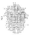
- the pump apparatus comprises, as main components, a housing 20, a pump shaft 21 rotatably supported by the housing 20, a pump unit 22 provided within the housing 20 and driven through the pump shaft 21, and a pulley (rotary drive member) 23 coaxially fixed to one end of the pump shaft 21.
- the housing 20 consists of a front housing 20a and a rear housing 20b fixed to the rear side of the front housing 20a by use of bolts.
- a substantially cylindrical tip end portion 20c is formed at one end of the front housing 20a.
- the outer races 24a of two ball bearings 24 are fitted into and supported by the inner circumferential surface of the tip end portion 20c in such a manner that the outer races 24a are located adjacent to each other.
- the pump shaft 21 is fitted into and supported by the inner races 24b of the ball bearings 24. Axial movement of the inner races 24b is restricted by two snap rings 21a.
- a stepped cylindrical inner space 20d is formed within the front housing 20a to be coaxial with the pump shaft 21.
- An annular fluid-passage space 20e is eccentrically formed at an intermediate portion of the inner space 20d in the axial direction of the pump shaft 21.
- a front side plate 25 and a rear side plate 26 each assuming a disk-like shape are sildably fitted into front and rear portions, respectively, of the inner space 20d.
- the pump unit 22, which will be described later, is disposed between the front side plate 25 and the rear side plate 26.
- the rear housing 20b has a cylindrical portion 20f formed on the front face thereof.
- the cylindrical portion 20f is fitted into the inner space 20d of the front housing 20a to face the rear face of the rear side plate 26 with a slight clearance formed therebetween.
- a depression 20g formed on the front face of the cylindrical portion 20f defines a pressure chamber 27 in cooperation with the rear face of the rear side plate 26.
- An O-ring 28a is interposed between the front housing 20a and the rear housing 20b in order to implement a fluid-tight seal therebetween.
- An O-ring 28b is interposed between the rear side plate 26 and the cylindrical portion 20f of the rear housing 20b in order to implement a fluid-tight seal around the pressure chamber 27.
- the pressure chamber 27 communicates with an outlet port 30 having a metering orifice 29.
- the pump unit 22 located between the front side plate 25 and the rear side plate 26 is a vane pump which consists of a cam ring 22a, a rotor 22b, and a plurality of vanes 22d.
- the cam ring 22a is fixed to the front housing 20a.
- a cam surface having a generally elliptical cross section is formed on the inner wall of the cam ring 22a.
- the rotor 22b is coupled with the inner end of the pump shaft 21 to be rotated thereby.
- the vanes 22d are slidably accommodated in radial slits 22c formed in the rotor 22b, and the radially outer ends of the vanes 22d are always in contact with the cam surface of the cam ring 22a.
- the O-ring 28b elastically presses the rear side plate 26 toward the rear face of the cam ring 22a of the pump unit 22, so that the cam ring 22a is sandwiched between the front and rear side plates 25 and 26 and held in place by pressure produced from elastic force.
- the cam ring 22a is located within the width of the passage space 20e with respect to the front/back direction.
- the cam ring 22a and the side plates 25 and 26 are supported by two positioning pins 31 (see FIG. 4), which extend parallel to the axis of the pump shaft 22, whereby the cam ring 22a and the side plates 25 and 26 are positioned in the circumferential direction relative to the front housing 20a.
- a pair of suction ports 32 for introducing operation fluid from the passage space 20e to the interior of the pump unit 22 are formed on each of the side plates 25 and 26 to be located at symmetric positions with resect to the rotary axis of the rotor 22b.
- a pair of discharge ports 33 for discharging operation fluid from the pump unit 22 to the pressure chamber 27 are formed on the rear side plate 26 in such a manner that the discharge ports 33 are located at symmetric positions with resect to the rotary axis of the rotor 22b and are angularly offset by about 90 degrees from the suction ports 32 (see FIG. 4).
- FIG. 3 shows a cross section taken along line III-III in FIG. 4 in order to show both the suction ports 32 and the discharge ports 33.
- a valve bore 35 of a flow control valve 34 is formed in the rear housing 20b coaxially with the rotary axis of the rotor 22b.
- the front end of the valve bore 35 communicates with the pressure chamber 27, and the rear end of the valve bore 35 is closed.
- a bypass passage 36 is formed in the housing 20 along a plane which includes the rotary axis of the rotor 22b and perpendicularly intersects a line connecting the suction ports 32, to thereby establish communication between an axially intermediate portion of the wall surface of the valve bore 35 and the passage space 20e.
- the bypass passage 36 is formed by first and second passages 36a and 36b formed in the rear housing 20b to intersect each other perpendicularly, a corner guide 36d fitted into the first passage 36a in a fluid-tight manner and smoothly connecting the passages 36a and 36b, and a third passage 36c formed in the front housing 20a.
- a suction passage 37 for receiving operation fluid from a reservoir is connected to the first passage 36a at a position 36e on the pressure chamber 27 side and in proximity to the valve bore 35.
- a spool valve body 38 for opening and closing the bypass passage 36 is slidably fitted into the valve bore 35 of the flow control valve 34, and is elastically urged toward the pressure chamber 27 by means of a spring 39 disposed between the spool valve 38 and the bottom surface of the valve bore 35.
- the spool valve body 38 is stopped at the advanced position at which a protrusion 38a coaxially extending from the tip end of the spool valve body 38 abuts the rear side plate 26.
- the flow control valve 34 is closed.
- the tip end of the spool valve body 38 is located rearward from the bottom surface of the depression 20g defining the pressure chamber 27, so that a relatively large space is formed at the center portion of the pressure chamber 27.
- a communication passage 41 having a throttle portion is formed in the rear housing 20b in order to connect a discharge passage 40 located on the downstream side of the metering orifice 29 and the space in the valve bore 35 located on the rear side of the spool valve body 38.
- the pulley 23 has a boss portion 23a and a rim portion 23b, which are formed integrally to be coaxial with each other.
- the boss portion 23a is fixed to one end of the pump shaft 21 projecting from the front end portion 20c of the front housing 20a.
- the rim portion 23b is axially offset relative to the boss portion 23a in order to cover a most portion of the front end portion 20c of the front housing 20a, which supports the ball bearings 24.
- a groove portion 23c (drive force input portion) consisting of a plurality of V grooves is formed on the outer circumference of the rim portion 23b.
- An unillustrated drive belt is extended between and wound around the groove portion 23c of the pulley 23 and an unillustrated pulley attached to an output shaft of an engine of a vehicle.
- a plane L passing though the widthwise center of the groove portion 23c (hereinafter referred to as the "widthwise center plane L") is located at the midpoint between the centers of balls of one bearing 24 and the centers of balls of the other bearing 24.
- the spool valve body 38 retracts accordingly in order to increase the opening of the flow control valve 34 to thereby increase the return flow.
- the flow rate of the operation fluid discharged from the outlet port 30 is maintained substantially constant.
- the groove portion 23c around which a drive belt is wound is disposed such that the widthwise center plane L of the groove portion 23c is located at the midpoint between the centers of balls of one bearing 24 and the centers of balls of the other bearing 24.
- the tensile force W which the drive belt applies to the pulley 23 in a direction perpendicular to the axial direction is born equally by the two ball bearings 24, so that the force acting on each ball bearing 24 becomes half the tensile force W. Therefore, ball bearings having a small load capacity can be used as the ball bearings 24. Further, since no moment which inclines the pump shaft 21 supported by the ball bearings 24 is produced, the distance between the two bearings 24 can be reduced.
- the overall size of the pump apparatus can be reduced through a reduction in size of the tip end portion 20c of the front housing 20a, which supports the ball bearings 24. Moreover, since the ball bearings 24 are disposed within the tip end portion 20c of the front housing 20a to be located adjacent to each other, misalignment between the respective centers of the ball bearings 24 does not occur. Therefore, rotation of the pump shaft 21 does not become unsmooth.
- the widthwise center plane L of the groove portion 23c around which a drive belt is wound is located at the midpoint between the centers of balls of one bearing 24 and the centers of balls of the other bearing 24, the force acting on each ball bearing 24 becomes half the tensile force W.
- the present invention is not limited thereto; the widthwise center plane L of the groove portion 23c may be located at any other point between the centers of balls of one bearing 24 and the centers of balls of the other bearing 24.
- the force or load does not act equally on the two ball bearings 24, and one of the ball bearings 24 receives a larger force or load than does the other ball bearing 24.
- the larger force or load is smaller than the tensile force W.
- the groove portion 23c is disposed such that its widthwise center plane L is located between the respective centers of the bearings.
- the number of bearings for supporting the pump shaft 21 is not limited to two. In the case in which a rolling bearing such as a double-row bearing or a slide bearing having a sufficient length is employed, a single bearing may be disposed, in which case the groove portion 23c is disposed such that its widthwise center plane L is located at the center of the bearing.
- FIG. 5 shows a second embodiment of the present invention.
- the pulley 23 serves as a rotary drive member attached to one end of the pump shaft 21.
- the second embodiment differs from the first embodiment in that a gear 42 is used in place of the pulley 23.
- the gear 42 has substantially the same shape as that of the pulley 23, in place of the groove portion 23c, a tooth portion (drive force input portion) 42a is formed on the outer circumference.
- the widthwise center plane La of the tooth portion 42a is located at the midpoint between the centers of balls of one bearing 24 and the centers of balls of the other bearing 24.
- the tooth portion 42a at the outer circumference of the gear 42 is in meshing engagement with a drive gear (not shown), which is driven by the engine of the vehicle.
- the tooth portion 42a of the gear 42 in meshing engagement with the drive gear is disposed such that its widthwise center plane La is located at the midpoint between the centers of balls of one bearing 24 and the centers of balls of the other bearing 24.
- a balanced-type vane pump capable of canceling out radial forces acting on the pump shaft 21 is used as the pump unit 22.
- Such a balanced-type vane pump is suitable for the pump apparatus of the present invention which is designed in such a manner that the pump shaft 21 does not incline due to force (tensile force or thrust force) acting on the rotary drive member (the pulley 23 or the gear 42).
- the present invention is not limited thereto, and may be applied to a trochoid pump or a gear pump. Even in such a case, the above-described action and effects can be achieved.
- a moment which inclines the pump shaft is not generated, and thus a cantilever-type compact support structure can be employed to support the pump shaft.
- the distance between the two bearings can be reduced.
- the tensile force or thrust force which the rotation drive member receives from a drive belt or drive gear is born by the two bearings, and the force or load acting on each bearing becomes smaller than that received by the rotation drive member.
- ball bearings having a small load capacity can be used to support the pump shaft.
- the distance between the two bearings can be reduced.
- the overall size of the pump apparatus can be reduced through a reduction in size of the tip end portion of the housing supporting the bearings.
- the two bearings are disposed within the tip end portion of the housing to be located in close proximity to each other, so that misalignment between the respective centers of the ball bearings does not occur. Therefore, rotation of the pump shaft does not become unsmooth.
- the pump unit In the case in which the pump unit is a balanced-type vane pump, the pump unit does not apply radial force to the pump shaft, which radial force would otherwise hinder reduction in size of the pump apparatus.
- a pump shaft is rotatably supported by two bearings and is connected to a pump unit.
- a rotary drive member is fixed to one end of the pump shaft projecting from the tip end portion of the housing.
- the rotary drive member includes a boss portion fixed to the one end of the pump shaft projecting from the housing, and a rim portion integral with the boss portion.
- the rim portion is offset from the boss portion to cover at least a portion of the tip end portion of the housing.
- a groove portion for receiving a drive belt is formed on the outer circumference of the rim portion.
- the widthwise center plane of the groove portion is located between the respective centers of the two bearings.
- a tooth portion engageable with a drive gear may be formed on the outer circumference of the rim portion.
- the pump unit is of a balanced vane type.
Landscapes
- Engineering & Computer Science (AREA)
- Mechanical Engineering (AREA)
- General Engineering & Computer Science (AREA)
- Details And Applications Of Rotary Liquid Pumps (AREA)
- Rotary Pumps (AREA)
- Reciprocating Pumps (AREA)
Abstract
Description
- The disclosure of Japanese Patent Application No. 2000-225496 filed on July 26, 2000 is incorporated herein by reference in this entirety.
- The present invention relates to a pump apparatus of relatively small size, and more particularly to an improvement on the structure of a pump shaft drive portion of a pump apparatus.
- FIG. 1 shows a conventional compact pump apparatus for supplying operation fluid to a power steering apparatus of a vehicle. In the pump apparatus, a
pump shaft 2 for driving apump unit 5 disposed within ahousing 1 is supported by a ball bearing 3 and a slide bearing 4; and a pulley 9 is fixed to one end of thepump shaft 2 projecting from thehousing 1. Agroove portion 9a is formed on the outer circumference of the pulley 9, around which a drive belt (not shown) is wound in order to transmit rotation of an engine of the vehicle to thepump shaft 2. As a result, thepump unit 5 is operated, so that operation fluid sucked from aninlet port 6 into the interior of thepump unit 5 is discharged from anoutlet port 8 via apressure chamber 7. Generally, thepump unit 5 is a balanced-type vane pump. In such a balanced-type vane pump, a plurality of (typically, two) suction ports are provided at symmetric positions; and a plurality of (typically, two) discharge ports are provided at symmetric positions. Therefore, radial forces generated within thepump unit 5 are cancelled out, so that almost no net load acts on thepump shaft 2. Accordingly, when merely the pump unit is considered, only one end of thepump shaft 2 is required to be supported by use of a bearing having a small load capacity. - However, since a large tension is applied to the drive belt in order to prevent slippage, the following problem occurs. That is, a large tensile force W1 acts on the
pump shaft 2 perpendicularly at a position corresponding to a center plane L1 of the drive belt wound around thegroove portion 9a of the pulley 9. Since the center plane L1 is located on the tip end side with respect to the ball bearing 3, a moment which inclines thepump shaft 2 is produced, and a force greater than the tensile force W1 acts on the ball bearing 3. Therefore, the ball bearing 3 must have a large load capacity; and the distance between the twobearings 3 and 4 must be increased. Therefore, the size of the bearing support portion of thehousing 1 increases. This problem of the bearing support portion of thehousing 1 having a large size is always present even in the case where both thebearings 3 and 4 are formed of ball bearings or slide bearings, or in the case where thebearings 3 and 4 are replaced with a single long slide bearing. - FIG. 2 shows another conventional pump apparatus of a compact type. In the pump apparatus, opposite ends of a
pump shaft 11 for driving apump unit 14 are supported byslide bearings housing 10 to be located on the front and rear sides, respectively, of thepump unit 14; and agear 17 is fixed to one end of thepump shaft 11 projecting from thehousing 10. Rotation of an engine of the vehicle is transmitted to thegear 17 via a drive gear in meshing-engagement with atooth portion 17a of thegear 17. Thus, thepump shaft 11 is rotated to drive thepump unit 14, whereby operation fluid sucked from aninlet port 15 into the interior of thepump unit 14 is discharged from an outlet port (not shown) via apressure chamber 16. - In the conventional pump apparatus shown in FIG. 2, since the two
slide bearings pump shaft 11 are attached to two members which are fixed to each other by use of bolts, aligning the center axes of theslide bearings pump shaft 11 cannot be expected. Therefore, the conventional pump apparatus shown in FIG. 2 has drawbacks of increased frictional torque and generation of vibration and noise. - In view of the foregoing, an object of the present invention is to provide a pump apparatus which can solve the various problems involved in conventional pump apparatuses.
- To achieve the above-object, the present invention provides a pump apparatus which is driven by drive force from a drive source, comprising a housing; a bearing member provided within a tip end portion of the housing; a pump shaft rotatably supported by the bearing member, one end of the pump shaft projecting from the tip end portion of the housing; a pump unit accommodated within the housing and operated through rotation of the pump shaft; and a drive member fixed to the one end of the pump shaft projecting from the housing and adapted to transfer drive force from the drive source to the pump shaft. The drive member includes a drive force input portion to which the drive force is transferred from the drive source. The center of the bearing member in the axial direction of the pump shaft coincides with the center of the drive force input portion in the axial direction of the pump shaft.
- Preferably, the drive member includes a boss portion fixed to the one end of the pump shaft projecting from the housing, and a rim portion integral with the boss portion, the rim portion being offset from the boss portion to cover at least a portion of the tip end portion of the housing; and the drive input portion is formed on the outer circumference of the rim portion.
- Preferably, the bearing member consists of two bearings disposed adjacent to each other; and the center of the drive force input portion in the axial direction of the pump shaft is located between the respective centers of the two bearings in the axial direction of the pump shaft.
- The drive force input portion may be a groove portion which is engaged with a drive belt extended between and wound around the groove portion and a pulley of the drive source. In this case, the center of the groove portion in the axial direction of the pump shaft is located between the respective centers of the two bearings in the axial direction of the pump shaft.
- The drive force input portion may be a tooth portion which is in meshing-engaged with a drive gear of the drive source. In this case, the center of the tooth portion in the axial direction of the pump shaft is located between the respective centers of the two bearings in the axial direction of the pump shaft.
- Preferably, the pump unit is a vane pump. More preferably, the vane pump is a balanced-type vane pump having a plurality of suction ports disposed symmetrically with respect to the pump shaft and a plurality of discharge ports disposed symmetrically with respect to the pump shaft.
- Various other objects, features and many of the attendant advantages of the present invention will be readily appreciated as the same becomes better understood by reference to the following detailed description of the preferred embodiments when considered in connection with the accompanying drawings, in which:
- FIG. 1 is a cross-sectional view of a conventional pump apparatus;
- FIG. 2 is a cross-sectional view of another conventional pump apparatus;
- FIG. 3 is a vertical cross-sectional view of a pump apparatus according to a first embodiment of the present invention;
- FIG. 4 is a cross-sectional view taken along line IV-IV in FIG. 3; and
- FIG. 5 is a cross-sectional view of a bearing support portion of a pump apparatus according to a second embodiment of the present invention.
-
- First, a pump apparatus according to a first embodiment of the present invention will be described with reference to FIGS. 3 and 4. The pump apparatus comprises, as main components, a
housing 20, apump shaft 21 rotatably supported by thehousing 20, apump unit 22 provided within thehousing 20 and driven through thepump shaft 21, and a pulley (rotary drive member) 23 coaxially fixed to one end of thepump shaft 21. - The
housing 20 consists of afront housing 20a and arear housing 20b fixed to the rear side of thefront housing 20a by use of bolts. A substantially cylindricaltip end portion 20c is formed at one end of thefront housing 20a. Theouter races 24a of twoball bearings 24 are fitted into and supported by the inner circumferential surface of thetip end portion 20c in such a manner that theouter races 24a are located adjacent to each other. Thepump shaft 21 is fitted into and supported by theinner races 24b of theball bearings 24. Axial movement of theinner races 24b is restricted by twosnap rings 21a. A stepped cylindricalinner space 20d is formed within thefront housing 20a to be coaxial with thepump shaft 21. An annular fluid-passage space 20e is eccentrically formed at an intermediate portion of theinner space 20d in the axial direction of thepump shaft 21. Afront side plate 25 and arear side plate 26 each assuming a disk-like shape are sildably fitted into front and rear portions, respectively, of theinner space 20d. Thepump unit 22, which will be described later, is disposed between thefront side plate 25 and therear side plate 26. - The
rear housing 20b has acylindrical portion 20f formed on the front face thereof. Thecylindrical portion 20f is fitted into theinner space 20d of thefront housing 20a to face the rear face of therear side plate 26 with a slight clearance formed therebetween. Adepression 20g formed on the front face of thecylindrical portion 20f defines apressure chamber 27 in cooperation with the rear face of therear side plate 26. An O-ring 28a is interposed between thefront housing 20a and therear housing 20b in order to implement a fluid-tight seal therebetween. An O-ring 28b is interposed between therear side plate 26 and thecylindrical portion 20f of therear housing 20b in order to implement a fluid-tight seal around thepressure chamber 27. Thepressure chamber 27 communicates with anoutlet port 30 having ametering orifice 29. - The
pump unit 22 located between thefront side plate 25 and therear side plate 26 is a vane pump which consists of a cam ring 22a, a rotor 22b, and a plurality of vanes 22d. The cam ring 22a is fixed to thefront housing 20a. A cam surface having a generally elliptical cross section is formed on the inner wall of the cam ring 22a. The rotor 22b is coupled with the inner end of thepump shaft 21 to be rotated thereby. The vanes 22d are slidably accommodated in radial slits 22c formed in the rotor 22b, and the radially outer ends of the vanes 22d are always in contact with the cam surface of the cam ring 22a. The O-ring 28b elastically presses therear side plate 26 toward the rear face of the cam ring 22a of thepump unit 22, so that the cam ring 22a is sandwiched between the front andrear side plates passage space 20e with respect to the front/back direction. The cam ring 22a and theside plates pump shaft 22, whereby the cam ring 22a and theside plates front housing 20a. - A pair of
suction ports 32 for introducing operation fluid from thepassage space 20e to the interior of thepump unit 22 are formed on each of theside plates discharge ports 33 for discharging operation fluid from thepump unit 22 to thepressure chamber 27 are formed on therear side plate 26 in such a manner that thedischarge ports 33 are located at symmetric positions with resect to the rotary axis of the rotor 22b and are angularly offset by about 90 degrees from the suction ports 32 (see FIG. 4). Notably, FIG. 3 shows a cross section taken along line III-III in FIG. 4 in order to show both thesuction ports 32 and thedischarge ports 33. - A valve bore 35 of a
flow control valve 34 is formed in therear housing 20b coaxially with the rotary axis of the rotor 22b. The front end of the valve bore 35 communicates with thepressure chamber 27, and the rear end of the valve bore 35 is closed. Abypass passage 36 is formed in thehousing 20 along a plane which includes the rotary axis of the rotor 22b and perpendicularly intersects a line connecting thesuction ports 32, to thereby establish communication between an axially intermediate portion of the wall surface of the valve bore 35 and thepassage space 20e. Thebypass passage 36 is formed by first andsecond passages rear housing 20b to intersect each other perpendicularly, acorner guide 36d fitted into thefirst passage 36a in a fluid-tight manner and smoothly connecting thepassages third passage 36c formed in thefront housing 20a. Asuction passage 37 for receiving operation fluid from a reservoir (not shown) is connected to thefirst passage 36a at aposition 36e on thepressure chamber 27 side and in proximity to the valve bore 35. - A
spool valve body 38 for opening and closing thebypass passage 36 is slidably fitted into the valve bore 35 of theflow control valve 34, and is elastically urged toward thepressure chamber 27 by means of aspring 39 disposed between thespool valve 38 and the bottom surface of the valve bore 35. When theflow control valve 34 does not operate, thespool valve body 38 is stopped at the advanced position at which aprotrusion 38a coaxially extending from the tip end of thespool valve body 38 abuts therear side plate 26. Thus, theflow control valve 34 is closed. In this state, the tip end of thespool valve body 38 is located rearward from the bottom surface of thedepression 20g defining thepressure chamber 27, so that a relatively large space is formed at the center portion of thepressure chamber 27. Acommunication passage 41 having a throttle portion is formed in therear housing 20b in order to connect adischarge passage 40 located on the downstream side of themetering orifice 29 and the space in the valve bore 35 located on the rear side of thespool valve body 38. - The
pulley 23 has aboss portion 23a and arim portion 23b, which are formed integrally to be coaxial with each other. Theboss portion 23a is fixed to one end of thepump shaft 21 projecting from thefront end portion 20c of thefront housing 20a. Therim portion 23b is axially offset relative to theboss portion 23a in order to cover a most portion of thefront end portion 20c of thefront housing 20a, which supports theball bearings 24. Agroove portion 23c (drive force input portion) consisting of a plurality of V grooves is formed on the outer circumference of therim portion 23b. An unillustrated drive belt is extended between and wound around thegroove portion 23c of thepulley 23 and an unillustrated pulley attached to an output shaft of an engine of a vehicle. In the present embodiment, a plane L passing though the widthwise center of thegroove portion 23c (hereinafter referred to as the "widthwise center plane L") is located at the midpoint between the centers of balls of onebearing 24 and the centers of balls of theother bearing 24. - When rotation of the output shaft of the engine is transmitted to the
pump shaft 21 via the drive belt and thepulley 23, the rotor 22b of thepump unit 22 rotates. As a result, operation oil introduced from the unillustrated reservoir to thesuction passage 37 flows into the spaces between the vanes 22d of thepump unit 22 via thebypass passage 36, thepassage space 20e, and thesuction ports 32. When the rotational speed of thepump shaft 21 is low, theflow control valve 34 maintains the closed state, so that the entirety of the operation fluid is supplied from theoutlet port 30 to, for example, a power steering apparatus via themetering orifice 29 and thedischarge passage 40. When the flow rate of the operation fluid discharged from theoutlet port 30 via themetering orifice 29 increases with the rotational speed of thepump shaft 21, the pressure difference across themetering orifice 29 increases accordingly. When the flow rate reaches a predetermined level, the pressure difference between the front and rear sides of thespool valve body 38 reaches a predetermined level, and thespool valve body 38 retracts against thespring 39. As a result, theflow control valve 34 opens, and the operation oil within thepressure chamber 27 returns to thesuction ports 32 of thepump unit 22 via thebypass passage 36 and thepassage space 20e. Specifically, when the rotational speed of thepump shaft 21 increases and the flow rate of the operation fluid discharged from theoutlet port 30 is about to increase, thespool valve body 38 retracts accordingly in order to increase the opening of theflow control valve 34 to thereby increase the return flow. Through this automatic regulation, the flow rate of the operation fluid discharged from theoutlet port 30 is maintained substantially constant. - In the above-described first embodiment, the
groove portion 23c around which a drive belt is wound is disposed such that the widthwise center plane L of thegroove portion 23c is located at the midpoint between the centers of balls of onebearing 24 and the centers of balls of theother bearing 24. The tensile force W which the drive belt applies to thepulley 23 in a direction perpendicular to the axial direction is born equally by the twoball bearings 24, so that the force acting on eachball bearing 24 becomes half the tensile force W. Therefore, ball bearings having a small load capacity can be used as theball bearings 24. Further, since no moment which inclines thepump shaft 21 supported by theball bearings 24 is produced, the distance between the twobearings 24 can be reduced. Therefore, the overall size of the pump apparatus can be reduced through a reduction in size of thetip end portion 20c of thefront housing 20a, which supports theball bearings 24. Moreover, since theball bearings 24 are disposed within thetip end portion 20c of thefront housing 20a to be located adjacent to each other, misalignment between the respective centers of theball bearings 24 does not occur. Therefore, rotation of thepump shaft 21 does not become unsmooth. - In the above-described embodiment, since the widthwise center plane L of the
groove portion 23c around which a drive belt is wound is located at the midpoint between the centers of balls of onebearing 24 and the centers of balls of theother bearing 24, the force acting on eachball bearing 24 becomes half the tensile force W. However, the present invention is not limited thereto; the widthwise center plane L of thegroove portion 23c may be located at any other point between the centers of balls of onebearing 24 and the centers of balls of theother bearing 24. In such a case, the force or load does not act equally on the twoball bearings 24, and one of theball bearings 24 receives a larger force or load than does theother ball bearing 24. However, the larger force or load is smaller than the tensile force W. Moreover, a moment which inclines thepump shaft 21 supported by theball bearings 24 is not produced. Accordingly, as compared with the conventional pump apparatuses shown in FIGS. 1 and 2, smaller ball bearings having a smaller load capacity can be used for theball bearings 24, and the distance between theball bearings 24 can be reduced. Therefore, the size of thetip end portion 20c of thefront housing 20a supporting theball bearings 24 can be reduced in order to reduce the overall size of the pump apparatus. In the above-described embodiment, although the twoball bearings 24 are used to support thepump shaft 21, thebearings 24 are not limited to the ball bearings. Slide bearings or needle roller bearings can be used for thebearings 24. In this case, thegroove portion 23c is disposed such that its widthwise center plane L is located between the respective centers of the bearings. The number of bearings for supporting thepump shaft 21 is not limited to two. In the case in which a rolling bearing such as a double-row bearing or a slide bearing having a sufficient length is employed, a single bearing may be disposed, in which case thegroove portion 23c is disposed such that its widthwise center plane L is located at the center of the bearing. - FIG. 5 shows a second embodiment of the present invention. In the above-described first embodiment, the
pulley 23 serves as a rotary drive member attached to one end of thepump shaft 21. The second embodiment differs from the first embodiment in that agear 42 is used in place of thepulley 23. Although thegear 42 has substantially the same shape as that of thepulley 23, in place of thegroove portion 23c, a tooth portion (drive force input portion) 42a is formed on the outer circumference. As in the first embodiment, the widthwise center plane La of thetooth portion 42a is located at the midpoint between the centers of balls of onebearing 24 and the centers of balls of theother bearing 24. In the second embodiment, thetooth portion 42a at the outer circumference of thegear 42 is in meshing engagement with a drive gear (not shown), which is driven by the engine of the vehicle. Thus, thepump shaft 21 is rotated by the engine. Thetooth portion 42a of thegear 42 in meshing engagement with the drive gear is disposed such that its widthwise center plane La is located at the midpoint between the centers of balls of onebearing 24 and the centers of balls of theother bearing 24. By virtue of this arrangement, thrust force Wa which the drive gear applies to thetooth portion 42a in a direction perpendicular to the axial direction is born equally by the twoball bearings 24. Since the structure of the remaining portion, the action and effect, and the range of application are the same as those of the first embodiment, their repeated descriptions are omitted. - In the above-described embodiment, a balanced-type vane pump capable of canceling out radial forces acting on the
pump shaft 21 is used as thepump unit 22. Such a balanced-type vane pump is suitable for the pump apparatus of the present invention which is designed in such a manner that thepump shaft 21 does not incline due to force (tensile force or thrust force) acting on the rotary drive member (thepulley 23 or the gear 42). However, the present invention is not limited thereto, and may be applied to a trochoid pump or a gear pump. Even in such a case, the above-described action and effects can be achieved. - In the pump apparatus according present invention, a moment which inclines the pump shaft is not generated, and thus a cantilever-type compact support structure can be employed to support the pump shaft. When two bearings are used to support the pump shaft, the distance between the two bearings can be reduced. Moreover, the tensile force or thrust force which the rotation drive member receives from a drive belt or drive gear is born by the two bearings, and the force or load acting on each bearing becomes smaller than that received by the rotation drive member. Accordingly, ball bearings having a small load capacity can be used to support the pump shaft. Further, when two bearings are used to support the pump shaft, the distance between the two bearings can be reduced. Therefore, the overall size of the pump apparatus can be reduced through a reduction in size of the tip end portion of the housing supporting the bearings. Moreover, when two bearings are used to support the pump shaft, the two bearings are disposed within the tip end portion of the housing to be located in close proximity to each other, so that misalignment between the respective centers of the ball bearings does not occur. Therefore, rotation of the pump shaft does not become unsmooth.
- In the case in which the pump unit is a balanced-type vane pump, the pump unit does not apply radial force to the pump shaft, which radial force would otherwise hinder reduction in size of the pump apparatus.
- Obviously, numerous modifications and variations of the present invention are possible in light of the above teachings. It is therefore to be understood that within the scope of the appended claims, the present invention may be practiced otherwise than as specifically described herein.
- In a pump housing of a pump apparatus, a pump shaft is rotatably supported by two bearings and is connected to a pump unit. A rotary drive member is fixed to one end of the pump shaft projecting from the tip end portion of the housing. The rotary drive member includes a boss portion fixed to the one end of the pump shaft projecting from the housing, and a rim portion integral with the boss portion. The rim portion is offset from the boss portion to cover at least a portion of the tip end portion of the housing. A groove portion for receiving a drive belt is formed on the outer circumference of the rim portion. The widthwise center plane of the groove portion is located between the respective centers of the two bearings. In place of the groove portion, a tooth portion engageable with a drive gear may be formed on the outer circumference of the rim portion. Preferably, the pump unit is of a balanced vane type.
Claims (7)
- A pump apparatus which is driven by drive force from a drive source, comprising:a housing;a bearing member provided within a tip end portion of said housing;a pump shaft rotatably supported by said bearing member, one end of said pump shaft projecting from the tip end portion of said housing;a pump unit accommodated within said housing and operated through rotation of said pump shaft; anda drive member fixed to the one end of said pump shaft projecting from said housing and adapted to transfer drive force from said drive source to said pump shaft, whereinsaid drive member includes a drive force input portion to which the drive force is transferred from said drive source, the center of said bearing member in the axial direction of said pump shaft coinciding with the center of said drive force input portion in the axial direction of said pump shaft.
- A pump apparatus according to claim 1, whereinsaid drive member includes a boss portion fixed to the one end of said pump shaft projecting from said housing, and a rim portion integral with said boss portion, said rim portion being offset from said boss portion to cover at least a portion of the tip end portion of said housing; andsaid drive input portion is formed on the outer circumference of said rim portion.
- A pump apparatus according to claim 2, whereinsaid bearing member consists of two bearings disposed adjacent to each other; andthe center of said drive force input portion in the axial direction of said pump shaft is located between the respective centers of said two bearings in the axial direction of said pump shaft.
- A pump apparatus according to claim 3, whereinsaid drive force input portion is a groove portion which is engaged with a drive belt extended between and wound around said groove portion and a pulley of said drive source; andthe center of said groove portion in the axial direction of said pump shaft is located between the respective centers of said two bearings in the axial direction of said pump shaft.
- A pump apparatus according to claim 3, whereinsaid drive force input portion is a tooth portion which is in meshing-engaged with a drive gear of said drive source; andthe center of said tooth portion in the axial direction of said pump shaft is located between the respective centers of said two bearings in the axial direction of said pump shaft.
- A pump apparatus according to claim 1, wherein said pump unit is a vane pump.
- A pump apparatus according to claim 6, wherein the vane pump is a balanced-type vane pump having a plurality of suction ports disposed symmetrically with respect to said pump shaft and a plurality of discharge ports disposed symmetrically with respect to said pump shaft.
Applications Claiming Priority (2)
| Application Number | Priority Date | Filing Date | Title |
|---|---|---|---|
| JP2000225496A JP3823015B2 (en) | 2000-07-26 | 2000-07-26 | Pump device |
| JP2000225496 | 2000-07-26 |
Publications (2)
| Publication Number | Publication Date |
|---|---|
| EP1176311A2 true EP1176311A2 (en) | 2002-01-30 |
| EP1176311A3 EP1176311A3 (en) | 2003-01-02 |
Family
ID=18719259
Family Applications (1)
| Application Number | Title | Priority Date | Filing Date |
|---|---|---|---|
| EP01113729A Withdrawn EP1176311A3 (en) | 2000-07-26 | 2001-06-05 | Pump apparatus |
Country Status (4)
| Country | Link |
|---|---|
| US (1) | US6497565B2 (en) |
| EP (1) | EP1176311A3 (en) |
| JP (1) | JP3823015B2 (en) |
| TW (1) | TW500879B (en) |
Cited By (3)
| Publication number | Priority date | Publication date | Assignee | Title |
|---|---|---|---|---|
| WO2010096256A3 (en) * | 2009-02-20 | 2011-04-07 | Standex International Corporation | Sliding vane pump with internal cam ring |
| US8419384B2 (en) | 2007-10-18 | 2013-04-16 | Standex International Corporation | Sliding vane pump |
| CN110259699A (en) * | 2019-07-24 | 2019-09-20 | 重庆水泵厂有限责任公司 | Multi-stage pump or turbine combined structure |
Families Citing this family (8)
| Publication number | Priority date | Publication date | Assignee | Title |
|---|---|---|---|---|
| US7167525B2 (en) * | 2002-06-21 | 2007-01-23 | Pulse-Link, Inc. | Ultra-wideband communication through twisted-pair wire media |
| US6666670B1 (en) | 2003-05-22 | 2003-12-23 | Visteon Global Technologies, Inc. | Power steering pump |
| US9454657B2 (en) * | 2004-12-03 | 2016-09-27 | Bce Inc. | Security access device and method |
| DE102006008757A1 (en) * | 2006-02-24 | 2007-08-30 | Daimlerchrysler Ag | Water pump, for a vehicle motor, is within the hollow zone of the function wheel journal coupled to a drive by a shaft through the journal wall |
| WO2007142995A2 (en) * | 2006-05-31 | 2007-12-13 | Metaldyne Company, Llc | Compact pump arrangement |
| US20080219326A1 (en) * | 2007-03-09 | 2008-09-11 | John Santhoff | Wireless multimedia link |
| WO2013176143A1 (en) * | 2012-05-21 | 2013-11-28 | ナブテスコオートモーティブ株式会社 | Vacuum pump |
| CN105114300A (en) * | 2015-09-25 | 2015-12-02 | 泊头市广腾机械设备制造有限公司 | Cantilever easy-demounting sliding vane pump |
Family Cites Families (8)
| Publication number | Priority date | Publication date | Assignee | Title |
|---|---|---|---|---|
| GB716342A (en) * | 1952-02-15 | 1954-10-06 | Megator Pumps Compressor | Improvements in rotary pumps or compressors |
| GB754427A (en) * | 1953-12-17 | 1956-08-08 | Heinz Teves | Rotary vane pump with disc-shaped rotor |
| US3340816A (en) * | 1965-10-11 | 1967-09-12 | Weatherhead Co | Vane pump or motor |
| JPS6328892U (en) * | 1986-08-12 | 1988-02-25 | ||
| JPH0756274B2 (en) * | 1987-03-20 | 1995-06-14 | サンデン株式会社 | Scroll compressor |
| JP2602773Y2 (en) * | 1993-10-08 | 2000-01-24 | 株式会社小松製作所 | Water pump for internal combustion engine |
| US5664941A (en) * | 1995-12-22 | 1997-09-09 | Zexel Usa Corporation | Bearings for a rotary vane compressor |
| KR0130912Y1 (en) * | 1995-12-27 | 1999-01-15 | 조봉현 | Vane Pump |
-
2000
- 2000-07-26 JP JP2000225496A patent/JP3823015B2/en not_active Expired - Fee Related
-
2001
- 2001-05-23 TW TW090112390A patent/TW500879B/en not_active IP Right Cessation
- 2001-06-01 US US09/870,794 patent/US6497565B2/en not_active Expired - Fee Related
- 2001-06-05 EP EP01113729A patent/EP1176311A3/en not_active Withdrawn
Non-Patent Citations (1)
| Title |
|---|
| None |
Cited By (4)
| Publication number | Priority date | Publication date | Assignee | Title |
|---|---|---|---|---|
| US8419384B2 (en) | 2007-10-18 | 2013-04-16 | Standex International Corporation | Sliding vane pump |
| US9188005B2 (en) | 2007-10-18 | 2015-11-17 | Standex International Corporation | Sliding vane pump with internal cam ring |
| WO2010096256A3 (en) * | 2009-02-20 | 2011-04-07 | Standex International Corporation | Sliding vane pump with internal cam ring |
| CN110259699A (en) * | 2019-07-24 | 2019-09-20 | 重庆水泵厂有限责任公司 | Multi-stage pump or turbine combined structure |
Also Published As
| Publication number | Publication date |
|---|---|
| JP3823015B2 (en) | 2006-09-20 |
| US20020012597A1 (en) | 2002-01-31 |
| EP1176311A3 (en) | 2003-01-02 |
| JP2002039054A (en) | 2002-02-06 |
| TW500879B (en) | 2002-09-01 |
| US6497565B2 (en) | 2002-12-24 |
Similar Documents
| Publication | Publication Date | Title |
|---|---|---|
| US6648611B2 (en) | Gerotor pump having an eccentric ring housing with an integral pressure chamber | |
| US8961157B2 (en) | Vane pump | |
| US6497565B2 (en) | Pump apparatus having drive force input portion aligned with pump shaft bearing member | |
| US6017202A (en) | Bi-directional gerotor-type fluid pump | |
| MXPA03005938A (en) | Lubrication pump for inter-axle differential. | |
| WO2018123682A1 (en) | Oil pump and balancer unit of oil pump integrated type | |
| JP3441100B2 (en) | Variable displacement pump | |
| US8651843B2 (en) | High efficiency fixed displacement vane pump | |
| US11268508B2 (en) | Variable displacement pump | |
| KR850000877B1 (en) | Oil pump | |
| KR100909311B1 (en) | Clutch assembly with gear pump | |
| WO2017013932A1 (en) | Pump device | |
| US8690557B2 (en) | Variable displacement vane pump | |
| US4347047A (en) | Hydraulic pump for power steering | |
| US6634876B2 (en) | Vane pump having a vane guide | |
| KR100325823B1 (en) | Oil Pump | |
| JP3643937B2 (en) | Vane pump | |
| JPH07167066A (en) | Double cartridge type oil pump | |
| JPH08291793A (en) | Vane pump | |
| JP3775193B2 (en) | Pump device | |
| JPS60203579A (en) | Vehicle power steering device | |
| JP3881827B2 (en) | Pump device | |
| US11982270B2 (en) | Pump device | |
| JP3593729B2 (en) | Vane pump | |
| JP2000054969A (en) | Variable displacement pump |
Legal Events
| Date | Code | Title | Description |
|---|---|---|---|
| PUAI | Public reference made under article 153(3) epc to a published international application that has entered the european phase |
Free format text: ORIGINAL CODE: 0009012 |
|
| AK | Designated contracting states |
Kind code of ref document: A2 Designated state(s): AT BE CH CY DE DK ES FI FR GB GR IE IT LI LU MC NL PT SE TR |
|
| AX | Request for extension of the european patent |
Free format text: AL;LT;LV;MK;RO;SI |
|
| PUAL | Search report despatched |
Free format text: ORIGINAL CODE: 0009013 |
|
| AK | Designated contracting states |
Kind code of ref document: A3 Designated state(s): AT BE CH CY DE DK ES FI FR GB GR IE IT LI LU MC NL PT SE TR |
|
| AX | Request for extension of the european patent |
Free format text: AL;LT;LV;MK;RO;SI |
|
| 17P | Request for examination filed |
Effective date: 20030409 |
|
| 17Q | First examination report despatched |
Effective date: 20030618 |
|
| AKX | Designation fees paid |
Designated state(s): DE FR GB |
|
| GRAP | Despatch of communication of intention to grant a patent |
Free format text: ORIGINAL CODE: EPIDOSNIGR1 |
|
| STAA | Information on the status of an ep patent application or granted ep patent |
Free format text: STATUS: THE APPLICATION IS DEEMED TO BE WITHDRAWN |
|
| 18D | Application deemed to be withdrawn |
Effective date: 20060126 |