EP1176310A2 - PEEK compressor coating - Google Patents
PEEK compressor coating Download PDFInfo
- Publication number
- EP1176310A2 EP1176310A2 EP01117678A EP01117678A EP1176310A2 EP 1176310 A2 EP1176310 A2 EP 1176310A2 EP 01117678 A EP01117678 A EP 01117678A EP 01117678 A EP01117678 A EP 01117678A EP 1176310 A2 EP1176310 A2 EP 1176310A2
- Authority
- EP
- European Patent Office
- Prior art keywords
- swash plate
- shoes
- piston
- compressor
- sliding
- Prior art date
- Legal status (The legal status is an assumption and is not a legal conclusion. Google has not performed a legal analysis and makes no representation as to the accuracy of the status listed.)
- Withdrawn
Links
Images

Classifications
-
- F—MECHANICAL ENGINEERING; LIGHTING; HEATING; WEAPONS; BLASTING
- F04—POSITIVE - DISPLACEMENT MACHINES FOR LIQUIDS; PUMPS FOR LIQUIDS OR ELASTIC FLUIDS
- F04B—POSITIVE-DISPLACEMENT MACHINES FOR LIQUIDS; PUMPS
- F04B27/00—Multi-cylinder pumps specially adapted for elastic fluids and characterised by number or arrangement of cylinders
- F04B27/08—Multi-cylinder pumps specially adapted for elastic fluids and characterised by number or arrangement of cylinders having cylinders coaxial with, or parallel or inclined to, main shaft axis
- F04B27/0873—Component parts, e.g. sealings; Manufacturing or assembly thereof
- F04B27/0878—Pistons
- F04B27/0886—Piston shoes
-
- F—MECHANICAL ENGINEERING; LIGHTING; HEATING; WEAPONS; BLASTING
- F04—POSITIVE - DISPLACEMENT MACHINES FOR LIQUIDS; PUMPS FOR LIQUIDS OR ELASTIC FLUIDS
- F04B—POSITIVE-DISPLACEMENT MACHINES FOR LIQUIDS; PUMPS
- F04B27/00—Multi-cylinder pumps specially adapted for elastic fluids and characterised by number or arrangement of cylinders
- F04B27/08—Multi-cylinder pumps specially adapted for elastic fluids and characterised by number or arrangement of cylinders having cylinders coaxial with, or parallel or inclined to, main shaft axis
- F04B27/10—Multi-cylinder pumps specially adapted for elastic fluids and characterised by number or arrangement of cylinders having cylinders coaxial with, or parallel or inclined to, main shaft axis having stationary cylinders
- F04B27/1036—Component parts, details, e.g. sealings, lubrication
- F04B27/1054—Actuating elements
-
- F—MECHANICAL ENGINEERING; LIGHTING; HEATING; WEAPONS; BLASTING
- F04—POSITIVE - DISPLACEMENT MACHINES FOR LIQUIDS; PUMPS FOR LIQUIDS OR ELASTIC FLUIDS
- F04B—POSITIVE-DISPLACEMENT MACHINES FOR LIQUIDS; PUMPS
- F04B39/00—Component parts, details, or accessories, of pumps or pumping systems specially adapted for elastic fluids, not otherwise provided for in, or of interest apart from, groups F04B25/00 - F04B37/00
-
- F—MECHANICAL ENGINEERING; LIGHTING; HEATING; WEAPONS; BLASTING
- F05—INDEXING SCHEMES RELATING TO ENGINES OR PUMPS IN VARIOUS SUBCLASSES OF CLASSES F01-F04
- F05C—INDEXING SCHEME RELATING TO MATERIALS, MATERIAL PROPERTIES OR MATERIAL CHARACTERISTICS FOR MACHINES, ENGINES OR PUMPS OTHER THAN NON-POSITIVE-DISPLACEMENT MACHINES OR ENGINES
- F05C2225/00—Synthetic polymers, e.g. plastics; Rubber
- F05C2225/12—Polyetheretherketones, e.g. PEEK
Definitions
- the present invention relates to a compressor used for a vehicle air-conditioning system etc.
- a refrigeration circuit used in a vehicle air-conditioning system includes a compressor for compressing a refrigerant gas.
- This compressor comes in various forms such as variable displacement types and fixed displacement types. More specifically, fixed displacement type compressors include not only single-headed piston type swash plate compressors, but also double-headed piston type swash plate compressors. Variable displacement type compressors also include not only single-headed piston type swash plate compressors, but also double-headed piston type swash plate compressors.
- a single-headed piston type swash plate compressor defines and forms inside its housing cylinder bores, a crank chamber, a suction chamber, and a discharge chamber.
- Each cylinder bore accommodates a single-headed piston so that it may reciprocate.
- a drive shaft supported rotatably by the housing is driven by an engine or another external drive source.
- the swash plate is supported by the drive shaft to be able to synchronously rotate with the drive shaft.
- a pair of shoes is accommodated in a pair of shoe seats, provided at an engagement portion in the piston, to drive the piston and a shoe is provided at each of the front and rear of the swash plate.
- the compressor is a fixed displacement swash plate compressor. If the inclination angle of the swash plate is variable with respect to the drive shaft and the pressure in the crank chamber can be adjusted by a control valve to change the inclination angle and adjust the discharge capacity, it is a variable displacement swash plate compressor.
- the piston is a single-headed piston having a head at only one of the front and rear of the swash plate, the compressor is a single-headed piston type swash plate compressor. If the piston is a double-headed piston having heads at both the front and rear of the swash plate, it is a double-headed piston type swash plate compressor.
- each cylinder bore forms a compression chamber with the head of the piston, so when the piston is in the suction stroke, low pressure refrigerant gas is sucked into the compression chamber from the suction chamber connected to an evaporator of the refrigeration circuit.
- high pressure refrigerant gas is discharged to the discharge chamber from the compression chamber.
- This discharge chamber is connected to a condenser of the refrigeration circuit.
- the refrigeration circuit is used as a vehicle air-conditioning system for air-conditioning a vehicle.
- the slidability of the sliding portions between the swash plate and the shoes and between other members is ensured by a mist of lubricating oil contained in the refrigerant gas. Further, it is also possible to form a sliding layer of a sprayed layer for improving the slidability at the sliding portions.
- An object of the present invention is to provide a compressor with sliding portions having a high slidability.
- a compressor performing a compression action and having a sliding portion where one member slides with respect to another member, wherein the sliding portion is formed with a sliding layer including polyetheretherketone.
- the sliding layer is comprised of a binder comprised of polyetheretherketone and a solid lubricant dispersed in the binder.
- the compressor is provided with a swash plate and shoes sliding with the swash plate and sliding with pistons and the sliding layer is formed at least at one sliding portion of said shoes and pistons.
- the compressor is a swash plate type compressor with the swash plate.
- the swash plate drives the piston by the shoes accommodated in the piston and thereby the piston performs the compression action.
- the shoes are formed with sliding portions between one shoe and the swash plate and between the other shoe and the piston and the sliding layer is formed on at least one sliding portion of said swash plate, said shoes and said pistons.
- a housing of the compressor internally defines and forms cylinder bores, a crank chamber, a suction chamber and a discharge chamber.
- a drive shaft is rotatably supported by the housing and is driven by an external drive source.
- the swash plate is supported by the drive shaft to be rotated with the drive shaft and the piston is accommodated in each of the cylinder bores to be able reciprocate therein and to define a compression chamber therein.
- the swash plate is provided with a pair of shoes accommodated in a pair of shoe seats in the piston at the front and rear of the swash plate and drives the piston through the shoes accommodated in the piston and thereby the piston sucks refrigerant from the suction chamber and discharges compressed refrigerant into the discharge chamber.
- the shoes are formed with sliding portions between one shoes and the swash plate and between the other shoe and the piston, and the sliding layer is formed on at least one sliding portion of said swash plate, said shoes and said pistons.
- the inventors engaged in intensive research for solving the above problem and discovered that superior effects could be obtained if a sliding layer including polyetheretherketone is formed instead of a known sliding layer.
- the compressor of the present invention is a compressor performing a compression action and having a sliding portion where one member slides with respect to another member, wherein the sliding portion is formed with a sliding layer including polyetheretherketone.
- the sliding layer includes polyetheretherketone, it is possible to achieve a high slidability performance at sliding portions even under severe conditions such as when one member slides against another member at a high speed or the members slide against each other at the time of a high heat load.
- polyetheretherketone (PEEK) is extremely superior in heat resistance and is extremely tough. Therefore, a sliding layer including PEEK is considered to be able to achieve a higher slidability performance compared with a known sliding layer.
- the sliding layer is preferably comprised of a binder comprised of polyetheretherketone and a solid lubricant dispersed in the binder.
- a solid lubricant it is possible to employ molybdenum disulfide (MoS 2 ), graphite, tungsten disulfide (WS 2 ), boronitride (BN), polytetrafluoroethylene (PTFE), etc.
- a front housing 2 is connected to the front end of a cylinder block 1.
- a crank chamber 2a is formed between the cylinder block 1 and the front housing 2.
- a rear housing 4 is connected to the rear end of the cylinder block 1 through a valve mechanism 3 comprised of suction valves, valve plate, discharge valves, and retainers.
- a suction chamber 4a and a discharge chamber 4b are formed in the rear housing 4.
- the suction chamber 4a is connected to a not shown evaporator, the evaporator is connected through a not shown expansion valve to a not shown condenser, and the condenser is connected to the discharge chamber 4b.
- the drive shaft 5 is rotatably supported at the front housing 2 and the cylinder block 1 through bearings 2b, 1b.
- a plurality of cylinder bores 1a parallel with the axis of the drive shaft 5 are formed in the cylinder block 1.
- a single-headed piston 6 is accommodated in each cylinder bore 1a to be able to reciprocate therein.
- a rotor 7 is fixed to the drive shaft 5 and the drive shaft 5 is able to rotate in the crank chamber 2a through a bearing 2c adjacent to the front housing 2.
- the swash plate 8 is oscillatingly provided adjacent to the rotor 7 through a pair of hinge mechanisms K.
- a through hole 8a is formed in the swash plate 8.
- the drive shaft 5 is inserted through the through hole 8a while allowing oscillating movement of the swash plate 8.
- a pair of shoes 9a, 9b are provided at the front and rear of the swash plate 8.
- the pistons 6 are engaged with the swash plate 8 through a pair of shoes 9a, 9b.
- the shoes 9a, 9b sandwich the swash plate 8, and the flat surface of the shoes 9a, 9b contact the front and rear surfaces of the swash plate 8.
- the spherical surfaces of the shoes 9a, 9b contact a pair of the spherical shoe seats in an engagement portion in the piston 6 to be accommodated therein.
- the rear housing 4 houses a control valve 10 connected to the suction chamber 4a, the discharge chamber 4b, and the crank chamber 2a.
- a control valve 10 connected to the suction chamber 4a, the discharge chamber 4b, and the crank chamber 2a.
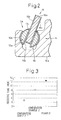
- the swash plate 8 is comprised of a swash plate substrate 18a made of a ferrous metal and sliding layers 18b, 18c formed on the front and rear surfaces of the swash plate substrate 18a.
- each of the front side and rear side shoes 9a, 9b is comprised of a shoe substrate 19a made of a ferrous material and coatings 19b, 19c made of resin coats formed on the flat part of the shoe substrate 19a sliding with the swash plate 8 and the spherical part sliding with the piston 6.
- each piston 6 is comprised of a piston substrate 16a made of an aluminum-based material and a coating 16b made of tin plating formed on the shoe seat of the piston substrate 16a.
- the ferrous material of the swash plate substrate 18a and the shoe substrates 19a is SUJ2 of the JIS.
- the sliding layers 18b, 18c are comprised of polytheretherketone (PEEK) in which is dispersed polytetrafluoroethylene (PTFE).
- PEEK polytheretherketone
- PTFE polytetrafluoroethylene
- the "resin coat” means a coating layer obtained by dispersing MoS 2 in PAI (polyamidimide).
- the aluminum-based material of the piston substrate 16a is an aluminum alloy containing about 10 wt% of silicon (Si).
- PAI polyamidimide
- MoS 2 molybdenum disulfide
- graphite graphite
- PAI polyamidimide
- PTFE polytetrafluoroethylene
- the seizure time (minutes) between the swash plate and shoes was found under conditions of a peripheral speed 10.4 m/sec and a load of 200 kg and no lubrication for the compressors of the example of the invention and Comparative Examples 1 and 2. The results are shown in FIG. 3.
- the sliding layers 18b, 18c are comprised of a binder made of PEEK in which a solid lubricant is dispersed, it is possible to achieve a high slidability performance under severe conditions. That is, in a compressor, where the trend is toward faster speeds, it is possible to achieve a high slidability performance due to the high heat resistance of polyetheretherketone regardless of the increase in heat due to high speed sliding.
Abstract
Description
- The present invention relates to a compressor used for a vehicle air-conditioning system etc.
- A refrigeration circuit used in a vehicle air-conditioning system includes a compressor for compressing a refrigerant gas. This compressor comes in various forms such as variable displacement types and fixed displacement types. More specifically, fixed displacement type compressors include not only single-headed piston type swash plate compressors, but also double-headed piston type swash plate compressors. Variable displacement type compressors also include not only single-headed piston type swash plate compressors, but also double-headed piston type swash plate compressors.
- Among these compressors, for example a single-headed piston type swash plate compressor defines and forms inside its housing cylinder bores, a crank chamber, a suction chamber, and a discharge chamber. Each cylinder bore accommodates a single-headed piston so that it may reciprocate. Further, a drive shaft supported rotatably by the housing is driven by an engine or another external drive source. The swash plate is supported by the drive shaft to be able to synchronously rotate with the drive shaft. A pair of shoes is accommodated in a pair of shoe seats, provided at an engagement portion in the piston, to drive the piston and a shoe is provided at each of the front and rear of the swash plate.
- If the swash plate is inclined at a certain angle with respect to the drive shaft, the compressor is a fixed displacement swash plate compressor. If the inclination angle of the swash plate is variable with respect to the drive shaft and the pressure in the crank chamber can be adjusted by a control valve to change the inclination angle and adjust the discharge capacity, it is a variable displacement swash plate compressor. On the other hand, if the piston is a single-headed piston having a head at only one of the front and rear of the swash plate, the compressor is a single-headed piston type swash plate compressor. If the piston is a double-headed piston having heads at both the front and rear of the swash plate, it is a double-headed piston type swash plate compressor.
- In this single-headed piston type swash plate compressor, if the drive shaft is driven by an external drive source, the swash plate synchronously rotates, so the pistons reciprocate in the cylinder bores through the shoes. Due to this, each cylinder bore forms a compression chamber with the head of the piston, so when the piston is in the suction stroke, low pressure refrigerant gas is sucked into the compression chamber from the suction chamber connected to an evaporator of the refrigeration circuit. When the piston is in the compression stroke, high pressure refrigerant gas is discharged to the discharge chamber from the compression chamber. This discharge chamber is connected to a condenser of the refrigeration circuit. The refrigeration circuit is used as a vehicle air-conditioning system for air-conditioning a vehicle.
- During this time, in the single-headed piston type swash plate compressor, the slidability of the sliding portions between the swash plate and the shoes and between other members is ensured by a mist of lubricating oil contained in the refrigerant gas. Further, it is also possible to form a sliding layer of a sprayed layer for improving the slidability at the sliding portions.
- In the above compressors of the related art, however, under severe conditions where the members slide at a high speed with respect to each other or where they slide at the time of a high heat load, the slidability of the sliding portions still was insufficient.
- An object of the present invention is to provide a compressor with sliding portions having a high slidability.
- According to the present invention, there is provided a compressor performing a compression action and having a sliding portion where one member slides with respect to another member, wherein the sliding portion is formed with a sliding layer including polyetheretherketone.
- Preferably, the sliding layer is comprised of a binder comprised of polyetheretherketone and a solid lubricant dispersed in the binder.
- Preferably, the compressor is provided with a swash plate and shoes sliding with the swash plate and sliding with pistons and the sliding layer is formed at least at one sliding portion of said shoes and pistons.
- Preferably, the compressor is a swash plate type compressor with the swash plate. The swash plate drives the piston by the shoes accommodated in the piston and thereby the piston performs the compression action. The shoes are formed with sliding portions between one shoe and the swash plate and between the other shoe and the piston and the sliding layer is formed on at least one sliding portion of said swash plate, said shoes and said pistons.
- Preferably, a housing of the compressor internally defines and forms cylinder bores, a crank chamber, a suction chamber and a discharge chamber. A drive shaft is rotatably supported by the housing and is driven by an external drive source. Further, the swash plate is supported by the drive shaft to be rotated with the drive shaft and the piston is accommodated in each of the cylinder bores to be able reciprocate therein and to define a compression chamber therein. Further, the swash plate is provided with a pair of shoes accommodated in a pair of shoe seats in the piston at the front and rear of the swash plate and drives the piston through the shoes accommodated in the piston and thereby the piston sucks refrigerant from the suction chamber and discharges compressed refrigerant into the discharge chamber. Further, the shoes are formed with sliding portions between one shoes and the swash plate and between the other shoe and the piston, and the sliding layer is formed on at least one sliding portion of said swash plate, said shoes and said pistons.
- These and other objects and features of the present invention will be more apparent from the following description, with reference to the accompanying drawings, wherein:
- FIG. 1 is a sectional view of a variable displacement single-headed piston type swash plate compressor according to an embodiment of the present invention;
- FIG. 2 is an enlarged sectional view of the principal parts of a variable displacement single-headed piston type swash plate compressor according to an embodiment of the present invention;
- FIG. 3 is graph of the seizure time of sliding portions in the compressors of the Examples and Comparative Examples 1 and 2 obtained from evaluations of performance.
-
- The inventors engaged in intensive research for solving the above problem and discovered that superior effects could be obtained if a sliding layer including polyetheretherketone is formed instead of a known sliding layer.
- That is, the compressor of the present invention is a compressor performing a compression action and having a sliding portion where one member slides with respect to another member, wherein the sliding portion is formed with a sliding layer including polyetheretherketone.
- In the compressor of the present invention, since the sliding layer includes polyetheretherketone, it is possible to achieve a high slidability performance at sliding portions even under severe conditions such as when one member slides against another member at a high speed or the members slide against each other at the time of a high heat load.
- There are various sliding portions in different compressors. For example, in a swash plate compressor provided with a swash plate and shoes sliding with the swash plate and sliding with the pistons, by forming the above sliding layer at least at part of the sliding portions of the swash plate, shoes, and pistons, the effects of the present invention can be realized.
- According to the discovery of the inventors, as described in Kogyo Zairyo (Industrial Materials, August 1988 Supplement (vol. 36, no. 12)), polyetheretherketone (PEEK) is extremely superior in heat resistance and is extremely tough. Therefore, a sliding layer including PEEK is considered to be able to achieve a higher slidability performance compared with a known sliding layer.
- The sliding layer is preferably comprised of a binder comprised of polyetheretherketone and a solid lubricant dispersed in the binder. As the solid lubricant, it is possible to employ molybdenum disulfide (MoS2), graphite, tungsten disulfide (WS2), boronitride (BN), polytetrafluoroethylene (PTFE), etc.
- To improve the abrasion resistance or to reduce the heat expansion coefficient, it is also possible to disperse carbon fiber or glass fiber etc. in the sliding layer. Further, it is also possible to form a sliding layer comprised of PEEK and a solid lubricant in a manner having continuous pores and impregnate the pores with a lubricating oil. By doing this, a higher slidability performance can be achieved.
- Next, a specific example of the present invention will be explained with reference to the drawings.
- In the variable displacement single-headed piston type swash plate compressor of the present example (hereinafter referred to simply as a "compressor"), as shown in FIG. 1, a
front housing 2 is connected to the front end of acylinder block 1. Acrank chamber 2a is formed between thecylinder block 1 and thefront housing 2. Arear housing 4 is connected to the rear end of thecylinder block 1 through avalve mechanism 3 comprised of suction valves, valve plate, discharge valves, and retainers. A suction chamber 4a and a discharge chamber 4b are formed in therear housing 4. The suction chamber 4a is connected to a not shown evaporator, the evaporator is connected through a not shown expansion valve to a not shown condenser, and the condenser is connected to the discharge chamber 4b. - The
drive shaft 5 is rotatably supported at thefront housing 2 and thecylinder block 1 throughbearings drive shaft 5 are formed in thecylinder block 1. A single-headedpiston 6 is accommodated in each cylinder bore 1a to be able to reciprocate therein. - A rotor 7 is fixed to the
drive shaft 5 and thedrive shaft 5 is able to rotate in thecrank chamber 2a through a bearing 2c adjacent to thefront housing 2. The swash plate 8 is oscillatingly provided adjacent to the rotor 7 through a pair of hinge mechanisms K. A throughhole 8a is formed in the swash plate 8. Thedrive shaft 5 is inserted through the throughhole 8a while allowing oscillating movement of the swash plate 8. A pair ofshoes pistons 6 are engaged with the swash plate 8 through a pair ofshoes shoes shoes shoes piston 6 to be accommodated therein. - Further, the
rear housing 4 houses acontrol valve 10 connected to the suction chamber 4a, the discharge chamber 4b, and thecrank chamber 2a. By adjusting the pressure in thecrank chamber 2a by thecontrol valve 10, it becomes possible to change the inclination angle of the swash plate 8 and to adjust the discharge capacity. - In the compressor of the above example, as shown in Fig. 2, the swash plate 8 is comprised of a
swash plate substrate 18a made of a ferrous metal and slidinglayers swash plate substrate 18a. Further, each of the front side andrear side shoes shoe substrate 19a made of a ferrous material andcoatings shoe substrate 19a sliding with the swash plate 8 and the spherical part sliding with thepiston 6. Further, eachpiston 6 is comprised of a piston substrate 16a made of an aluminum-based material and acoating 16b made of tin plating formed on the shoe seat of the piston substrate 16a. - Here, the ferrous material of the
swash plate substrate 18a and theshoe substrates 19a is SUJ2 of the JIS. The slidinglayers - As the sliding layer of the swash plate, use was made of polyamidimide (PAI) in which molybdenum disulfide (MoS2) and graphite are dispersed. The rest of the configuration is the same as that of the example of the invention.
- Further, as the sliding layer of the swash plate, use was made of polyamidimide (PAI) in which polytetrafluoroethylene (PTFE) is dispersed. The rest of the configuration is the same as that of the example of the invention.
- The seizure time (minutes) between the swash plate and shoes was found under conditions of a peripheral speed 10.4 m/sec and a load of 200 kg and no lubrication for the compressors of the example of the invention and Comparative Examples 1 and 2. The results are shown in FIG. 3.
- From FIG. 3, it is learned that in the compressor of the example of the invention, since the sliding
layers - While the invention has been described with reference to specific embodiment chosen for purpose of illustration, it should be apparent that numerous modifications could be made thereto by those skilled in the art without departing from the basic concept and scope of the invention.
Claims (5)
- A compressor performing a compression action and having a sliding portion where one member slides with respect to another member, wherein the sliding portion is formed with a sliding layer including polyetheretherketone.
- A compressor as set forth in claim 1, wherein the sliding layer is comprised of a binder comprised of polyetheretherketone and a solid lubricant dispersed in the binder.
- A compressor as set forth in claim 1 or 2, whereinthe compressor is provided with a swash plate and shoes sliding with the swash plate and sliding with pistons, andthe sliding layer is formed at least at one sliding portion of said swash plate, said shoes and said pistons.
- A compressor as set forth in claims 1 or 2, whereinthe compressor is a swash plate type compressor with a swash plate,the swash plate drives the piston by the shoes accommodated in the piston and thereby the piston performs the compression action,the shoes are formed with sliding portions between the shoes and the swash plate and between the shoes and the piston, andthe sliding layer is formed on at least one sliding portion of said swash plate, said shoes and said piston.
- A compressor as set forth in any one of claims 1 to 4, whereina housing of the compressor internally defines and forms cylinder bores, a crank chamber, a suction chamber and a discharge chamber,a drive shaft is rotatably supported by the housing and is driven by an external drive source,the swash plate is supported by the drive shaft to be rotated with the drive shaft,the piston is accommodated in each of the cylinder bores to be able reciprocate therein and to define a compression chamber therein,the swash plate is provided with a pair of shoes accommodated in a pair of shoe seats in the piston at the front and rear of the swash plate and drives the piston through the shoes accommodated in the piston and thereby the piston sucks refrigerant from the suction chamber and discharges compressed refrigerant into the discharge chamber,the shoes are formed with sliding portions between the shoes and the swash plate and between the shoes and the piston, andthe sliding layer is formed on at least one sliding portion of said swash plate, said shoes and said piston.
Applications Claiming Priority (2)
| Application Number | Priority Date | Filing Date | Title |
|---|---|---|---|
| JP2000225908A JP2002039062A (en) | 2000-07-26 | 2000-07-26 | Compressor |
| JP2000225908 | 2000-07-26 |
Publications (2)
| Publication Number | Publication Date |
|---|---|
| EP1176310A2 true EP1176310A2 (en) | 2002-01-30 |
| EP1176310A3 EP1176310A3 (en) | 2004-05-12 |
Family
ID=18719615
Family Applications (1)
| Application Number | Title | Priority Date | Filing Date |
|---|---|---|---|
| EP01117678A Withdrawn EP1176310A3 (en) | 2000-07-26 | 2001-07-26 | PEEK compressor coating |
Country Status (3)
| Country | Link |
|---|---|
| US (1) | US6584886B2 (en) |
| EP (1) | EP1176310A3 (en) |
| JP (1) | JP2002039062A (en) |
Cited By (3)
| Publication number | Priority date | Publication date | Assignee | Title |
|---|---|---|---|---|
| WO2006006697A1 (en) | 2004-07-09 | 2006-01-19 | Kabushiki Kaisha Toyota Jidoshokki | Sliding member of compressor |
| WO2006066827A1 (en) * | 2004-12-20 | 2006-06-29 | Knorr-Bremse Systeme für Nutzfahrzeuge GmbH | Dry running swashplate compressor comprising a coated swashplate |
| DE102008055948A1 (en) * | 2008-11-05 | 2010-05-06 | Bosch Mahle Turbo Systems Gmbh & Co. Kg | Loading device, particularly exhaust gas turbocharger for motor vehicle, comprises axle mounted in bearing housing, compressor wheel and turbine wheel |
Families Citing this family (17)
| Publication number | Priority date | Publication date | Assignee | Title |
|---|---|---|---|---|
| JP4631228B2 (en) * | 2001-07-31 | 2011-02-16 | 株式会社豊田自動織機 | Vibration isolation structure in piston type compressor |
| JP2003049766A (en) * | 2001-08-03 | 2003-02-21 | Toyota Industries Corp | Sliding part and compressor |
| JP2003278742A (en) * | 2002-03-26 | 2003-10-02 | Daido Metal Co Ltd | Both surface sliding thrust bearing |
| DE10223844B4 (en) * | 2002-05-28 | 2013-04-04 | Danfoss A/S | Water hydraulic machine |
| US20070081904A1 (en) * | 2003-09-02 | 2007-04-12 | Hajime Kurita | Variable displacement type compressor |
| JP2005171953A (en) * | 2003-12-15 | 2005-06-30 | Honda Motor Co Ltd | Rotation fluid machine |
| KR100633044B1 (en) | 2004-07-26 | 2006-10-12 | 한국기계연구원 | Sliding construction of hydraulic power pump |
| KR101261110B1 (en) | 2008-10-27 | 2013-05-06 | 다이호 고교 가부시키가이샤 | Ptfe series sliding material, bearing, and ptfe series sliding material manufacturing method |
| CN103404008B (en) * | 2011-01-27 | 2016-06-08 | 株式会社电装 | The carbon brush of petrolift and manufacture method thereof |
| JP5841471B2 (en) * | 2012-03-26 | 2016-01-13 | 大豊工業株式会社 | Swash plate |
| JP6230803B2 (en) | 2013-04-10 | 2017-11-15 | Ntn株式会社 | Swash plate compressor hemispherical shoe and swash plate compressor |
| US20150285230A1 (en) * | 2014-04-07 | 2015-10-08 | Halla Visteon Climate Control Corp. | Seal structure for a rotary valve compressor |
| US10598167B2 (en) | 2014-07-23 | 2020-03-24 | Ntn Corporation | Semispherical shoe for swash plate compressor and swash plate compressor |
| US10670074B2 (en) | 2014-08-22 | 2020-06-02 | Ntn Corporation | Method for producing semispherical shoe for swash plate compressor and injection molding die |
| JP6466754B2 (en) * | 2015-03-24 | 2019-02-06 | Ntn株式会社 | Swash plate compressor hemispherical shoe and swash plate compressor |
| JP6571960B2 (en) * | 2015-03-24 | 2019-09-04 | Ntn株式会社 | Swash plate compressor hemispherical shoe and swash plate compressor |
| EP4239184B1 (en) * | 2022-03-02 | 2024-04-24 | Danfoss A/S | Piston of a hydraulic piston machine |
Citations (7)
| Publication number | Priority date | Publication date | Assignee | Title |
|---|---|---|---|---|
| GB2161242A (en) * | 1984-07-07 | 1986-01-08 | Bendix Ltd | Seal/bearing member for piston |
| US4629200A (en) * | 1983-08-04 | 1986-12-16 | Ae Plc | Non-metallic piston rings with controlled expansion pressure |
| US4724746A (en) * | 1984-02-10 | 1988-02-16 | Ae Plc | Tilting bearing pads for improved lubrication |
| EP0353462A1 (en) * | 1988-07-21 | 1990-02-07 | Elring Dichtungswerke GmbH | Pistons, particularly plunger pistons for compressors |
| EP0794330A2 (en) * | 1996-03-05 | 1997-09-10 | Fmc Corporation | Cam follower retainer for a swashplate pump |
| US5743707A (en) * | 1995-11-24 | 1998-04-28 | Asea Brown Boveri Ag | Contact seal for turbomachines running at high speed and/or having high temperatures in the sealing region |
| EP0933566A1 (en) * | 1998-02-02 | 1999-08-04 | Maschinenfabrik Sulzer-Burckhardt AG | Sealing for dry-running piston compressor |
Family Cites Families (7)
| Publication number | Priority date | Publication date | Assignee | Title |
|---|---|---|---|---|
| DE4424670B4 (en) * | 1994-07-13 | 2005-11-03 | Danfoss A/S | Hydraulic piston machine |
| JP3642077B2 (en) | 1995-01-27 | 2005-04-27 | 大豊工業株式会社 | Swash plate compressor swash plate |
| JP3039762B2 (en) * | 1995-03-07 | 2000-05-08 | 株式会社豊田自動織機製作所 | Reciprocating compressor |
| JPH09209926A (en) | 1996-01-29 | 1997-08-12 | Calsonic Corp | Swash plate type compressor |
| JPH11193781A (en) * | 1997-12-26 | 1999-07-21 | Toyota Autom Loom Works Ltd | Variable capacity type compression machine |
| JP2000257555A (en) * | 1999-03-08 | 2000-09-19 | Toyota Autom Loom Works Ltd | Compressor |
| JP4001257B2 (en) * | 1999-03-17 | 2007-10-31 | 株式会社豊田自動織機 | Compressor |
-
2000
- 2000-07-26 JP JP2000225908A patent/JP2002039062A/en active Pending
-
2001
- 2001-07-18 US US09/908,127 patent/US6584886B2/en not_active Expired - Fee Related
- 2001-07-26 EP EP01117678A patent/EP1176310A3/en not_active Withdrawn
Patent Citations (7)
| Publication number | Priority date | Publication date | Assignee | Title |
|---|---|---|---|---|
| US4629200A (en) * | 1983-08-04 | 1986-12-16 | Ae Plc | Non-metallic piston rings with controlled expansion pressure |
| US4724746A (en) * | 1984-02-10 | 1988-02-16 | Ae Plc | Tilting bearing pads for improved lubrication |
| GB2161242A (en) * | 1984-07-07 | 1986-01-08 | Bendix Ltd | Seal/bearing member for piston |
| EP0353462A1 (en) * | 1988-07-21 | 1990-02-07 | Elring Dichtungswerke GmbH | Pistons, particularly plunger pistons for compressors |
| US5743707A (en) * | 1995-11-24 | 1998-04-28 | Asea Brown Boveri Ag | Contact seal for turbomachines running at high speed and/or having high temperatures in the sealing region |
| EP0794330A2 (en) * | 1996-03-05 | 1997-09-10 | Fmc Corporation | Cam follower retainer for a swashplate pump |
| EP0933566A1 (en) * | 1998-02-02 | 1999-08-04 | Maschinenfabrik Sulzer-Burckhardt AG | Sealing for dry-running piston compressor |
Cited By (5)
| Publication number | Priority date | Publication date | Assignee | Title |
|---|---|---|---|---|
| WO2006006697A1 (en) | 2004-07-09 | 2006-01-19 | Kabushiki Kaisha Toyota Jidoshokki | Sliding member of compressor |
| EP1785627A1 (en) * | 2004-07-09 | 2007-05-16 | Kabushiki Kaisha Toyota Jidoshokki | Sliding member of compressor |
| EP1785627A4 (en) * | 2004-07-09 | 2012-07-11 | Toyota Jidoshokki Kk | Sliding member of compressor |
| WO2006066827A1 (en) * | 2004-12-20 | 2006-06-29 | Knorr-Bremse Systeme für Nutzfahrzeuge GmbH | Dry running swashplate compressor comprising a coated swashplate |
| DE102008055948A1 (en) * | 2008-11-05 | 2010-05-06 | Bosch Mahle Turbo Systems Gmbh & Co. Kg | Loading device, particularly exhaust gas turbocharger for motor vehicle, comprises axle mounted in bearing housing, compressor wheel and turbine wheel |
Also Published As
| Publication number | Publication date |
|---|---|
| JP2002039062A (en) | 2002-02-06 |
| US20020025259A1 (en) | 2002-02-28 |
| US6584886B2 (en) | 2003-07-01 |
| EP1176310A3 (en) | 2004-05-12 |
Similar Documents
| Publication | Publication Date | Title |
|---|---|---|
| US6584886B2 (en) | Compressor | |
| US6752065B2 (en) | Sliding member and sliding device | |
| US5943941A (en) | Reciprocating compressor | |
| US6582200B2 (en) | Swash plate compressor having shoes made of a magnesium-based material | |
| US6581507B2 (en) | Single-headed piston type swash plate compressor | |
| US6589021B2 (en) | Single-headed piston type swash plate compressor | |
| EP1167761A2 (en) | Swash plate type compressor | |
| US6568918B2 (en) | Lubrication coating for the sliding portion of a swashplate compressor | |
| US6666128B2 (en) | Swash plate in swash plate type compressor | |
| US20020046647A1 (en) | Compressors | |
| EP1074737A2 (en) | Lubrication layer of piston seat of a swash-plate refrigerant compressor | |
| JPH09209926A (en) | Swash plate type compressor | |
| US20020046646A1 (en) | Compressors | |
| JP6406339B2 (en) | Swash plate compressor | |
| EP1236897B1 (en) | Compressor coating | |
| JP2002089440A (en) | One side swash plate compressor | |
| JP2002089441A (en) | Unilateral swash plate type compressor | |
| JP2002089439A (en) | Swash plate compressor | |
| EP1188923A2 (en) | Coating for a swash plate of a swash plate compressor | |
| KR20010111692A (en) | Surface management of swash plate and piston in compressor for vehicle | |
| KR20010111693A (en) | Surface coating structure of compressor for vehicle |
Legal Events
| Date | Code | Title | Description |
|---|---|---|---|
| PUAI | Public reference made under article 153(3) epc to a published international application that has entered the european phase |
Free format text: ORIGINAL CODE: 0009012 |
|
| 17P | Request for examination filed |
Effective date: 20010726 |
|
| AK | Designated contracting states |
Kind code of ref document: A2 Designated state(s): AT BE CH CY DE DK ES FI FR GB GR IE IT LI LU MC NL PT SE TR |
|
| AX | Request for extension of the european patent |
Free format text: AL;LT;LV;MK;RO;SI |
|
| PUAL | Search report despatched |
Free format text: ORIGINAL CODE: 0009013 |
|
| AK | Designated contracting states |
Kind code of ref document: A3 Designated state(s): AT BE CH CY DE DK ES FI FR GB GR IE IT LI LU MC NL PT SE TR |
|
| AX | Request for extension of the european patent |
Extension state: AL LT LV MK RO SI |
|
| STAA | Information on the status of an ep patent application or granted ep patent |
Free format text: STATUS: THE APPLICATION IS DEEMED TO BE WITHDRAWN |
|
| 18D | Application deemed to be withdrawn |
Effective date: 20040203 |