EP1176296A1 - Stratified scavenging two-stroke cycle engine - Google Patents
Stratified scavenging two-stroke cycle engine Download PDFInfo
- Publication number
- EP1176296A1 EP1176296A1 EP00912907A EP00912907A EP1176296A1 EP 1176296 A1 EP1176296 A1 EP 1176296A1 EP 00912907 A EP00912907 A EP 00912907A EP 00912907 A EP00912907 A EP 00912907A EP 1176296 A1 EP1176296 A1 EP 1176296A1
- Authority
- EP
- European Patent Office
- Prior art keywords
- air
- port
- scavenging
- piston
- suction port
- Prior art date
- Legal status (The legal status is an assumption and is not a legal conclusion. Google has not performed a legal analysis and makes no representation as to the accuracy of the status listed.)
- Granted
Links
Images


Classifications
-
- F—MECHANICAL ENGINEERING; LIGHTING; HEATING; WEAPONS; BLASTING
- F02—COMBUSTION ENGINES; HOT-GAS OR COMBUSTION-PRODUCT ENGINE PLANTS
- F02F—CYLINDERS, PISTONS OR CASINGS, FOR COMBUSTION ENGINES; ARRANGEMENTS OF SEALINGS IN COMBUSTION ENGINES
- F02F1/00—Cylinders; Cylinder heads
- F02F1/18—Other cylinders
- F02F1/22—Other cylinders characterised by having ports in cylinder wall for scavenging or charging
-
- F—MECHANICAL ENGINEERING; LIGHTING; HEATING; WEAPONS; BLASTING
- F02—COMBUSTION ENGINES; HOT-GAS OR COMBUSTION-PRODUCT ENGINE PLANTS
- F02B—INTERNAL-COMBUSTION PISTON ENGINES; COMBUSTION ENGINES IN GENERAL
- F02B25/00—Engines characterised by using fresh charge for scavenging cylinders
- F02B25/14—Engines characterised by using fresh charge for scavenging cylinders using reverse-flow scavenging, e.g. with both outlet and inlet ports arranged near bottom of piston stroke
- F02B25/16—Engines characterised by using fresh charge for scavenging cylinders using reverse-flow scavenging, e.g. with both outlet and inlet ports arranged near bottom of piston stroke the charge flowing upward essentially along cylinder wall opposite the inlet ports
-
- F—MECHANICAL ENGINEERING; LIGHTING; HEATING; WEAPONS; BLASTING
- F02—COMBUSTION ENGINES; HOT-GAS OR COMBUSTION-PRODUCT ENGINE PLANTS
- F02B—INTERNAL-COMBUSTION PISTON ENGINES; COMBUSTION ENGINES IN GENERAL
- F02B25/00—Engines characterised by using fresh charge for scavenging cylinders
- F02B25/20—Means for reducing the mixing of charge and combustion residues or for preventing escape of fresh charge through outlet ports not provided for in, or of interest apart from, subgroups F02B25/02 - F02B25/18
- F02B25/22—Means for reducing the mixing of charge and combustion residues or for preventing escape of fresh charge through outlet ports not provided for in, or of interest apart from, subgroups F02B25/02 - F02B25/18 by forming air cushion between charge and combustion residues
-
- F—MECHANICAL ENGINEERING; LIGHTING; HEATING; WEAPONS; BLASTING
- F02—COMBUSTION ENGINES; HOT-GAS OR COMBUSTION-PRODUCT ENGINE PLANTS
- F02B—INTERNAL-COMBUSTION PISTON ENGINES; COMBUSTION ENGINES IN GENERAL
- F02B33/00—Engines characterised by provision of pumps for charging or scavenging
- F02B33/02—Engines with reciprocating-piston pumps; Engines with crankcase pumps
- F02B33/04—Engines with reciprocating-piston pumps; Engines with crankcase pumps with simple crankcase pumps, i.e. with the rear face of a non-stepped working piston acting as sole pumping member in co-operation with the crankcase
-
- F—MECHANICAL ENGINEERING; LIGHTING; HEATING; WEAPONS; BLASTING
- F02—COMBUSTION ENGINES; HOT-GAS OR COMBUSTION-PRODUCT ENGINE PLANTS
- F02B—INTERNAL-COMBUSTION PISTON ENGINES; COMBUSTION ENGINES IN GENERAL
- F02B75/00—Other engines
- F02B75/16—Engines characterised by number of cylinders, e.g. single-cylinder engines
-
- F—MECHANICAL ENGINEERING; LIGHTING; HEATING; WEAPONS; BLASTING
- F02—COMBUSTION ENGINES; HOT-GAS OR COMBUSTION-PRODUCT ENGINE PLANTS
- F02B—INTERNAL-COMBUSTION PISTON ENGINES; COMBUSTION ENGINES IN GENERAL
- F02B1/00—Engines characterised by fuel-air mixture compression
- F02B1/02—Engines characterised by fuel-air mixture compression with positive ignition
- F02B1/04—Engines characterised by fuel-air mixture compression with positive ignition with fuel-air mixture admission into cylinder
-
- F—MECHANICAL ENGINEERING; LIGHTING; HEATING; WEAPONS; BLASTING
- F02—COMBUSTION ENGINES; HOT-GAS OR COMBUSTION-PRODUCT ENGINE PLANTS
- F02B—INTERNAL-COMBUSTION PISTON ENGINES; COMBUSTION ENGINES IN GENERAL
- F02B17/00—Engines characterised by means for effecting stratification of charge in cylinders
-
- F—MECHANICAL ENGINEERING; LIGHTING; HEATING; WEAPONS; BLASTING
- F02—COMBUSTION ENGINES; HOT-GAS OR COMBUSTION-PRODUCT ENGINE PLANTS
- F02B—INTERNAL-COMBUSTION PISTON ENGINES; COMBUSTION ENGINES IN GENERAL
- F02B75/00—Other engines
- F02B75/02—Engines characterised by their cycles, e.g. six-stroke
- F02B2075/022—Engines characterised by their cycles, e.g. six-stroke having less than six strokes per cycle
- F02B2075/025—Engines characterised by their cycles, e.g. six-stroke having less than six strokes per cycle two
-
- F—MECHANICAL ENGINEERING; LIGHTING; HEATING; WEAPONS; BLASTING
- F02—COMBUSTION ENGINES; HOT-GAS OR COMBUSTION-PRODUCT ENGINE PLANTS
- F02M—SUPPLYING COMBUSTION ENGINES IN GENERAL WITH COMBUSTIBLE MIXTURES OR CONSTITUENTS THEREOF
- F02M35/00—Combustion-air cleaners, air intakes, intake silencers, or induction systems specially adapted for, or arranged on, internal-combustion engines
- F02M35/10—Air intakes; Induction systems
- F02M35/1015—Air intakes; Induction systems characterised by the engine type
- F02M35/1019—Two-stroke engines; Reverse-flow scavenged or cross scavenged engines
-
- F—MECHANICAL ENGINEERING; LIGHTING; HEATING; WEAPONS; BLASTING
- F02—COMBUSTION ENGINES; HOT-GAS OR COMBUSTION-PRODUCT ENGINE PLANTS
- F02M—SUPPLYING COMBUSTION ENGINES IN GENERAL WITH COMBUSTIBLE MIXTURES OR CONSTITUENTS THEREOF
- F02M35/00—Combustion-air cleaners, air intakes, intake silencers, or induction systems specially adapted for, or arranged on, internal-combustion engines
- F02M35/10—Air intakes; Induction systems
- F02M35/104—Intake manifolds
- F02M35/108—Intake manifolds with primary and secondary intake passages
Definitions
- the present invention relates to a stratified scavenging two-stroke cycle engine, and more particularly to a piston valve type stratified scavenging two-stroke cycle engine which separately sucks an air-fuel mixture and a leading air for scavenging.
- Figs. 12 and 13 shows one structural embodiment of the stratified scavenging two-stroke cycle engine described in WO98/57053.
- a piston 4 is provided so as to be slidably and in a sealing manner inserted within a cylinder 3.
- the piston 4 is connected to a crank 5 within a crank chamber 11 via a connecting rod 6.
- a space portion in which a capacity above the piston 4 within the cylinder 3 changes forms a cylinder chamber 10.
- Two scavenging flow passages 20 and 20 communicating the cylinder chamber 10 with the crank chamber 11 are provided on both side surfaces of the cylinder 3.
- the respective scavenging flow passages 20 and 20 are open as scavenging ports 21 and 21 to the cylinder chamber 10.
- An exhaust port 22 is provided in an axial direction of the cylinder 3 and at a position in a top dead center side of the piston 4 rather than the scavenging ports 21 and 21, in the cylinder 3. Further, an air-fuel mixture suction port 23 and leading air suction ports 24 and 24 disposed in both sides of the air-fuel mixture port 23 are provided on an inner peripheral surface of the cylinder 3. A through hole 31 is provided in a lower portion of the piston 4. Piston grooves 25 and 25 respectively communicating the leading air suction ports 24 and 24 with the scavenging ports 21 and 21 in correspondence to a vertical motion of the piston 4 are provided on right and left outer peripheral surfaces with respect to the through hole 31.
- an interval between two leading air suction ports 24 and 24, that is, an interval K between the piston grooves 25 and 25 is set to be larger than a width M of the air-fuel mixture suction port 23.
- the air is sucked within the crank chamber 11 from the leading air suction ports 24 and 24 via the scavenging flow passages 20 and 20.
- inner portions of the scavenging flow passages 20 and 20 become in a state of being full of the air.
- the exhaust port 22 and the scavenging ports 21 and 21 become sequentially in a state of being opened to the cylinder chamber 10, and a combustion gas is at first discharged from the exhaust port 22.
- the air stored within the scavenging flow passages 20 and 20 is injected out within the cylinder chamber 10 from the scavenging ports 21 and 21 due to the increased pressure within the crank chamber 11. Accordingly, the combustion gas left within the cylinder chamber 10 is expelled from the exhaust port 22 into an atmospheric air via a muffler (not shown).
- the air-fuel mixture within the crank chamber 11 is charged within the cylinder chamber 10 via the scavenging flow passages 20 and 20 and the exhaust ports 21 and 21.
- the piston 4 starts moving upward from the bottom dead center, whereby the pressure within the crank chamber 11 starts reducing, and the scavenging port 21 and the exhaust port 22 are sequentially closed, so that the cycle mentioned above is again repeated.
- an air control valve for adjusting an air supply amount is provided in an upstream side of the leading air suction port.
- Japanese Utility Model Publication No. 55-4518 there has been known Japanese Utility Model Publication No. 55-4518.
- Fig. 15 shows one structural embodiment of a stratified scavenging two-stroke cycle engine described in Japanese Utility Model Publication No. 55-4518
- Fig. 16 is a cross sectional view along a line 16-16 in Fig. 15.
- a carburetor 50 having a suction air throttle valve 51 is provided in the air-fuel mixture suction port 23 open to the crank chamber 11.
- a two-forked branch pipe 61 attached to an air supply pipe 60 and branched into two air supply passages 62 and 62 is attached to the cylinder 3.
- the air supply passages 62 and 62 of the branch pipe 61 are communicated with the scavenging ports 21 and 21 open to the cylinder chamber 10.
- Check valves 65 and 65 are respectively provided in the air supply passages 62 and 62.
- An air control valve 63 having a butterfly type variable valve 64 is provided in the air supply pipe 60.
- the variable valve 64 is structured such as to be connected to the suction air throttle valve 51 of the carburetor 50 by a rod 52 so as to interlock therewith.
- An exhaust port 22 is provided on an opposing surface of the air supply pipe 60 of the cylinder 3.
- the air control valve 63 is operated interlocking with the suction air throttle valve 51 in the carburetor 50, is set so that 0 or a fine amount is supplied at a time when the engine is under idling or under a low load operation, and an air at an amount corresponding to an operation condition is supplied at the other operation times.
- the air-fuel mixture suction port 23 In order to increase a suction efficiency of the air-fuel mixture, it is necessary to form the air-fuel mixture suction port 23 to be equal to or more than a predetermined area. Further, in the same manner, in order to increase a suction efficiency and a scavenging efficiency of the leading air, it is necessary to form the scavenging ports 21 and 21 and the piston grooves 25 and 25 to be equal to or more than a predetermined area. Accordingly, although a detailed description is not given in WO98/57053, the air-fuel mixture suction port 23, the scavenging ports 21 and 21 and the piston grooves 25 and 25 actually occupy a very large area, as shown in Fig. 17.
- the interval K between two leading air suction ports'24 and 24 is larger than the width M of the air-fuel mixture suction port 23. Accordingly, a width N of the leading air suction ports 24 and 24 positioned so as to be gripped between the air-fuel mixture suction port 23 and the scavenging ports 21 and 21 is reduced. Accordingly, the area of the leading air suction ports 24 and 24 is reduced, and there is generated a problem that a suction efficiency of the leading air is deteriorated.
- the air supply pipe 60 having the air control valve 63 is attached to the cylinder 3 via the branch pipe 61, a number of the parts is increased, the structure is complex and a placing space is large. Accordingly, in the case that a product is constituted by using the engine, it becomes hard to assemble a whole of the structure in a compact manner, so that there are problems that a general purpose property is deteriorated and a cost is increased.
- Fig. 18 is a side elevational schematic view of the cylinder 3 which describes an embodiment structured in the manner mentioned above.
- an interval R between two leading air suction ports 24 and 24 is set to be smaller than a width S of the air-fuel mixture suction port 23. Accordingly, it is possible to increase a width T of the leading air suction ports 24 and 24, and it is possible to set an area thereof to be sufficiently large.
- the present invention is made by paying attention to the problems mentioned above, and an object of the present invention is to provide a stratified scavenging two-stroke cycle engine which can improve a leading air suction efficiency, can make a piston compact, has a simple structure, has a reduced number of parts, has a small placing space and has a low cost.
- a stratified scavenging two-stroke cycle engine comprising an exhaust port and a scavenging port which are connected to a cylinder chamber of an engine, a leading air suction port not connected to the cylinder chamber and a crank chamber in all of strokes of a piston, an air-fuel mixture suction port connected to the crank chamber, a scavenging flow passage connecting between the scavenging port and the crank chamber, a piston groove connecting between the leading air suction port and the scavenging port and not connecting between the air-fuel mixture suction port and the scavenging port at a time of a suction stroke, and provided in an outer peripheral portion of the piston; and the leading air suction port, the air-fuel mixture suction port and the scavenging port being opened and closed due to a vertical motion of the piston, wherein the leading air suction port is positioned at an opposite side to the air-fuel mixture suction port with respect to an axis of the cylinder.
- the position of the leading air suction port is set to be opposite side to that of the air-fuel mixture suction port, it is possible to sufficiently secure an opening area of the leading air suction port even when the length of the piston is short. Accordingly, it is possible to obtain the stratified scavenging two-stroke cycle engine which has an improved leading air suction efficiency, is compact and light, has a small placing space and has a low cost.
- the two-stroke cycle engine is structured such that the piston groove is not connected to the exhaust port at a top dead center, and an upper edge of the piston groove is positioned in a side of a cylinder head in a direction of the cylinder axis rather than a lower edge of the exhaust port within a range not overlapping in the direction of the cylinder axis with a width portion in a piston peripheral direction of the exhaust port.
- the structure may be made such that the two-stroke cycle engine further comprises an air control valve arranged close to the leading air suction port and adjusting a suction air amount.
- the two-stroke cycle may be structured such that a valve body of the air control valve is integrally formed with the cylinder.
- Fig. 18 is a side elevational schematic view of a cylinder describing a structural embodiment in which an air-fuel mixture suction port and two leading air suction ports are provided so as to be shifted to each other in a direction of a cylinder axis at a predetermined distance.
- Fig. 1 is a front elevational cross sectional view in a piston top dead center of a stratified scavenging two-stroke cycle engine 1 in accordance with a first embodiment
- Fig. 2 is a side elevational cross sectional view.
- a piston 4 is closely and slidably inserted to a cylinder 3 attached to an upper side of a crank case 2.
- a crank 5 and the piston 4 which are rotatably attached to the crank case 2 are connected by a connecting rod 6.
- a space portion having a variable capacity and disposed in an upper side of the piston 4 within the cylinder 3 forms a cylinder chamber 10.
- a space portion disposed in a lower side of the piston 4 and surrounded by the cylinder 3 and the crank case 2 forms a crank chamber 11.
- a cylinder head 7 is provided in an upper portion of the cylinder 3.
- An exhaust port 22 and a leading air suction port 24 are provided in one side of an inner peripheral surface of the cylinder 3, and an air-fuel mixture suction port 23 is provided in another side.
- scavenging flow passages 20 and 20 connecting the cylinder chamber 10 to the crank chamber 11 are respectively provided on both side surfaces of the cylinder 3.
- the scavenging flow passages 20 and 20 are structured such that connection portions to the cylinder chamber 10 are open to the inner peripheral surface of the cylinder 3 so as to form scavenging ports 21 and 21. In this case, in Fig.
- the leading air suction port 24 and the exhaust port 22 are provided in an opposite side to the air-fuel mixture suction port 23 with respect to a center axis (an axis) P of the cylinder 3.
- Two scavenging ports 21 and 21 in both sides are respectively provided at positions forming an angle 90 degrees with respect to the air-fuel mixture suction port 23 and the leading air suction port 24.
- Two pistons 25 and 25 provided on the outer peripheral surfaces in both sides of the piston 4 are provided at positions connecting the scavenging port 21 to the leading air suction port 24.
- the position of the scavenging port 21 is not always limited to the position at 90 degrees, and can be suitably selected in correspondence to a positional relation between the leading air suction port 24 and the exhaust port 22, and may be asymmetrical. Further, the number of the scavenging ports 21 is not limited to two.
- Fig. 4 corresponds to a development in a cross section along a line 4-4 in Fig. 3, and shows a mutual positional relation among the scavenging port 21, the exhaust port 22, the air-fuel mixture suction port 23, the leading air suction port 24 and the piston grooves 25 and 25 at the piston top dead center position. That is, the piston grooves 25 and 25 are not connected to the exhaust port 22 and the air-fuel mixture port 23 at the piston top dead center position, and connects the scavenging port 21 to the leading air suction port 24. Then, a piston groove upper edge 25a is positioned in a side of the cylinder head 7 at a distance G in the axial direction of the piston 4 rather than an exhaust port lower edge 22a.
- a leading air suction port upper edge 24a is positioned in a side of the crank chamber 11 at a distance H in the axial direction of the piston 4 rather than the exhaust port lower edge 22a. Accordingly, it is possible to reduce an interval E between two leading air suction ports 24 and 24 provided in right and left sides around the exhaust port 22, and it is possible to increase a width F of the leading air suction port 24 so as to increase a leading air suction area. Further, since the piston groove upper edge 25a is positioned in the side of the cylinder head 7 at the distance G rather than the exhaust port lower edge 22a, it is possible to increase a size J in the cylinder axial direction of the piston groove 25 even when reducing an axial length L of the cylinder 3. In this case, the piston groove 25 is provided at a position not being connected to the air-fuel mixture suction port 23 between the piston top dead center position and the piston bottom dead center position shown by a two-dot chain line.
- Fig. 5 is a schematic view showing a positional relation of the respective ports at the piston bottom dead center position corresponding to a final stroke of an explosion and an exhaust at which the piston 4 moves downward.
- the scavenging port 21 and the exhaust port 22 are connected to the cylinder chamber 10.
- the piston upper edge 4a is positioned close to the exhaust port lower edge 22a.
- the leading air suction port 24 is closed by the piston 4, and the leading air suction port 24 and the scavenging port 21 are not connected.
- the scavenging port 21 is connected to the crank chamber 11 via the scavenging flow passage 20, and the air-fuel mixture suction port 23 is closed by the piston 4.
- the exhaust gas is discharged from the exhaust port 22 due to the leading air pressed out from the scavenging port 21.
- the air-fuel mixture in the crank chamber 11 is supplied to the cylinder chamber 10 from the scavenging port 21 through the scavenging flow passage 20.
- Fig. 6 shows a positional relation of the respective ports at the middle stroke of the compression and the suction at which the piston 4 moves upward, and shows a state that the piston 25 starts connecting to the leading air suction port 24. That is, the exhaust port 22 and the scavenging port 21 are closed by the piston 4.
- the piston groove upper edge 25a is at the position of the scavenging port lower edge 21a, and the leading air suction port 24 and the scavenging port 21 are in a state of starting connecting via the piston groove 25.
- the piston lower edge 4b is at the position of the air-fuel mixture suction port lower edge 23a, and in a state of starting sucking the air-fuel mixture.
- the air-fuel mixture in the cylinder chamber 10 is compressed, and an internal pressure of the crank chamber 11 is reduced.
- the timings of opening and closing the leading air suction port 24 and the air-fuel mixture suction port 23 are set to be simultaneous, however, it is not necessary to always set to be simultaneous.
- the positions of the leading air suction ports 24 and 24 are set to be opposite side to the air-fuel mixture suction port 23, it is possible to increase the opening area of the leading air suction ports 24 and 24 in spite that the length of the piston 4 is short.
- the piston groove upper edge 25a within the range not overlapping in the cylinder axial direction with the width portion in the piston peripheral direction of the exhaust port 22 is positioned in the side of the cylinder head 7 in the cylinder axial direction rather than the exhaust port lower edge 22a. Accordingly, it is possible to increase the size J in the cylinder axial direction of the piston groove 25.
- the cross sectional area of the piston groove 25, that is, the leading air passing area
- the length of the piston 4 can be made the same as the conventional one even when increasing the area of the leading air suction port 24, it is possible to make the structure compact and light, and it is possible to obtain the stratified scavenging two-stroke cycle engine 1 having a reduced cost.
- Fig. 8 is a front elevational cross sectional view of a stratified scavenging two-stroke cycle engine 1 provided with an air control valve in accordance with a second embodiment
- Fig. 9 is a cross sectional view along a line 9-9 in Fig. 8.
- the same reference numerals are attached to the same elements as those shown in Fig. 1, a description will be omitted and a description will be given of only different parts.
- a carburetor 50 having an air throttle valve 51 is arranged in an upstream side of an air-fuel mixture suction port 23.
- a rotary valve type air control valve 30 is attached to a portion in an inlet port of a leading air suction passage 26 communicating with a leading air suction port 24 of a cylinder 3 and below an exhaust pipe 27 connecting to an exhaust port 22.
- a stepped cylindrical hole 32 is provided in a valve body 31 of the air control valve 30, and a rotary valve 40 is rotatably inserted to the stepped cylindrical hole 32.
- An air intake port 34 communicating with the stepped cylindrical hole 32 is provided at an end portion in a side of a stepped portion 33 of the stepped cylindrical hole 32, and is connected to an air cleaner (not shown) via a suction pipe (not shown).
- An air discharge port 36 connecting the stepped cylinder hole 32 to the leading air suction passage 26 is provided on a mounting surface 35 of the valve body 31 to the cylinder 3.
- a flange 37 is provided in the valve body 31, and is fastened to the cylinder 3 by a bolt 38.
- An air communication hole 41 communicating with the air intake port 34 is provided in the rotary valve 40. Further, a communication hole 42 rotating so as to open and close the communication passage between the air communication hole 41 and the leading air suction passage 26 is provided on a wall surface of the rotary valve 40.
- Fig. 10 corresponding to a cross sectional view along a line 10-10 in Fig. 9 shows a state that the valve is opened.
- the air discharge port 36 provided in the valve body 31 is formed in a rectangular shape, on the contrary, the communication hole 42 provided in the rotary valve 40 is formed in a meniscus shape. Accordingly, in the case of rotating the rotary valve 40 from a closed position to an open position, the passage gradually starts opening from a top portion V of a circular arc, and can gradually increase the passage area.
- a lever 43 (refer to Fig. 9) provided in one end portion of the rotary valve 40 is connected to the air throttle valve 51 (refer to Fig. 8) of the carburetor 50 by a link apparatus (not shown) so as to interlock therewith.
- the rotary valve type air control valve 30 is arranged close to the leading air suction port 24. Accordingly, it is possible to supply a predetermined amount of leading air in correspondence to the engine load, the structure can be made compact, simple and light, the structure can be made compact in the case of constituting the product, and it is possible to obtain a low cost stratified scavenging two-stroke cycle engine 1.
- Fig. 11 is a cross sectional view of a main portion of a stratified scavenging two-stroke cycle engine 1 provided with an air control valve 30a in accordance with a third embodiment.
- a valve body 31a integrally formed with a cylinder 3 is provided in a terminal portion of a leading air suction passage 26 in the cylinder 3.
- a rotary valve 40 is rotatably inserted to a stepped cylindrical hole 32 pierced in the valve body 31a. Since structures and operations of the other members are the same as that of the air control valve 30 in accordance with the second embodiment, a description thereof will be omitted.
- valve body 31a is integrally structured with the cylinder 3
- the number of the parts is reduced and a simple structure can be obtained, so that the structure can be made more compact and the cost can be reduced.
- the present invention is useful for the stratified scavenging two-stroke cycle engine which can improve a suction efficiency of the leading air, make the piston compact, and has a simple structure and a low cost.
Landscapes
- Engineering & Computer Science (AREA)
- Chemical & Material Sciences (AREA)
- Combustion & Propulsion (AREA)
- Mechanical Engineering (AREA)
- General Engineering & Computer Science (AREA)
- Combustion Methods Of Internal-Combustion Engines (AREA)
- Cylinder Crankcases Of Internal Combustion Engines (AREA)
Abstract
Description
- The present invention relates to a stratified scavenging two-stroke cycle engine, and more particularly to a piston valve type stratified scavenging two-stroke cycle engine which separately sucks an air-fuel mixture and a leading air for scavenging.
- Conventionally, as an example of a piston valve type stratified scavenging two-stroke cycle engine having a piston groove for connecting a leading air sucking port and a scavenging port in an outer peripheral portion of a piston, there has been known a structure disclosed in International Laid-Open WO98/57053.
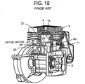
- Figs. 12 and 13 shows one structural embodiment of the stratified scavenging two-stroke cycle engine described in WO98/57053. A
piston 4 is provided so as to be slidably and in a sealing manner inserted within acylinder 3. Thepiston 4 is connected to acrank 5 within acrank chamber 11 via a connectingrod 6. A space portion in which a capacity above thepiston 4 within thecylinder 3 changes forms acylinder chamber 10. Twoscavenging flow passages cylinder chamber 10 with thecrank chamber 11 are provided on both side surfaces of thecylinder 3. The respectivescavenging flow passages scavenging ports cylinder chamber 10. Anexhaust port 22 is provided in an axial direction of thecylinder 3 and at a position in a top dead center side of thepiston 4 rather than thescavenging ports cylinder 3. Further, an air-fuelmixture suction port 23 and leadingair suction ports fuel mixture port 23 are provided on an inner peripheral surface of thecylinder 3. A throughhole 31 is provided in a lower portion of thepiston 4.Piston grooves air suction ports scavenging ports piston 4 are provided on right and left outer peripheral surfaces with respect to thethrough hole 31. - As shown in Fig. 14, in order to prevent the leading
air suction ports mixture suction port 23 from being communicated with each other in all the strokes of thepiston 4, an interval between two leadingair suction ports piston grooves mixture suction port 23. - In the stratified scavenging two-stroke cycle engine having the structure mentioned above, when the
piston 4 moves upward from a bottom dead center, a pressure of thecrank chamber 11 starts reducing and a pressure of thecylinder chamber 10 starts increasing, so that thescavenging port 21 and theexhaust port 22 are sequentially closed. Further, at this time, as shown in Fig. 14, the leadingair suction ports scavenging flow passages piston grooves scavenging ports mixture suction port 23 is opened so as to become in a state of being connected to thecrank chamber 11 via the throughhole 31. Accordingly, the air is sucked within thecrank chamber 11 from the leadingair suction ports scavenging flow passages scavenging flow passages - When the piston further moves upward and the
piston 4 reaches a point close to the top dead center, the air-fuel mixture within thecylinder chamber 10 is ignited and exploded, whereby thepiston 4 starts moving downward. Accordingly, the pressure of thecrank chamber 11 starts increasing, thepiston grooves air suction ports scavenging ports mixture suction port 23 becomes in a state of being closed by thepiston 4, so that the pressure within thecrank chamber 11 increases. - In the middle of the downward movement of the
piston 4, theexhaust port 22 and thescavenging ports cylinder chamber 10, and a combustion gas is at first discharged from theexhaust port 22. Next, the air stored within thescavenging flow passages cylinder chamber 10 from thescavenging ports crank chamber 11. Accordingly, the combustion gas left within thecylinder chamber 10 is expelled from theexhaust port 22 into an atmospheric air via a muffler (not shown). Next, the air-fuel mixture within thecrank chamber 11 is charged within thecylinder chamber 10 via thescavenging flow passages exhaust ports - Further, the
piston 4 starts moving upward from the bottom dead center, whereby the pressure within thecrank chamber 11 starts reducing, and thescavenging port 21 and theexhaust port 22 are sequentially closed, so that the cycle mentioned above is again repeated. - Further, conventionally, an air control valve for adjusting an air supply amount is provided in an upstream side of the leading air suction port. As one embodiment thereof, there has been known Japanese Utility Model Publication No. 55-4518.
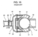
- Fig. 15 shows one structural embodiment of a stratified scavenging two-stroke cycle engine described in Japanese Utility Model Publication No. 55-4518, and Fig. 16 is a cross sectional view along a line 16-16 in Fig. 15. The same reference numerals are attached to the same elements as those in Fig. 12, a description thereof will be omitted, and a description will be given only of different parts. A
carburetor 50 having a suctionair throttle valve 51 is provided in the air-fuelmixture suction port 23 open to thecrank chamber 11. A two-forkedbranch pipe 61 attached to anair supply pipe 60 and branched into twoair supply passages cylinder 3. Theair supply passages branch pipe 61 are communicated with thescavenging ports cylinder chamber 10.Check valves air supply passages air control valve 63 having a butterflytype variable valve 64 is provided in theair supply pipe 60. Thevariable valve 64 is structured such as to be connected to the suctionair throttle valve 51 of thecarburetor 50 by arod 52 so as to interlock therewith. Anexhaust port 22 is provided on an opposing surface of theair supply pipe 60 of thecylinder 3. - In the structure mentioned above, when the
piston 4 starts moving upward from the bottom dead center, the air is supplied to thescavenging ports air supply pipe 60 via theair supply passages branch pipe 61. Then, an amount of air is adjusted by anair control valve 63. Theair control valve 63 is operated interlocking with the suctionair throttle valve 51 in thecarburetor 50, is set so that 0 or a fine amount is supplied at a time when the engine is under idling or under a low load operation, and an air at an amount corresponding to an operation condition is supplied at the other operation times. - However, in the structure disclosed in WO98/57053 mentioned above, the following problems are generated.
- In order to increase a suction efficiency of the air-fuel mixture, it is necessary to form the air-fuel
mixture suction port 23 to be equal to or more than a predetermined area. Further, in the same manner, in order to increase a suction efficiency and a scavenging efficiency of the leading air, it is necessary to form thescavenging ports piston grooves mixture suction port 23, thescavenging ports piston grooves - Further, in order to control so that the air supplied from the leading
air suction ports mixture suction port 23 do not mix, it is necessary to set the interval K between two leading air suction ports'24 and 24 to be larger than the width M of the air-fuelmixture suction port 23. Accordingly, a width N of the leadingair suction ports mixture suction port 23 and thescavenging ports air suction ports - Further, in the structure disclosed in Japanese Utility Model Publication No. 55-4518, the following problem is generated. Since the
air supply pipe 60 having theair control valve 63 is attached to thecylinder 3 via thebranch pipe 61, a number of the parts is increased, the structure is complex and a placing space is large. Accordingly, in the case that a product is constituted by using the engine, it becomes hard to assemble a whole of the structure in a compact manner, so that there are problems that a general purpose property is deteriorated and a cost is increased. - As a means for solving the problems mentioned above generated by WO98/57053, there can be considered a structure in which the air-fuel
mixture suction port 23 and two leadingair suction ports cylinder 3, and the interval between two leadingair suction ports mixture suction port 23. Fig. 18 is a side elevational schematic view of thecylinder 3 which describes an embodiment structured in the manner mentioned above. In Fig. 18, an interval R between two leadingair suction ports mixture suction port 23. Accordingly, it is possible to increase a width T of the leadingair suction ports - However, in this structure, in all of the strokes of the
piston 4, it is necessary to make thepiston groove 25 non-connection to the air-fuelmixture suction port 23. Accordingly, it is necessary to increase a length L2 of thepiston 4 at a degree of shifting the air-fuelmixture suction port 23 and two leadingair suction ports cylinder 3. Accordingly, since the engine itself becomes large, there are problems that the weight is increased, an occupied space is increased and a cost is increased. - The present invention is made by paying attention to the problems mentioned above, and an object of the present invention is to provide a stratified scavenging two-stroke cycle engine which can improve a leading air suction efficiency, can make a piston compact, has a simple structure, has a reduced number of parts, has a small placing space and has a low cost.
- In accordance with the present invention, there is provided a stratified scavenging two-stroke cycle engine comprising an exhaust port and a scavenging port which are connected to a cylinder chamber of an engine, a leading air suction port not connected to the cylinder chamber and a crank chamber in all of strokes of a piston, an air-fuel mixture suction port connected to the crank chamber, a scavenging flow passage connecting between the scavenging port and the crank chamber, a piston groove connecting between the leading air suction port and the scavenging port and not connecting between the air-fuel mixture suction port and the scavenging port at a time of a suction stroke, and provided in an outer peripheral portion of the piston; and the leading air suction port, the air-fuel mixture suction port and the scavenging port being opened and closed due to a vertical motion of the piston,
wherein the leading air suction port is positioned at an opposite side to the air-fuel mixture suction port with respect to an axis of the cylinder. - In accordance with the structure mentioned above, since the position of the leading air suction port is set to be opposite side to that of the air-fuel mixture suction port, it is possible to sufficiently secure an opening area of the leading air suction port even when the length of the piston is short. Accordingly, it is possible to obtain the stratified scavenging two-stroke cycle engine which has an improved leading air suction efficiency, is compact and light, has a small placing space and has a low cost.
- Further, the two-stroke cycle engine is structured such that the piston groove is not connected to the exhaust port at a top dead center, and an upper edge of the piston groove is positioned in a side of a cylinder head in a direction of the cylinder axis rather than a lower edge of the exhaust port within a range not overlapping in the direction of the cylinder axis with a width portion in a piston peripheral direction of the exhaust port.
- In accordance with the structure mentioned above, it is possible to increase a size in the cylinder axial direction of the piston groove. Accordingly, it is possible to increase a connecting time between the leading air suction port and the scavenging port at a time of the suction stroke so as to suck a lot of leading air. Therefore, since it is possible to increase a leading air suction efficiency even when reducing the length of the piston, it is possible to obtain the stratified scavenging two-stroke cycle engine which is compact and has an improved performance.
- Further, the structure may be made such that the two-stroke cycle engine further comprises an air control valve arranged close to the leading air suction port and adjusting a suction air amount.
- In accordance with the structure mentioned above, since the air control valve is provided close to the leading air suction port, a placing space is reduced, and a compact product structure can be obtained, so that a stratified scavenging two-stroke cycle engine excellent in a general purpose property can be obtained.
- Further, the two-stroke cycle may be structured such that a valve body of the air control valve is integrally formed with the cylinder.
- In accordance with the structure mentioned above, it is possible to reduce a number of the parts, make the structure simple, make the structure light and compact, and reduce a cost.
-
- Fig. 1 is a front elevational cross sectional view of a stratified scavenging two-stroke cycle engine having a leading air introduction apparatus in accordance with a first embodiment of the present invention;
- Fig. 2 is a side elevational cross sectional view of the stratified scavenging two-stroke cycle engine shown in Fig. 1;
- Fig. 3 is a cross sectional view along a line 3-3 in Fig. 1;
- Fig. 4 is a schematic view in a cross section 3-3 in Fig. 3;
- Fig. 5 is a schematic view showing an operation at a time of a piston bottom dead center in accordance with the first embodiment of the present invention;
- Fig. 6 is a schematic view showing an operation at a time of a piston middle point in accordance with the first embodiment of the present invention;
- Fig. 7 is a schematic view showing an operation at a time of a piston top dead center in accordance with the first embodiment of the present invention;
- Fig. 8 is a front elevational cross sectional view of a stratified scavenging two-stroke cycle engine having an air control valve in accordance with a second embodiment of the present invention;
- Fig. 9 is a cross sectional view along a line 9-9 in Fig. 8;
- Fig. 10 is a cross sectional view along a line 10-10 in Fig. 9;
- Fig. 11 is a cross sectional view of a main portion of a stratified scavenging two-stroke cycle engine having an air control valve in accordance with a third embodiment of the present invention;
- Fig. 12 is a broken perspective view of a main portion of a stratified scavenging two-stroke cycle engine in accordance with a conventional art;
- Fig. 13 is a plan cross sectional view of the stratified scavenging two-stroke cycle engine shown in Fig. 12, and corresponds to a cross sectional view along a line 13-13 in Fig. 14;
- Fig. 14 is a side elevational cross sectional view of a portion near a piston top dead center of the stratified scavenging two-stroke cycle engine shown in Fig. 12, and corresponds to a cross sectional view along a line 14-14 in Fig. 13;
- Fig. 15 is a front elevational cross sectional view of a stratified scavenging two-stroke cycle engine provided with an air control valve in accordance with the conventional art;
- Fig. 16 is a cross sectional view along a line 16-16 in Fig. 15;
- Fig. 17 is a plan cross sectional view of a cylinder portion at a time of a piston top dead center of the stratified scavenging two-stroke cycle engine shown in Fig. 12; and
-
- Fig. 18 is a side elevational schematic view of a cylinder describing a structural embodiment in which an air-fuel mixture suction port and two leading air suction ports are provided so as to be shifted to each other in a direction of a cylinder axis at a predetermined distance.
- A description will be in detail given below of a preferred embodiment of a stratified scavenging two-stroke cycle engine in accordance with the present invention with reference to Figs. 1 to 11.
- Fig. 1 is a front elevational cross sectional view in a piston top dead center of a stratified scavenging two-
stroke cycle engine 1 in accordance with a first embodiment, and Fig. 2 is a side elevational cross sectional view. In Figs. 1 and 2, apiston 4 is closely and slidably inserted to acylinder 3 attached to an upper side of a crankcase 2. Acrank 5 and thepiston 4 which are rotatably attached to the crankcase 2 are connected by a connectingrod 6. A space portion having a variable capacity and disposed in an upper side of thepiston 4 within thecylinder 3 forms acylinder chamber 10. Further, a space portion disposed in a lower side of thepiston 4 and surrounded by thecylinder 3 and the crankcase 2 forms a crankchamber 11. Acylinder head 7 is provided in an upper portion of thecylinder 3. Anexhaust port 22 and a leadingair suction port 24 are provided in one side of an inner peripheral surface of thecylinder 3, and an air-fuelmixture suction port 23 is provided in another side. Further, scavengingflow passages cylinder chamber 10 to the crankchamber 11 are respectively provided on both side surfaces of thecylinder 3. The scavengingflow passages cylinder chamber 10 are open to the inner peripheral surface of thecylinder 3 so as to form scavengingports flow passages ports cylinder 3, however, the structure may be made such that onescavenging flow passage 20 and one scavengingport 21 are respectively provided in one side of thecylinder 3.Piston grooves air suction port 24 to the scavengingport 21 at a time of the suction stroke are respectively provided on outer peripheral surface portions in both sides of thepiston 4. - As shown in Fig. 3, the leading
air suction port 24 and theexhaust port 22 are provided in an opposite side to the air-fuelmixture suction port 23 with respect to a center axis (an axis) P of thecylinder 3. Two scavengingports mixture suction port 23 and the leadingair suction port 24. Twopistons piston 4 are provided at positions connecting the scavengingport 21 to the leadingair suction port 24. In this case, the position of the scavengingport 21 is not always limited to the position at 90 degrees, and can be suitably selected in correspondence to a positional relation between the leadingair suction port 24 and theexhaust port 22, and may be asymmetrical. Further, the number of the scavengingports 21 is not limited to two. - Fig. 4 corresponds to a development in a cross section along a line 4-4 in Fig. 3, and shows a mutual positional relation among the scavenging
port 21, theexhaust port 22, the air-fuelmixture suction port 23, the leadingair suction port 24 and thepiston grooves piston grooves exhaust port 22 and the air-fuel mixture port 23 at the piston top dead center position, and connects the scavengingport 21 to the leadingair suction port 24. Then, a piston grooveupper edge 25a is positioned in a side of thecylinder head 7 at a distance G in the axial direction of thepiston 4 rather than an exhaust portlower edge 22a. Further, a leading air suction portupper edge 24a is positioned in a side of thecrank chamber 11 at a distance H in the axial direction of thepiston 4 rather than the exhaust portlower edge 22a. Accordingly, it is possible to reduce an interval E between two leadingair suction ports exhaust port 22, and it is possible to increase a width F of the leadingair suction port 24 so as to increase a leading air suction area. Further, since the piston grooveupper edge 25a is positioned in the side of thecylinder head 7 at the distance G rather than the exhaust portlower edge 22a, it is possible to increase a size J in the cylinder axial direction of thepiston groove 25 even when reducing an axial length L of thecylinder 3. In this case, thepiston groove 25 is provided at a position not being connected to the air-fuelmixture suction port 23 between the piston top dead center position and the piston bottom dead center position shown by a two-dot chain line. - Next, a description will be given of an operation of the structure mentioned above. Fig. 5 is a schematic view showing a positional relation of the respective ports at the piston bottom dead center position corresponding to a final stroke of an explosion and an exhaust at which the
piston 4 moves downward. The scavengingport 21 and theexhaust port 22 are connected to thecylinder chamber 10. The pistonupper edge 4a is positioned close to the exhaust portlower edge 22a. The leadingair suction port 24 is closed by thepiston 4, and the leadingair suction port 24 and the scavengingport 21 are not connected. The scavengingport 21 is connected to the crankchamber 11 via the scavengingflow passage 20, and the air-fuelmixture suction port 23 is closed by thepiston 4. That is, the exhaust gas is discharged from theexhaust port 22 due to the leading air pressed out from the scavengingport 21. The air-fuel mixture in thecrank chamber 11 is supplied to thecylinder chamber 10 from the scavengingport 21 through the scavengingflow passage 20. - Fig. 6 shows a positional relation of the respective ports at the middle stroke of the compression and the suction at which the
piston 4 moves upward, and shows a state that thepiston 25 starts connecting to the leadingair suction port 24. That is, theexhaust port 22 and the scavengingport 21 are closed by thepiston 4. The piston grooveupper edge 25a is at the position of the scavenging portlower edge 21a, and the leadingair suction port 24 and the scavengingport 21 are in a state of starting connecting via thepiston groove 25. Further, the pistonlower edge 4b is at the position of the air-fuel mixture suction portlower edge 23a, and in a state of starting sucking the air-fuel mixture. In this state, the air-fuel mixture in thecylinder chamber 10 is compressed, and an internal pressure of thecrank chamber 11 is reduced. In this case, with respect to the timings of opening and closing the leadingair suction port 24 and the air-fuelmixture suction port 23, the timings are set to be simultaneous, however, it is not necessary to always set to be simultaneous. - When the
piston 4 moves upward from the state shown in Fig. 6, the leadingair suction port 24 is connected to the scavengingport 21 via thepiston groove 25, and the leading air flows into the scavengingflow passage 20. At the same time, the air-fuelmixture suction port 23 is opened so as to be connected to the crankchamber 11, and the air-fuel mixture is sucked into thecrank chamber 11. - Next, when the
piston 4 reaches the top dead center position as shown in Fig. 7, theexhaust port 22 is closed by thepiston 4, the leadingair suction port 24 and the scavengingport 21 are connected in a full open state via thepiston groove 25, and the air-fuelmixture suction port 23 is connected in a full open state to the crankchamber 11. - As mentioned above, in the stratified scavenging two-
stroke cycle engine 1 in accordance with the first embodiment, since the positions of the leadingair suction ports mixture suction port 23, it is possible to increase the opening area of the leadingair suction ports piston 4 is short. Further, the piston grooveupper edge 25a within the range not overlapping in the cylinder axial direction with the width portion in the piston peripheral direction of theexhaust port 22 is positioned in the side of thecylinder head 7 in the cylinder axial direction rather than the exhaust portlower edge 22a. Accordingly, it is possible to increase the size J in the cylinder axial direction of thepiston groove 25. Therefore, it is possible to increase the cross sectional area of thepiston groove 25, that is, the leading air passing area, and it is possible to increase the connection time between the leadingair suction port 24 and the scavengingport 21 at a time when thepiston 4 vertically moves so as to suck a lot of leading air, so that it is possible to improve a suction efficiency of the leading air. Further, since the length of thepiston 4 can be made the same as the conventional one even when increasing the area of the leadingair suction port 24, it is possible to make the structure compact and light, and it is possible to obtain the stratified scavenging two-stroke cycle engine 1 having a reduced cost. - Fig. 8 is a front elevational cross sectional view of a stratified scavenging two-
stroke cycle engine 1 provided with an air control valve in accordance with a second embodiment, and Fig. 9 is a cross sectional view along a line 9-9 in Fig. 8. The same reference numerals are attached to the same elements as those shown in Fig. 1, a description will be omitted and a description will be given of only different parts. In Figs. 8 and 9, acarburetor 50 having anair throttle valve 51 is arranged in an upstream side of an air-fuelmixture suction port 23. A rotary valve typeair control valve 30 is attached to a portion in an inlet port of a leadingair suction passage 26 communicating with a leadingair suction port 24 of acylinder 3 and below anexhaust pipe 27 connecting to anexhaust port 22. A steppedcylindrical hole 32 is provided in avalve body 31 of theair control valve 30, and arotary valve 40 is rotatably inserted to the steppedcylindrical hole 32. Anair intake port 34 communicating with the steppedcylindrical hole 32 is provided at an end portion in a side of a steppedportion 33 of the steppedcylindrical hole 32, and is connected to an air cleaner (not shown) via a suction pipe (not shown). Anair discharge port 36 connecting the steppedcylinder hole 32 to the leadingair suction passage 26 is provided on a mountingsurface 35 of thevalve body 31 to thecylinder 3. Aflange 37 is provided in thevalve body 31, and is fastened to thecylinder 3 by abolt 38. Anair communication hole 41 communicating with theair intake port 34 is provided in therotary valve 40. Further, acommunication hole 42 rotating so as to open and close the communication passage between theair communication hole 41 and the leadingair suction passage 26 is provided on a wall surface of therotary valve 40. - Fig. 10 corresponding to a cross sectional view along a line 10-10 in Fig. 9 shows a state that the valve is opened. The
air discharge port 36 provided in thevalve body 31 is formed in a rectangular shape, on the contrary, thecommunication hole 42 provided in therotary valve 40 is formed in a meniscus shape. Accordingly, in the case of rotating therotary valve 40 from a closed position to an open position, the passage gradually starts opening from a top portion V of a circular arc, and can gradually increase the passage area. A lever 43 (refer to Fig. 9) provided in one end portion of therotary valve 40 is connected to the air throttle valve 51 (refer to Fig. 8) of thecarburetor 50 by a link apparatus (not shown) so as to interlock therewith. It is executed by thelever 43 to make the opening area zero or small at a time when the engine is under an idling or under a low load operation, or it is executed to increase the opening area in correspondence to the load at a time when the engine is under a high load, whereby a necessary air can be sucked. - As shown in Fig. 9, when the
rotary valve 40 is rotated, and thecommunication hole 42 and theair discharge port 36 are communicated, the air passes through theair communication hole 41 from theair intake port 34 as shown by an arrow and is supplied to the leadingair suction port 24 from the leadingair suction passage 26. - As described above, in accordance with the second embodiment, the rotary valve type
air control valve 30 is arranged close to the leadingair suction port 24. Accordingly, it is possible to supply a predetermined amount of leading air in correspondence to the engine load, the structure can be made compact, simple and light, the structure can be made compact in the case of constituting the product, and it is possible to obtain a low cost stratified scavenging two-stroke cycle engine 1. - Fig. 11 is a cross sectional view of a main portion of a stratified scavenging two-
stroke cycle engine 1 provided with anair control valve 30a in accordance with a third embodiment. Avalve body 31a integrally formed with acylinder 3 is provided in a terminal portion of a leadingair suction passage 26 in thecylinder 3. Arotary valve 40 is rotatably inserted to a steppedcylindrical hole 32 pierced in thevalve body 31a. Since structures and operations of the other members are the same as that of theair control valve 30 in accordance with the second embodiment, a description thereof will be omitted. - In the third embodiment, since the
valve body 31a is integrally structured with thecylinder 3, the number of the parts is reduced and a simple structure can be obtained, so that the structure can be made more compact and the cost can be reduced. - The present invention is useful for the stratified scavenging two-stroke cycle engine which can improve a suction efficiency of the leading air, make the piston compact, and has a simple structure and a low cost.
Claims (4)
- A stratified scavenging two-stroke cycle engine comprising:an exhaust port (22) and a scavenging port (21) which are connected to a cylinder chamber (10) of an engine;a leading air suction port (24) not connected to said cylinder chamber (10) and a crank chamber (11) in all of strokes of a piston (4);an air-fuel mixture suction port (23) connected to said crank chamber (11);a scavenging flow passage (20) connecting between said scavenging port (21) and said crank chamber (11);a piston groove (25) connecting between said leading air suction port (24) and said scavenging port (21) and not connecting between said air-fuel mixture suction port (23) and said scavenging port (21) at a time of a suction stroke, and provided in an outer peripheral portion of said piston (4); andsaid leading air suction port (24), said air-fuel mixture suction port (23) and said scavenging port (21) being opened and closed due to a vertical motion of said piston (4);
wherein said leading air suction port (24) is positioned at an opposite side to said air-fuel mixture suction port (23) with respect to an axis of said cylinder (3). - A stratified scavenging two-stroke cycle engine as claimed in claim 1, wherein said piston groove (25) is not connected to said exhaust port (22) at a top dead center, and an upper edge (25a) of the piston groove is positioned in a side of a cylinder head (7) in a direction of the cylinder (3) axis rather than a lower edge (22a) of the exhaust port within a range not overlapping in the direction of the cylinder axis with a width portion in a piston peripheral direction of said exhaust port.
- A stratified scavenging two-stroke cycle engine as claimed in claim 1 or 2, further comprising an air control valve (30) arranged close to said leading air suction port (24) and adjusting a suction air amount.
- A stratified scavenging two-stroke cycle engine as claimed in claim 3, wherein a valve body (31a) of said air control valve (30) is integrally formed with said cylinder (3).
Applications Claiming Priority (3)
| Application Number | Priority Date | Filing Date | Title |
|---|---|---|---|
| JP11711899 | 1999-04-23 | ||
| JP11711899 | 1999-04-23 | ||
| PCT/JP2000/001943 WO2000065209A1 (en) | 1999-04-23 | 2000-03-29 | Stratified scavenging two-stroke cycle engine |
Publications (3)
| Publication Number | Publication Date |
|---|---|
| EP1176296A1 true EP1176296A1 (en) | 2002-01-30 |
| EP1176296A4 EP1176296A4 (en) | 2008-06-25 |
| EP1176296B1 EP1176296B1 (en) | 2009-06-17 |
Family
ID=14703882
Family Applications (1)
| Application Number | Title | Priority Date | Filing Date |
|---|---|---|---|
| EP00912907A Expired - Lifetime EP1176296B1 (en) | 1999-04-23 | 2000-03-29 | Stratified scavenging two-stroke cycle engine |
Country Status (6)
| Country | Link |
|---|---|
| US (1) | US6497204B1 (en) |
| EP (1) | EP1176296B1 (en) |
| JP (1) | JP3592237B2 (en) |
| AU (1) | AU3453500A (en) |
| DE (1) | DE60042402D1 (en) |
| WO (1) | WO2000065209A1 (en) |
Cited By (3)
| Publication number | Priority date | Publication date | Assignee | Title |
|---|---|---|---|---|
| FR2840019A1 (en) * | 2002-05-24 | 2003-11-28 | Stihl Ag & Co Kg Andreas | Two-stroke motor for a hand-held tool such as a power saw or brush cutter comprises transfer ports connected to an air duct at different times during operation of the motor |
| DE10312092B4 (en) * | 2002-05-24 | 2013-10-10 | Andreas Stihl Ag & Co. Kg | Two-stroke engine |
| DE10301732B4 (en) * | 2003-01-18 | 2020-01-30 | Andreas Stihl Ag & Co. Kg | Two-stroke engine and method for its operation |
Families Citing this family (22)
| Publication number | Priority date | Publication date | Assignee | Title |
|---|---|---|---|---|
| SE513446C2 (en) | 1999-01-19 | 2000-09-11 | Electrolux Ab | Crankcase coil internal combustion engine of two stroke type |
| US7082910B2 (en) * | 1999-01-19 | 2006-08-01 | Aktiebolaget Electrolux | Two-stroke internal combustion engine |
| SE0000095L (en) | 2000-01-14 | 2001-07-15 | Electrolux Ab | Damper for regulating auxiliary air for two-stroke internal combustion engines |
| JP2003519749A (en) | 2000-01-14 | 2003-06-24 | アクティエボラゲット エレクトロラックス | Two-stroke internal combustion engine |
| RU2230913C2 (en) | 2000-01-14 | 2004-06-20 | Актиеболагет Электролюкс | Two-stroke internal combustion engine |
| CN100386511C (en) | 2000-04-27 | 2008-05-07 | 哈斯科瓦那股份公司 | Two-stroke IC engine |
| DE10223070B4 (en) * | 2002-05-24 | 2015-10-08 | Andreas Stihl Ag & Co. | Two-stroke engine |
| DE10223069A1 (en) * | 2002-05-24 | 2003-12-11 | Stihl Maschf Andreas | Two-stroke engine |
| DE10229365B4 (en) * | 2002-06-29 | 2013-10-31 | Andreas Stihl Ag & Co. | Two-stroke engine and method of operation |
| WO2004038195A1 (en) * | 2002-10-11 | 2004-05-06 | Kawasaki Jukogyo Kabushiki Kaisha | Air scavenging-type two-cycle engine |
| US7021252B2 (en) * | 2004-03-04 | 2006-04-04 | Electrolux Home Products, Inc. | Sas piston channel for optimum air scavenging |
| US7146941B2 (en) * | 2004-12-22 | 2006-12-12 | Komatsu Zenoah Co. | Rotary valve |
| DE102005002013B4 (en) * | 2005-01-15 | 2016-05-12 | Andreas Stihl Ag & Co. Kg | Two-stroke engine |
| US7331315B2 (en) | 2005-02-23 | 2008-02-19 | Eastway Fair Company Limited | Two-stroke engine with fuel injection |
| DE102006001567B4 (en) * | 2006-01-12 | 2007-11-29 | Andreas Stihl Ag & Co. Kg | implement |
| DE102007026121B4 (en) | 2007-06-05 | 2019-10-17 | Andreas Stihl Ag & Co. Kg | Internal combustion engine and method for its operation |
| US8534268B2 (en) * | 2009-09-14 | 2013-09-17 | Nagesh Mavinahally | Two-stroke engine |
| JP5370669B2 (en) * | 2009-10-07 | 2013-12-18 | 株式会社やまびこ | 2-cycle engine |
| DE102010045016B4 (en) * | 2010-09-10 | 2020-12-31 | Andreas Stihl Ag & Co. Kg | Hand-held tool |
| JP5780888B2 (en) * | 2010-12-13 | 2015-09-16 | 株式会社やまびこ | 2-cycle engine |
| DE112012001120A5 (en) * | 2011-03-09 | 2014-01-02 | Makita Corporation | Two-stroke engine with a silencer |
| US9856819B2 (en) | 2014-02-02 | 2018-01-02 | Nagesh Siddabasappa Mavinahally | Piston and cylinder for two-stroke engine |
Citations (6)
| Publication number | Priority date | Publication date | Assignee | Title |
|---|---|---|---|---|
| US2477712A (en) * | 1947-01-24 | 1949-08-02 | Nordberg Manufacturing Co | Port-scavenged two-cycle internalcombustion engine |
| CH313444A (en) * | 1952-03-28 | 1956-04-15 | Isler Fritz | Two-stroke internal combustion engine |
| US3687118A (en) * | 1969-07-14 | 1972-08-29 | Yamaha Hatsudaki Kk | Crank chamber compression-type two-cycle engine |
| DE2943496A1 (en) * | 1978-12-13 | 1980-06-26 | Zschopau Motorrad Veb | Cylinder in two stroke IC engine - has baffle plate below piston forming chambers connected to inlet channels and overflow ducts |
| JPS59170423A (en) * | 1983-03-18 | 1984-09-26 | Nippon Clean Engine Res | Laminar scavenging 2-cycle engine |
| US4848279A (en) * | 1988-02-03 | 1989-07-18 | Industrial Technology Research Institute | Air-injection device for two-stroke engines |
Family Cites Families (9)
| Publication number | Priority date | Publication date | Assignee | Title |
|---|---|---|---|---|
| JPS584167B2 (en) | 1974-08-06 | 1983-01-25 | ヤマハハツドウキ カブシキガイシヤ | Crank tension 2 cycle engine |
| DE2711641A1 (en) | 1977-03-17 | 1978-09-21 | Walter Franke | METHOD OF OPERATING A TWO-STROKE ENGINE AND TWO-STROKE ENGINE FOR CARRYING OUT THIS PROCEDURE |
| JPS554518U (en) | 1978-06-23 | 1980-01-12 | ||
| JPS554518A (en) | 1978-06-26 | 1980-01-14 | Hitachi Ltd | Crank angle detector of engines |
| DE3735710A1 (en) | 1987-10-22 | 1989-05-03 | Stihl Maschf Andreas | TWO-STROKE MOTOR FOR FAST-RUNNING WORK TOOLS |
| US5379732A (en) | 1993-11-12 | 1995-01-10 | Mavinahally; Nagesh S. | Continuously variable volume scavenging passage for two-stroke engines |
| JPH07269356A (en) | 1994-03-29 | 1995-10-17 | Ishikawajima Shibaura Mach Co Ltd | Two-cycle engine |
| JP3934198B2 (en) | 1997-03-10 | 2007-06-20 | 日本ウォルブロー株式会社 | Two-stroke internal combustion engine carburetor |
| WO1998057053A1 (en) | 1997-06-11 | 1998-12-17 | Komatsu Zenoah Co. | Stratified scavenging two-cycle engine |
-
2000
- 2000-03-29 DE DE60042402T patent/DE60042402D1/en not_active Expired - Lifetime
- 2000-03-29 AU AU34535/00A patent/AU3453500A/en not_active Abandoned
- 2000-03-29 US US09/959,047 patent/US6497204B1/en not_active Expired - Lifetime
- 2000-03-29 JP JP2000613931A patent/JP3592237B2/en not_active Expired - Lifetime
- 2000-03-29 WO PCT/JP2000/001943 patent/WO2000065209A1/en active Application Filing
- 2000-03-29 EP EP00912907A patent/EP1176296B1/en not_active Expired - Lifetime
Patent Citations (6)
| Publication number | Priority date | Publication date | Assignee | Title |
|---|---|---|---|---|
| US2477712A (en) * | 1947-01-24 | 1949-08-02 | Nordberg Manufacturing Co | Port-scavenged two-cycle internalcombustion engine |
| CH313444A (en) * | 1952-03-28 | 1956-04-15 | Isler Fritz | Two-stroke internal combustion engine |
| US3687118A (en) * | 1969-07-14 | 1972-08-29 | Yamaha Hatsudaki Kk | Crank chamber compression-type two-cycle engine |
| DE2943496A1 (en) * | 1978-12-13 | 1980-06-26 | Zschopau Motorrad Veb | Cylinder in two stroke IC engine - has baffle plate below piston forming chambers connected to inlet channels and overflow ducts |
| JPS59170423A (en) * | 1983-03-18 | 1984-09-26 | Nippon Clean Engine Res | Laminar scavenging 2-cycle engine |
| US4848279A (en) * | 1988-02-03 | 1989-07-18 | Industrial Technology Research Institute | Air-injection device for two-stroke engines |
Non-Patent Citations (1)
| Title |
|---|
| See also references of WO0065209A1 * |
Cited By (5)
| Publication number | Priority date | Publication date | Assignee | Title |
|---|---|---|---|---|
| FR2840019A1 (en) * | 2002-05-24 | 2003-11-28 | Stihl Ag & Co Kg Andreas | Two-stroke motor for a hand-held tool such as a power saw or brush cutter comprises transfer ports connected to an air duct at different times during operation of the motor |
| WO2003100229A1 (en) * | 2002-05-24 | 2003-12-04 | Andreas Stihl Ag & Co. Kg | Two-stroke motor |
| US6945203B2 (en) | 2002-05-24 | 2005-09-20 | Andreas Stihl Ag & Co Kg | Two-cycle engine |
| DE10312092B4 (en) * | 2002-05-24 | 2013-10-10 | Andreas Stihl Ag & Co. Kg | Two-stroke engine |
| DE10301732B4 (en) * | 2003-01-18 | 2020-01-30 | Andreas Stihl Ag & Co. Kg | Two-stroke engine and method for its operation |
Also Published As
| Publication number | Publication date |
|---|---|
| WO2000065209A1 (en) | 2000-11-02 |
| EP1176296A4 (en) | 2008-06-25 |
| US6497204B1 (en) | 2002-12-24 |
| AU3453500A (en) | 2000-11-10 |
| DE60042402D1 (en) | 2009-07-30 |
| JP3592237B2 (en) | 2004-11-24 |
| EP1176296B1 (en) | 2009-06-17 |
Similar Documents
| Publication | Publication Date | Title |
|---|---|---|
| EP1176296B1 (en) | Stratified scavenging two-stroke cycle engine | |
| EP2039908B1 (en) | Stratified scavenging two-cycle engine | |
| US7363888B2 (en) | Two-stroke engine | |
| US5628295A (en) | Two-stroke internal combustion engine | |
| CA1248027A (en) | Air-scavenged two-cycle internal combustion engine | |
| CA2464227A1 (en) | Double action piston assembly | |
| JPH02204625A (en) | Two-cycle engine | |
| US20030079715A1 (en) | Integral air compressor for boost air in barrel engine | |
| US6450135B1 (en) | Two-stroke internal combustion engine | |
| US7128031B2 (en) | Lead air control apparatus of stratified scavenging two-cycle engine | |
| CN113107661A (en) | Layered scavenging two-stroke engine | |
| US6591793B2 (en) | Two-cycle engine | |
| JPS60153427A (en) | Supercharged multi-cylinder internal-combustion engine | |
| JPS6088810A (en) | Internal-combustion engine | |
| US20030226524A1 (en) | Bazmi's six stroke engine | |
| US6789513B2 (en) | Bazmi's six-stroke engine with intake-exhaust valves | |
| JP2001329844A (en) | Two-cycle engine | |
| US20100050983A1 (en) | Four-stroke internal combustion engine with novel intake and exhaust strokes | |
| AU721527B2 (en) | Exhaust controller for spark ignition type two stroke internal combustion engine | |
| JPH0144740Y2 (en) | ||
| JP2816980B2 (en) | Supercharged reciprocating engine | |
| JPH0212268Y2 (en) | ||
| JPH0115866Y2 (en) | ||
| EP2681426B1 (en) | Two-stroke internal combustion engine | |
| JP4288032B2 (en) | 2-cycle engine |
Legal Events
| Date | Code | Title | Description |
|---|---|---|---|
| PUAI | Public reference made under article 153(3) epc to a published international application that has entered the european phase |
Free format text: ORIGINAL CODE: 0009012 |
|
| 17P | Request for examination filed |
Effective date: 20011120 |
|
| AK | Designated contracting states |
Kind code of ref document: A1 Designated state(s): DE FR GB IT SE |
|
| RAP1 | Party data changed (applicant data changed or rights of an application transferred) |
Owner name: ZENOAH CO., LTD. |
|
| RAP1 | Party data changed (applicant data changed or rights of an application transferred) |
Owner name: HUSQVARNA ZENOAH CO., LTD. |
|
| A4 | Supplementary search report drawn up and despatched |
Effective date: 20080526 |
|
| GRAP | Despatch of communication of intention to grant a patent |
Free format text: ORIGINAL CODE: EPIDOSNIGR1 |
|
| GRAC | Information related to communication of intention to grant a patent modified |
Free format text: ORIGINAL CODE: EPIDOSCIGR1 |
|
| GRAS | Grant fee paid |
Free format text: ORIGINAL CODE: EPIDOSNIGR3 |
|
| GRAA | (expected) grant |
Free format text: ORIGINAL CODE: 0009210 |
|
| AK | Designated contracting states |
Kind code of ref document: B1 Designated state(s): DE FR GB IT SE |
|
| REG | Reference to a national code |
Ref country code: GB Ref legal event code: FG4D |
|
| REF | Corresponds to: |
Ref document number: 60042402 Country of ref document: DE Date of ref document: 20090730 Kind code of ref document: P |
|
| PG25 | Lapsed in a contracting state [announced via postgrant information from national office to epo] |
Ref country code: SE Free format text: LAPSE BECAUSE OF FAILURE TO SUBMIT A TRANSLATION OF THE DESCRIPTION OR TO PAY THE FEE WITHIN THE PRESCRIBED TIME-LIMIT Effective date: 20090917 |
|
| PLBE | No opposition filed within time limit |
Free format text: ORIGINAL CODE: 0009261 |
|
| STAA | Information on the status of an ep patent application or granted ep patent |
Free format text: STATUS: NO OPPOSITION FILED WITHIN TIME LIMIT |
|
| 26N | No opposition filed |
Effective date: 20100318 |
|
| PGFP | Annual fee paid to national office [announced via postgrant information from national office to epo] |
Ref country code: IT Payment date: 20100323 Year of fee payment: 11 Ref country code: FR Payment date: 20100324 Year of fee payment: 11 |
|
| PGFP | Annual fee paid to national office [announced via postgrant information from national office to epo] |
Ref country code: GB Payment date: 20100322 Year of fee payment: 11 |
|
| GBPC | Gb: european patent ceased through non-payment of renewal fee |
Effective date: 20110329 |
|
| REG | Reference to a national code |
Ref country code: FR Ref legal event code: ST Effective date: 20111130 |
|
| PG25 | Lapsed in a contracting state [announced via postgrant information from national office to epo] |
Ref country code: FR Free format text: LAPSE BECAUSE OF NON-PAYMENT OF DUE FEES Effective date: 20110331 |
|
| PG25 | Lapsed in a contracting state [announced via postgrant information from national office to epo] |
Ref country code: IT Free format text: LAPSE BECAUSE OF NON-PAYMENT OF DUE FEES Effective date: 20110329 Ref country code: GB Free format text: LAPSE BECAUSE OF NON-PAYMENT OF DUE FEES Effective date: 20110329 |
|
| PGFP | Annual fee paid to national office [announced via postgrant information from national office to epo] |
Ref country code: DE Payment date: 20160205 Year of fee payment: 17 |
|
| REG | Reference to a national code |
Ref country code: DE Ref legal event code: R119 Ref document number: 60042402 Country of ref document: DE |
|
| PG25 | Lapsed in a contracting state [announced via postgrant information from national office to epo] |
Ref country code: DE Free format text: LAPSE BECAUSE OF NON-PAYMENT OF DUE FEES Effective date: 20171003 |