EP1176086A1 - Châssis à soudures réduites, longeron pour un tel châssis et procédé de fabrication d'un tel longeron - Google Patents
Châssis à soudures réduites, longeron pour un tel châssis et procédé de fabrication d'un tel longeron Download PDFInfo
- Publication number
- EP1176086A1 EP1176086A1 EP01401998A EP01401998A EP1176086A1 EP 1176086 A1 EP1176086 A1 EP 1176086A1 EP 01401998 A EP01401998 A EP 01401998A EP 01401998 A EP01401998 A EP 01401998A EP 1176086 A1 EP1176086 A1 EP 1176086A1
- Authority
- EP
- European Patent Office
- Prior art keywords
- core
- height
- spar
- reduced
- chassis
- Prior art date
- Legal status (The legal status is an assumption and is not a legal conclusion. Google has not performed a legal analysis and makes no representation as to the accuracy of the status listed.)
- Granted
Links
- 238000000034 method Methods 0.000 title claims abstract description 9
- 230000008569 process Effects 0.000 title abstract description 3
- 238000003466 welding Methods 0.000 claims abstract description 24
- 238000004519 manufacturing process Methods 0.000 claims abstract description 5
- 239000000725 suspension Substances 0.000 claims description 18
- 238000005452 bending Methods 0.000 claims description 5
- 238000005520 cutting process Methods 0.000 claims description 2
- 229910045601 alloy Inorganic materials 0.000 description 7
- 239000000956 alloy Substances 0.000 description 7
- 240000008042 Zea mays Species 0.000 description 3
- 230000008901 benefit Effects 0.000 description 3
- 230000000295 complement effect Effects 0.000 description 3
- 238000010276 construction Methods 0.000 description 3
- 230000009467 reduction Effects 0.000 description 3
- 239000010953 base metal Substances 0.000 description 2
- 230000007423 decrease Effects 0.000 description 2
- 238000002955 isolation Methods 0.000 description 2
- 239000000463 material Substances 0.000 description 2
- 229910000838 Al alloy Inorganic materials 0.000 description 1
- 241001669679 Eleotris Species 0.000 description 1
- 229910017708 MgZn2 Inorganic materials 0.000 description 1
- 241000897276 Termes Species 0.000 description 1
- 244000245420 ail Species 0.000 description 1
- 230000004075 alteration Effects 0.000 description 1
- 229910052782 aluminium Inorganic materials 0.000 description 1
- XAGFODPZIPBFFR-UHFFFAOYSA-N aluminium Chemical compound [Al] XAGFODPZIPBFFR-UHFFFAOYSA-N 0.000 description 1
- 230000000712 assembly Effects 0.000 description 1
- 238000000429 assembly Methods 0.000 description 1
- 239000011324 bead Substances 0.000 description 1
- 230000008859 change Effects 0.000 description 1
- 230000008878 coupling Effects 0.000 description 1
- 238000010168 coupling process Methods 0.000 description 1
- 238000005859 coupling reaction Methods 0.000 description 1
- 238000001125 extrusion Methods 0.000 description 1
- 238000009472 formulation Methods 0.000 description 1
- 238000005304 joining Methods 0.000 description 1
- 229910052751 metal Inorganic materials 0.000 description 1
- 239000002184 metal Substances 0.000 description 1
- 239000000203 mixture Substances 0.000 description 1
- 230000004048 modification Effects 0.000 description 1
- 238000012986 modification Methods 0.000 description 1
- 230000035515 penetration Effects 0.000 description 1
- 238000001556 precipitation Methods 0.000 description 1
- 230000003313 weakening effect Effects 0.000 description 1
- 238000005493 welding type Methods 0.000 description 1
Images




Classifications
-
- B—PERFORMING OPERATIONS; TRANSPORTING
- B62—LAND VEHICLES FOR TRAVELLING OTHERWISE THAN ON RAILS
- B62D—MOTOR VEHICLES; TRAILERS
- B62D53/00—Tractor-trailer combinations; Road trains
- B62D53/04—Tractor-trailer combinations; Road trains comprising a vehicle carrying an essential part of the other vehicle's load by having supporting means for the front or rear part of the other vehicle
- B62D53/06—Semi-trailers
-
- B—PERFORMING OPERATIONS; TRANSPORTING
- B62—LAND VEHICLES FOR TRAVELLING OTHERWISE THAN ON RAILS
- B62D—MOTOR VEHICLES; TRAILERS
- B62D21/00—Understructures, i.e. chassis frame on which a vehicle body may be mounted
-
- B—PERFORMING OPERATIONS; TRANSPORTING
- B62—LAND VEHICLES FOR TRAVELLING OTHERWISE THAN ON RAILS
- B62D—MOTOR VEHICLES; TRAILERS
- B62D21/00—Understructures, i.e. chassis frame on which a vehicle body may be mounted
- B62D21/18—Understructures, i.e. chassis frame on which a vehicle body may be mounted characterised by the vehicle type and not provided for in groups B62D21/02 - B62D21/17
- B62D21/20—Understructures, i.e. chassis frame on which a vehicle body may be mounted characterised by the vehicle type and not provided for in groups B62D21/02 - B62D21/17 trailer type, i.e. a frame specifically constructed for use in a non-powered vehicle
-
- B—PERFORMING OPERATIONS; TRANSPORTING
- B60—VEHICLES IN GENERAL
- B60G—VEHICLE SUSPENSION ARRANGEMENTS
- B60G2206/00—Indexing codes related to the manufacturing of suspensions: constructional features, the materials used, procedures or tools
- B60G2206/01—Constructional features of suspension elements, e.g. arms, dampers, springs
- B60G2206/60—Subframe construction
- B60G2206/601—Hanger bracket
Definitions
- the invention relates to a chassis with reduced welds, a spar for such a chassis and a method of manufacturing such a spar.
- the invention relates more particularly to a welded chassis reduced for a commercial vehicle.
- the chassis of commercial vehicles are mostly made of two longitudinal beams, called spars, braced by means of sleepers. On these beams, there is a loading floor, also called a tray, a tank, a bucket, a box or a container.
- a loading floor also called a tray, a tank, a bucket, a box or a container.
- rails are generally used having a constant section, for example in I.
- the chassis beams of semi-trailers and of trailers often do not have a constant cross section over their entire length.
- Various shapes of spar are thus produced.
- the different forms of I-beam are obtained by cutting a core member from a sheet according to the desired shape and by welding on the opposite longitudinal edges of this sheet metal strips intended to form the wings of the side members.
- the wings of the side members are formed by T-profiles, partially curved, formed by bands provided with ribs central high enough to be able to distance the welds from the wings, that is to say places of the highest demand.
- Spars of forms varied are obtained correspondingly. So, for example, a J-spar, i.e.
- a spar with two wings arranged symmetrically, with respect to its soul, on an edge of the soul and a wing single arranged on one side of the core on the other edge of the core is obtained by using a band provided with a central rib and a band without a such a central rib.
- welding sometimes requires two welding passes for each wing, a passage on either side of the web of the spar on the entire length of it. Then, welding leads to an alteration of the metallurgical structure of the assembled elements and in particular a reduction of the fatigue strength of the spar obtained. At the same time, constraints of the welding technique and the choice of material that can be welded, prevent chassis manufacturers for commercial vehicles from reduce the thickness of the sheets used and thus obtain a reduction in the vehicle weight.
- the object of the invention is to produce a chassis, and in particular a chassis made up of two non-constant section beams connected between them through sleepers, so the number of welding passes and the length of the weld beads are reduced.
- the invention seeks to reduce the weight of the utility vehicle.
- a chassis with reduced welds comprising two longitudinal members each formed from a single profile of constant height, having a core extending in a plane defined by a height and a length of the spar and two wings, the core of each spar having a part having the initial height of the profile and a reduced height part.
- the wing and the core of each spar are joined by a weld obtained by friction welding and which extends over the core substantially in the longitudinal direction of the spar and essentially only in the reduced height part.
- a profile is an element extruded having a constant cross section over its entire length. Due to being produced by extrusion, this element is free of welds.
- the chassis according to the invention is called “reduced welds” while firstly because the beams used are each made from profiles defined above. These profiles therefore initially have a height constant over their entire length.
- the side members must be formed with at least a portion of reduced height, i.e. with a part of the spar whose height is less than the height initial profile used for its manufacture.
- Such a tall part reduced extends from one of the two ends of the profile. This end is generally the one facing the front part of the chassis where mounted a kingpin for connecting the semi-trailer to a tractor.
- the side members can also be provided a second part of reduced height, which extends from the other end of the profile or side member and which meets specific needs, for example the type of vehicle for which the chassis is intended.
- a need could be, for example, to place the tilting axis of a bucket below the level defined by the upper wings of the two side members of the chassis, without the side members being perforated to receive this axis.
- the axis is then mounted in mounting elements fixed on the second reduced height part.
- the spar thus obtained from a profile therefore does not include in the or in each of the reduced height parts only one weld.
- Other welds, possibly necessary for fixing accessories in such a reduced height part, are not taken into consideration in the context of the present invention.
- the arrangement that the weld extends over the web of the spar means that the weld joining the wing and the core does not extend to the junction from the edge of the web with the corresponding wing, but at a distance predetermined from and parallel to it; this provision is generally necessary to distance the weld, and the area of weakening that it implies, of the zone of the greatest stress of the spar.
- the cut in the core, on the side of the wing to be bent, is not performed at the edge of the core, but parallel to it.
- the arrangement according to which the weld extends basically only in the reduced height part of it means that the weld does not stop at a fictitious line separating the part of reduced height of the profile of the part having the initial height, but that it still extends a few centimeters beyond this fictitious line in the adjacent part for technical reasons of welding and in particular for ensure a perfect weld over the entire length of the height part scaled down; the crossing of this fictitious line being entirely due to the fact of welding, and which cannot be indicated by any particular characteristic, notably measurable, the formulation "essentially only" indicates that the welding continues beyond the part of reduced height, the farthest possible in the initial height section, but without further details.
- the invention also relates to a spar for a chassis with reduced welds, formed from a profile of constant initial height having a core which extends in a plane defined by a height and a length of the spar, and two wings.
- the soul has a part having the initial height of the profile and part of reduced height.
- the invention also relates to a method of manufacturing a spar for a chassis with reduced welds from a profile having a soul which extends in a plane defined by a height and a length of the spar and at least one wing.
- part of the profile is practiced which must become a reduced height part of the spar, a cut of the core, then the two parts of the core are brought together by bending one of the two and these parts of the core are united by a single weld obtained by friction welding, the single weld extending over the core substantially in the longitudinal direction of the spar and essentially only in the reduced height section.
- the longitudinal members 1, 2 of a chassis with reduced welds according to the invention are formed from profiles each of which has a core 10 extending in a plane defined by a height H and a length L of the spar and two wings 3, 4.
- such profiles have an I-section. They can also have a C or J section, depending on the arrangement of the side member wings by relation to the median plane of the web of the spar. For reasons explained later, these J-profiles are preferred. However, this preference is independent of the principle of the present invention, therefore does not limit the scope and in particular has no influence on the implementation of the process described below, by the implementation of which side members for a chassis according to the invention are obtained.
- converging incisions 14 and 15 are applied to the core 10 from that of the two ends of the profile which must be oriented towards the front of the chassis, to form the swan neck. This end is referenced 18.
- two other convergent incisions 11 and 12 are applied to the core 10 from the other end of the profile, referenced 17, to give the rear of the chassis a particular shape necessary for certain applications. he Needless to say, this variant is optional and does not change the principle of the present invention.
- the converging incisions 11 and 12 result in a cut 13 of essentially triangular shape, it being specified that the incision 11 is made parallel to the upper edge of the core 10, that is to say at a short distance from wing 3.
- incision 15 is made at low distance and parallel to the lower edge of the core 10, that is to say parallel to wing 4 of the profile.
- Incision 14 is made at a certain distance from incision 15 and parallel to it in a first time, moving longitudinally, and then first slightly and finally strongly convergent with the incision 15.
- the residual part of the core 10 delimited by the wing 3 and the incision line 11 on the end side 17 is brought closer to the part residual of the core 10, delimited by the wing 4 and the line of incision 12, by bending.
- these two residual parts are thus pressed one against each other, they are friction welded.
- the residual part of the core 10 delimited between wing 4 and the incision line 15 is brought closer to the residual part of the core 10, delimited by the wing 3 and the incision line 14, and the two parts residuals are pressed against each other and friction welded.
- the fatigue resistance Another important characteristic for the chassis according to the invention, and more particularly for the beams manufactured according to the invention, is the fatigue resistance.
- the endurance limit can be estimated for this alloy at around 150 - 170 MPa, compared to a value close to 100 MPa for an alloy of the 6000 series.
- the values 150 - 170 MPa are close to those which one can obtain on the base metal, that is to say not heat affected. Of more, this result was confirmed by rupture examinations: the rupture always produced in the base metal.
- the beam resulting from the modification of the profile, as described here before, thus presents a core essentially in three parts divided longitudinally, namely a part 40 having the total height H, a first part 34 of reduced height whose height hI decreases by the part 40 to the end 17 of the beam to reach its minimum value there, and a second part 44 of reduced height whose height h2 decreases from from part 40 to end 18, first quickly and then less quickly and finally remaining constant until the end 18.
- the wing 3 is therefore divided into a straight portion 31 and a partially curved part 32, while the wing 4 divides into a part rectilinear 41 and a partially curved part 42.
- the part 42 of the wing 4 to which the weld single 43 of the second reduced height part 44 is driven in parallel constitutes the underside of the spar in the front part of the chassis, i.e. in the part provided with a kingpin for the coupling a semi-trailer to a tractor.
- the curved portion 32 delimiting, on one side, the reduced height part 34 and the part partially curved 42 delimiting, on one side, the second part 44 of reduced height do not belong to the same edge 3 or 4 of the spar.
- the spar can also be designed so that the first part 34 reduced height can be achieved so that the partially curve defining this first part of reduced height and part 42 delimiting the second part of reduced height, belong all two to wing 4.
- Such a design can be useful, for example, to lighten the chassis and, consequently, the vehicle or to be able to fix accessories under the side rails.
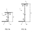
- Figures 2a and 2b show the spar obtained in two sections cross referenced respectively IIA-IIA and IIBIIB, at places shown in Figure Ib.
- FIGs 2a and 2b also show the arrangement of the wings 3 and 4 which give the profile the designation profile in J.
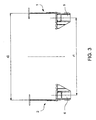
- Figure 3 shows, in a simplified rear view, the two side members 1, 2 and suspension hands 5, 6 fixed respectively on one and the other of the two longitudinal members of a chassis according to the invention.
- Figure 3 nevertheless highlights the best the benefits of using beams prepared according to the invention.
- J-profiles in place of I-profiles allows to give a wider base to the tray or to any other equipment than we want to fix on the chassis. More particularly, this provision ensures better stability in tipping and in circulation. A difference of 15 to 20 cm between a width I1 which would be available when using a profile in I and a width I2 available using J-profiles is completely made doable.
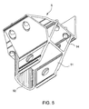
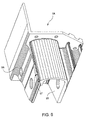
- FIGs 4 and 5 on the one hand, and Figures 6 and 7, on the other hand, show in complementary perspectives, two suspension hands 5 and 5A obtained from profiles in two different versions.
- the first version, the suspension hand 5, represented on the Figures 4 and 5 is obtained from an extruded section 51 of section complex, completed and partially stiffened by a 52-C profile.
- the profile complementary 52 is welded to the profile 51 by a continuous weld 53 as shown in Figure 4.
- the hanging hand 5 as well carried out can be fixed on the side rails, for example, by means of bolts 54.
- the second version, the 5A suspension hand, shown on the Figures 6 and 7 is obtained from two sections 55 and 56. These two profiles are extruded profiles of complex sections. They are cut out as shown in Figures 6 and 7 and assembled with a continuous weld 57 as shown in FIG. 6, and in complement in Figure 7.
- the suspension hand 5A thus produced can be fixed to a beam using bolts.
- the suspension hand 5A like the suspension hand 5, is advantageously attached to the spar by means of rivets 58.
- the chassis with reduced welds according to the invention is advantageously fitted with hydroformed sleepers 61, as shown in FIG. 8. Parts such as a sleeper made in one piece by hydroforming has the advantage of being free of welds.
- the rivets 58 are arranged so as to be able, at least in part, to be used both for fixing on the corresponding spar, a cross-member 7 by one or other of its ends 71, 72 and d 'a suspension hand 5, 6.
- FIG. 8 shows, it is nevertheless possible to use crosspieces 8 supplemented by mounting elements 81 to 83 and an element not shown, the attachment to one and the other of the side members being obtained by means of rivets 58.
Landscapes
- Engineering & Computer Science (AREA)
- Chemical & Material Sciences (AREA)
- Combustion & Propulsion (AREA)
- Transportation (AREA)
- Mechanical Engineering (AREA)
- Body Structure For Vehicles (AREA)
- Pressure Welding/Diffusion-Bonding (AREA)
- Joining Of Corner Units Of Frames Or Wings (AREA)
- Structure Of Receivers (AREA)
- Vehicle Body Suspensions (AREA)
- Butt Welding And Welding Of Specific Article (AREA)
- Glass Compositions (AREA)
- Inorganic Compounds Of Heavy Metals (AREA)
- Production Of Liquid Hydrocarbon Mixture For Refining Petroleum (AREA)
Abstract
Description
- les longerons sont délimités en hauteur, dans la partie de hauteur réduite, par un bord rectiligne aligné avec le bord correspondant de la partie de hauteur initiale et par un bord comportant une partie courbe dans la sens de la norme française ISO 1726 (Liaisons mécaniques entre tracteurs et semi-remorques) ou une partie de toute autre forme, mais non aligné avec le bord correspondant de la partie de hauteur initiale ; dans le cadre de la présente description, le terme " bord du longeron " désigne indifféremment l'aile et les ailes, inférieures et supérieures, d'un longeron en I ou en J ; ce qui importe ici, c'est la forme du longeron en vue latérale ;
- chacun des longerons est pourvu de deux parties de hauteur réduite; chaque partie s'étend respectivement à partir de l'une ou de l'autre des deux extrémités du longeron vers l'intérieur du longeron ;
- chacun des longerons est pourvu de deux parties de hauteur réduite dont les bords rectilignes ne sont pas alignés avec le même bord de la partie de hauteur initiale ;
- les deux longerons sont pourvus, à leur bord inférieur, d'une aile s'étendant à partir de l'âme correspondante, l'une vers l'autre; cette disposition permet de construire des châssis non pas à partir de profilés en I, mais à partir de profilés de J, comme cela sera décrit plus en détail dans la description d'un mode de réalisation de l'invention ;
- le châssis est pourvu de mains de suspension fixées aux longerons par des rivets ;
- le châssis comprend des traverses hydroformées reliant les longerons entre eux ;
- les traverses hydroformées sont fixées aux longerons par des rivets dont au moins quelques uns servent en même temps à la fixation des mains de suspension.
- l'aile et l'âme sont réunis par une soudure unique obtenue par soudage
par friction et s'étendant sur l'âme sensiblement dans le sens de la
longueur du longeron et essentiellement uniquement dans la partie de
hauteur réduite ;
la soudure par friction est effectuée soit par l'utilisation de deux têtes de friction montées en tête bêche et appliquées de part et d'autre de l'âme du profilé ou par l'utilisation d'une seule tête appliquée d'un seul côté en pleine pénétration ; - le longeron est délimité en hauteur, dans la partie de hauteur réduite, par un bord rectiligne aligné avec le bord correspondant de la partie de hauteur initiale et par un bord comportant une partie courbe ou une partie de toute autre forme, mais non aligné avec le bord correspondant de la partie de hauteur initiale, comme cela est décrit plus haut ;
- la soudure unique suit le bord au moins partiellement courbe.
| ALLIAGE | Charge à la rupture Rm minimale | Limite d'élasticité RpO,2 minimale |
| 6082 | 310 | 260 |
| 7003 | 350 | 290 |
| 7005 | 350 | 290 |
| 7020 | 350 | 290 |
| 7022 | 490 | 420 |
| 7049 | 610 | 530 |
| 7075 | 530 | 460 |
En complément de l'utilisation de longerons ayant une soudure unique dans une partie de hauteur réduite, le châssis à soudures réduites selon l'invention est avantageusement équipé de traverses hydroformées 61, comme cela est représenté sur la Figure 8. Des pièces telles une traverse réalisée en une seule pièce par hydroformage présente l'avantage d'être exempte de soudures. Ainsi, en utilisant des traverses hydroformées 7 formées avec des extrémités 71 et 72 adéquates pour être insérées dans et assemblées avec un longeron 1, 2, et en utilisant des rivets 58 pour fixer les traverses 7 sur les longerons 1 et 2, on contribue, de manière supplémentaire, à la mise en oeuvre du principe de l'invention selon lequel on utilise le moins de soudures possibles. Avantageusement, les rivets 58 sont disposés de façon à pouvoir, en partie au moins, servir à la fois à la fixation sur le longeron correspondant, d'une traverse 7 par l'une ou l'autre de ses extrémités 71, 72 et d'une main de suspension 5, 6.
Claims (11)
- Châssis à soudures réduites comprenant deux longerons (1, 2) formés chacun à partir d'un profilé unique de hauteur initiale constante, présentant une âme (10) s'étendant dans un plan défini par une hauteur et une longueur du longeron et deux ailes (3, 4), l'âme (10) de chaque longeron présentant une partie (40) ayant la hauteur initiale du profilé et une partie (34, 44) de hauteur réduit, caractérisé en ce que l'une ou l'autre des ailes (3, 4) et l'âme (10) sont réunis par une soudure (33, 43) obtenue par soudage par friction et qui s'étend sur l'âme sensiblement dans le sens de la longueur du longeron (1, 2) et essentiellement uniquement dans la partie de hauteur réduite.
- Châssis selon la revendication 1 dont les longerons présentent, dans la partie de hauteur réduite, un bord rectiligne (31, 41) aligné avec le bord correspondant de la partie de hauteur initiale et un bord (32, 42) comportant une partie courbe ou ayant toute autre forme, mais non aligné avec le bord correspondant de la partie de hauteur initiale, caractérisé en ce que la soudure (33, 47) suit le bord au moins partiellement courbe (32, 42) à faible distance de l'aile.
- Châssis selon la revendication 1 ou 2, caractérisé en ce que chacun des longerons est pourvu de deux parties (34, 44) de hauteur réduite s'étendant respectivement à partir de l'une et de l'autre des deux extrémités (17, 18) du longeron (12) vers l'intérieur du longeron.
- Châssis selon l'une quelconque des revendications 1 à 3, caractérisé en ce que chacun des longerons est pourvu de deux parties (34, 44) de hauteur réduite dont les bords rectilignes (31, 41) ne sont pas alignés avec le même bord (3 ou 4) de la partie de hauteur initiale du longeron (1, 2).
- Châssis selon l'une quelconque des revendications précédentes, caractérisé en ce que chacun des deux longerons (1, 2) est pourvu à son bord inférieur d'une aile (4) s'étendant à partir de l'âme correspondante vers l'autre longeron.
- Châssis selon l'une quelconque des revendications précédentes, caractérisé en ce qu'il est pourvu de mains de suspension (5, 6) fixées aux longerons (1, 2) par des rivets (58).
- Châssis selon l'une quelconque des revendications précédentes, caractérisé en ce qu'il comprend des traverses hydroformés (7) reliant les longerons (1, 2) entre eux.
- Châssis selon la revendication 7, caractérisé en ce que les traverses hydroformées (7) sont fixées aux longerons par des rivets (8) dont au moins quelques uns servent en même temps à la fixation des mains de suspension (5, 6).
- Longeron pour un châssis à soudures réduites, formé à partir d'un profilé unique de hauteur initiale constante, présentant une âme (10) s'étendant dans un plan défini par une hauteur et une longueur du longeron, et deux ailes (3, 4), l'âme (10) présentant une partie (40) ayant la hauteur initiale du profilé et une partie (34, 44) de hauteur réduite, caractérisé en ce que l'une ou l'autre des ailes (3 ou 4) et l'âme (10) sont réunies par une soudure (33, 43) obtenue par soudage par friction et qui s'étend sur l'âme sensiblement dans le sens de la longueur du longeron (1, 2) et essentiellement uniquement dans la partie de hauteur réduite.
- Longeron selon la revendication 9, présentant dans la partie de hauteur réduite (34, 44), partie de hauteur réduite (34, 44), un bord rectiligne (31, 41) et un bord (32, 42) au moins partiellement courbe ou ayant toute autre forme, mais non aligné avec le bord correspondant de la partie de hauteur initiale, caractérisé en ce que la soudure (33, 43) suit le bord au moins partiellement courbe (32, 42).
- Procédé de fabrication d'un longeron pour un châssis à soudures réduites à partir d'un profilé unique présentant une âme (10) qui s'étend dans un plan défini par une hauteur et une longueur du longeron et au moins une aile (3, 4), caractérisé en ce que l'on pratique dans une partie du profilé qui doit devenir une partie de hauteur réduite du longeron, une découpe de l'âme, en ce que l'on rapproche ensuite les deux parties de l'âme par cintrage de l'une des deux et en ce que l'on réunit ces parties de l'âme par une soudure unique obtenue par soudage par friction et qui s'étend sur l'âme sensiblement dans le sens de la longueur du longeron et essentiellement uniquement dans la partie de hauteur réduite.
Applications Claiming Priority (2)
| Application Number | Priority Date | Filing Date | Title |
|---|---|---|---|
| FR0009740 | 2000-07-25 | ||
| FR0009740A FR2812265B1 (fr) | 2000-07-25 | 2000-07-25 | Chassis a soudures reduites, longeron pour un tel chassis et procede de fabrication d'un tel longeron |
Publications (3)
| Publication Number | Publication Date |
|---|---|
| EP1176086A1 true EP1176086A1 (fr) | 2002-01-30 |
| EP1176086B1 EP1176086B1 (fr) | 2005-05-11 |
| EP1176086B8 EP1176086B8 (fr) | 2005-09-21 |
Family
ID=8852893
Family Applications (1)
| Application Number | Title | Priority Date | Filing Date |
|---|---|---|---|
| EP01401998A Expired - Lifetime EP1176086B8 (fr) | 2000-07-25 | 2001-07-25 | Châssis à soudures réduites, longeron pour un tel châssis et procédé de fabrication d'un tel longeron |
Country Status (6)
| Country | Link |
|---|---|
| EP (1) | EP1176086B8 (fr) |
| AT (1) | ATE295294T1 (fr) |
| DE (1) | DE60110695T2 (fr) |
| ES (1) | ES2240370T3 (fr) |
| FR (1) | FR2812265B1 (fr) |
| PT (1) | PT1176086E (fr) |
Cited By (4)
| Publication number | Priority date | Publication date | Assignee | Title |
|---|---|---|---|---|
| CN107685774A (zh) * | 2017-09-07 | 2018-02-13 | 赵永胜 | 一种通孔加固装置及其实现方法 |
| CN110550108A (zh) * | 2019-07-26 | 2019-12-10 | 浙江飞碟汽车制造有限公司 | 一种用于承载式车身的车身下部结构 |
| CN113022723A (zh) * | 2019-12-24 | 2021-06-25 | 临沂市宇顺机械有限公司 | 一种折叠式爬梯半挂车 |
| CN113428230A (zh) * | 2021-08-27 | 2021-09-24 | 沛县迅驰专用车辆制造有限公司 | 一种半挂车纵梁总成 |
Families Citing this family (3)
| Publication number | Priority date | Publication date | Assignee | Title |
|---|---|---|---|---|
| DE202006010181U1 (de) * | 2006-06-30 | 2007-04-26 | Humbaur Gmbh | Achsverstrebung |
| DE102016107048B4 (de) * | 2016-04-15 | 2021-06-24 | Saf-Holland Gmbh | Rahmeneinheit |
| DE102016109184B4 (de) * | 2016-05-19 | 2018-12-13 | Saf-Holland Gmbh | Haltebock |
Citations (6)
| Publication number | Priority date | Publication date | Assignee | Title |
|---|---|---|---|---|
| US2277616A (en) * | 1941-07-31 | 1942-03-24 | Roy C Townsend | Structural beam |
| US3612569A (en) * | 1969-01-29 | 1971-10-12 | Joseph A Marinelli | Trailer construction |
| US5210921A (en) * | 1992-07-13 | 1993-05-18 | Howard Booher | Method of extruded aluminum contoured beam fabrication |
| US5242185A (en) * | 1992-03-09 | 1993-09-07 | Fruehauf Trailer Corporation | Shallow nose platform trailer |
| US5718048A (en) * | 1994-09-28 | 1998-02-17 | Cosma International Inc. | Method of manufacturing a motor vehicle frame assembly |
| US5725247A (en) * | 1993-10-12 | 1998-03-10 | Ab Volvo | End section of frame member |
-
2000
- 2000-07-25 FR FR0009740A patent/FR2812265B1/fr not_active Expired - Fee Related
-
2001
- 2001-07-25 EP EP01401998A patent/EP1176086B8/fr not_active Expired - Lifetime
- 2001-07-25 ES ES01401998T patent/ES2240370T3/es not_active Expired - Lifetime
- 2001-07-25 DE DE60110695T patent/DE60110695T2/de not_active Expired - Fee Related
- 2001-07-25 PT PT01401998T patent/PT1176086E/pt unknown
- 2001-07-25 AT AT01401998T patent/ATE295294T1/de not_active IP Right Cessation
Patent Citations (6)
| Publication number | Priority date | Publication date | Assignee | Title |
|---|---|---|---|---|
| US2277616A (en) * | 1941-07-31 | 1942-03-24 | Roy C Townsend | Structural beam |
| US3612569A (en) * | 1969-01-29 | 1971-10-12 | Joseph A Marinelli | Trailer construction |
| US5242185A (en) * | 1992-03-09 | 1993-09-07 | Fruehauf Trailer Corporation | Shallow nose platform trailer |
| US5210921A (en) * | 1992-07-13 | 1993-05-18 | Howard Booher | Method of extruded aluminum contoured beam fabrication |
| US5725247A (en) * | 1993-10-12 | 1998-03-10 | Ab Volvo | End section of frame member |
| US5718048A (en) * | 1994-09-28 | 1998-02-17 | Cosma International Inc. | Method of manufacturing a motor vehicle frame assembly |
Cited By (6)
| Publication number | Priority date | Publication date | Assignee | Title |
|---|---|---|---|---|
| CN107685774A (zh) * | 2017-09-07 | 2018-02-13 | 赵永胜 | 一种通孔加固装置及其实现方法 |
| CN110550108A (zh) * | 2019-07-26 | 2019-12-10 | 浙江飞碟汽车制造有限公司 | 一种用于承载式车身的车身下部结构 |
| CN110550108B (zh) * | 2019-07-26 | 2024-05-03 | 山东五征环保科技股份有限公司 | 一种用于承载式车身的车身下部结构 |
| CN113022723A (zh) * | 2019-12-24 | 2021-06-25 | 临沂市宇顺机械有限公司 | 一种折叠式爬梯半挂车 |
| CN113022723B (zh) * | 2019-12-24 | 2024-04-19 | 临沂市宇顺机械有限公司 | 一种折叠式爬梯半挂车 |
| CN113428230A (zh) * | 2021-08-27 | 2021-09-24 | 沛县迅驰专用车辆制造有限公司 | 一种半挂车纵梁总成 |
Also Published As
| Publication number | Publication date |
|---|---|
| ES2240370T3 (es) | 2005-10-16 |
| EP1176086B8 (fr) | 2005-09-21 |
| ATE295294T1 (de) | 2005-05-15 |
| DE60110695D1 (de) | 2005-06-16 |
| PT1176086E (pt) | 2005-09-30 |
| FR2812265A1 (fr) | 2002-02-01 |
| FR2812265B1 (fr) | 2002-12-06 |
| DE60110695T2 (de) | 2006-01-26 |
| EP1176086B1 (fr) | 2005-05-11 |
Similar Documents
| Publication | Publication Date | Title |
|---|---|---|
| EP1378402B2 (fr) | Profilé pour élément de structure de véhicule automobile, et châssis correspondant | |
| EP2137049B1 (fr) | Véhicule comprenant une prolonge avec appui perfectionné | |
| EP3177507B1 (fr) | Structure de véhicule avec renfort entre longeron aluminium et pied avant | |
| FR2914332A1 (fr) | Structure de renforcement de cabine et cabine d'engin de travaux ainsi renforcee | |
| FR2786743A1 (fr) | Procede pour fabriquer une structure de dossier de siege pour vehicule, et structure de dossier obtenue par ce procede | |
| WO2012168612A1 (fr) | Carrosserie de vehicule automobile, comprenant un pied milieu et un arceau central encastre dans le pied milieu | |
| EP1176086B1 (fr) | Châssis à soudures réduites, longeron pour un tel châssis et procédé de fabrication d'un tel longeron | |
| CA2296755A1 (fr) | Paroi laterale pour vehicule ferroviaire et caisse de vehicule ferroviaire correspondante | |
| FR2945267A3 (fr) | Chassis de vehicule automobile et procede de fabrication associe | |
| EP1571079B1 (fr) | Longeron de fuselage pour aéronef et caisson central équipé d'un tel longeron | |
| EP1454776B1 (fr) | Essieu à traverse déformable en torsion et procédé de fabrication de la traverse | |
| EP1595749A1 (fr) | Procédé de fabrication d'une platine de support d'un absorbeur d'énergie d'un pare-chocs et platine de support obtenue par un tel procédé | |
| FR2757090A1 (fr) | Procede de fabrication d'un composant de chassis creux de vehicule ayant un coude bien defini | |
| WO2008061931A1 (fr) | Structure de pied milieu pour vehicule automobile | |
| FR2922179A1 (fr) | Structure de caisse de vehicule automobile et vehicule comportant une telle structure de caisse. | |
| FR2880307A1 (fr) | Glissiere pour siege de vehicule automobile, vehicule comprenant une telle glissiere et procede d'assemblage d'une telle glissiere | |
| EP2030861A2 (fr) | Boggie, notamment pour wagon de transport de marchandises | |
| WO2017098182A1 (fr) | Elément de carrosserie pour véhicule automobile et procédé de fabrication correspondant | |
| EP3299246B1 (fr) | Structure de caisse de véhicule ferroviaire | |
| FR2872787A1 (fr) | Benne pour le transport et/ou le stockage de materiau en vrac | |
| EP3877239B1 (fr) | Agencement avec une structure latérale de véhicule et procédé de réalisation d'un tel agencement | |
| EP1675765B1 (fr) | Structure de pied milieu pour vehicule automobile | |
| BE1010496A3 (fr) | Benne et vehicule la comportant. | |
| FR2900896A1 (fr) | Element de liaison pour realiser un longeron, longeron comportant un tel element et vehicule automobile comportant au moins un tel longeron | |
| FR3160626A1 (fr) | Essieu rigide arrière de véhicule automobile |
Legal Events
| Date | Code | Title | Description |
|---|---|---|---|
| PUAI | Public reference made under article 153(3) epc to a published international application that has entered the european phase |
Free format text: ORIGINAL CODE: 0009012 |
|
| AK | Designated contracting states |
Kind code of ref document: A1 Designated state(s): AT BE CH CY DE DK ES FI FR GB GR IE IT LI LU MC NL PT SE TR |
|
| AX | Request for extension of the european patent |
Free format text: AL;LT;LV;MK;RO;SI |
|
| 17P | Request for examination filed |
Effective date: 20020730 |
|
| AKX | Designation fees paid |
Free format text: AT BE CH CY DE DK ES FI FR GB GR IE IT LI LU MC NL PT SE TR |
|
| GRAP | Despatch of communication of intention to grant a patent |
Free format text: ORIGINAL CODE: EPIDOSNIGR1 |
|
| GRAS | Grant fee paid |
Free format text: ORIGINAL CODE: EPIDOSNIGR3 |
|
| GRAA | (expected) grant |
Free format text: ORIGINAL CODE: 0009210 |
|
| AK | Designated contracting states |
Kind code of ref document: B1 Designated state(s): AT BE CH CY DE DK ES FI FR GB GR IE IT LI LU MC NL PT SE TR |
|
| PG25 | Lapsed in a contracting state [announced via postgrant information from national office to epo] |
Ref country code: IE Free format text: LAPSE BECAUSE OF FAILURE TO SUBMIT A TRANSLATION OF THE DESCRIPTION OR TO PAY THE FEE WITHIN THE PRESCRIBED TIME-LIMIT Effective date: 20050511 Ref country code: FI Free format text: LAPSE BECAUSE OF FAILURE TO SUBMIT A TRANSLATION OF THE DESCRIPTION OR TO PAY THE FEE WITHIN THE PRESCRIBED TIME-LIMIT Effective date: 20050511 Ref country code: AT Free format text: LAPSE BECAUSE OF FAILURE TO SUBMIT A TRANSLATION OF THE DESCRIPTION OR TO PAY THE FEE WITHIN THE PRESCRIBED TIME-LIMIT Effective date: 20050511 Ref country code: TR Free format text: LAPSE BECAUSE OF FAILURE TO SUBMIT A TRANSLATION OF THE DESCRIPTION OR TO PAY THE FEE WITHIN THE PRESCRIBED TIME-LIMIT Effective date: 20050511 |
|
| REG | Reference to a national code |
Ref country code: GB Ref legal event code: FG4D Free format text: NOT ENGLISH |
|
| REG | Reference to a national code |
Ref country code: CH Ref legal event code: EP |
|
| REG | Reference to a national code |
Ref country code: IE Ref legal event code: FG4D Free format text: LANGUAGE OF EP DOCUMENT: FRENCH |
|
| REF | Corresponds to: |
Ref document number: 60110695 Country of ref document: DE Date of ref document: 20050616 Kind code of ref document: P |
|
| RAP2 | Party data changed (patent owner data changed or rights of a patent transferred) |
Owner name: BENALU |
|
| PG25 | Lapsed in a contracting state [announced via postgrant information from national office to epo] |
Ref country code: CY Free format text: LAPSE BECAUSE OF FAILURE TO SUBMIT A TRANSLATION OF THE DESCRIPTION OR TO PAY THE FEE WITHIN THE PRESCRIBED TIME-LIMIT Effective date: 20050725 Ref country code: LU Free format text: LAPSE BECAUSE OF NON-PAYMENT OF DUE FEES Effective date: 20050725 |
|
| REG | Reference to a national code |
Ref country code: CH Ref legal event code: NV Representative=s name: KIRKER & CIE SA |
|
| PG25 | Lapsed in a contracting state [announced via postgrant information from national office to epo] |
Ref country code: MC Free format text: LAPSE BECAUSE OF NON-PAYMENT OF DUE FEES Effective date: 20050731 |
|
| PG25 | Lapsed in a contracting state [announced via postgrant information from national office to epo] |
Ref country code: SE Free format text: LAPSE BECAUSE OF FAILURE TO SUBMIT A TRANSLATION OF THE DESCRIPTION OR TO PAY THE FEE WITHIN THE PRESCRIBED TIME-LIMIT Effective date: 20050811 Ref country code: GR Free format text: LAPSE BECAUSE OF FAILURE TO SUBMIT A TRANSLATION OF THE DESCRIPTION OR TO PAY THE FEE WITHIN THE PRESCRIBED TIME-LIMIT Effective date: 20050811 Ref country code: DK Free format text: LAPSE BECAUSE OF FAILURE TO SUBMIT A TRANSLATION OF THE DESCRIPTION OR TO PAY THE FEE WITHIN THE PRESCRIBED TIME-LIMIT Effective date: 20050811 |
|
| NLT2 | Nl: modifications (of names), taken from the european patent patent bulletin |
Owner name: BENALU Effective date: 20050706 |
|
| REG | Reference to a national code |
Ref country code: PT Ref legal event code: SC4A Effective date: 20050715 |
|
| GBT | Gb: translation of ep patent filed (gb section 77(6)(a)/1977) |
Effective date: 20050914 |
|
| REG | Reference to a national code |
Ref country code: ES Ref legal event code: FG2A Ref document number: 2240370 Country of ref document: ES Kind code of ref document: T3 |
|
| REG | Reference to a national code |
Ref country code: IE Ref legal event code: FD4D |
|
| PLBE | No opposition filed within time limit |
Free format text: ORIGINAL CODE: 0009261 |
|
| STAA | Information on the status of an ep patent application or granted ep patent |
Free format text: STATUS: NO OPPOSITION FILED WITHIN TIME LIMIT |
|
| 26N | No opposition filed |
Effective date: 20060214 |
|
| PGFP | Annual fee paid to national office [announced via postgrant information from national office to epo] |
Ref country code: PT Payment date: 20080625 Year of fee payment: 8 |
|
| PGFP | Annual fee paid to national office [announced via postgrant information from national office to epo] |
Ref country code: CH Payment date: 20080708 Year of fee payment: 8 Ref country code: DE Payment date: 20080730 Year of fee payment: 8 Ref country code: ES Payment date: 20080718 Year of fee payment: 8 |
|
| PGFP | Annual fee paid to national office [announced via postgrant information from national office to epo] |
Ref country code: FR Payment date: 20080730 Year of fee payment: 8 Ref country code: IT Payment date: 20080717 Year of fee payment: 8 Ref country code: NL Payment date: 20080711 Year of fee payment: 8 |
|
| PGFP | Annual fee paid to national office [announced via postgrant information from national office to epo] |
Ref country code: GB Payment date: 20080630 Year of fee payment: 8 |
|
| PGFP | Annual fee paid to national office [announced via postgrant information from national office to epo] |
Ref country code: BE Payment date: 20080722 Year of fee payment: 8 |
|
| BERE | Be: lapsed |
Owner name: *BENALU Effective date: 20090731 |
|
| REG | Reference to a national code |
Ref country code: PT Ref legal event code: MM4A Free format text: LAPSE DUE TO NON-PAYMENT OF FEES Effective date: 20100125 |
|
| REG | Reference to a national code |
Ref country code: CH Ref legal event code: PL |
|
| GBPC | Gb: european patent ceased through non-payment of renewal fee |
Effective date: 20090725 |
|
| NLV4 | Nl: lapsed or anulled due to non-payment of the annual fee |
Effective date: 20100201 |
|
| REG | Reference to a national code |
Ref country code: FR Ref legal event code: ST Effective date: 20100331 |
|
| PG25 | Lapsed in a contracting state [announced via postgrant information from national office to epo] |
Ref country code: FR Free format text: LAPSE BECAUSE OF NON-PAYMENT OF DUE FEES Effective date: 20090731 Ref country code: PT Free format text: LAPSE BECAUSE OF NON-PAYMENT OF DUE FEES Effective date: 20100125 Ref country code: LI Free format text: LAPSE BECAUSE OF NON-PAYMENT OF DUE FEES Effective date: 20090731 Ref country code: CH Free format text: LAPSE BECAUSE OF NON-PAYMENT OF DUE FEES Effective date: 20090731 |
|
| PG25 | Lapsed in a contracting state [announced via postgrant information from national office to epo] |
Ref country code: GB Free format text: LAPSE BECAUSE OF NON-PAYMENT OF DUE FEES Effective date: 20090725 |
|
| PG25 | Lapsed in a contracting state [announced via postgrant information from national office to epo] |
Ref country code: DE Free format text: LAPSE BECAUSE OF NON-PAYMENT OF DUE FEES Effective date: 20100202 Ref country code: BE Free format text: LAPSE BECAUSE OF NON-PAYMENT OF DUE FEES Effective date: 20090731 |
|
| REG | Reference to a national code |
Ref country code: ES Ref legal event code: FD2A Effective date: 20090727 |
|
| PG25 | Lapsed in a contracting state [announced via postgrant information from national office to epo] |
Ref country code: ES Free format text: LAPSE BECAUSE OF NON-PAYMENT OF DUE FEES Effective date: 20090727 |
|
| PG25 | Lapsed in a contracting state [announced via postgrant information from national office to epo] |
Ref country code: IT Free format text: LAPSE BECAUSE OF NON-PAYMENT OF DUE FEES Effective date: 20090725 |
|
| PG25 | Lapsed in a contracting state [announced via postgrant information from national office to epo] |
Ref country code: NL Free format text: LAPSE BECAUSE OF NON-PAYMENT OF DUE FEES Effective date: 20100201 |