EP1175969A2 - Structure and method for fitting magazine to nose member of nailing machine - Google Patents
Structure and method for fitting magazine to nose member of nailing machine Download PDFInfo
- Publication number
- EP1175969A2 EP1175969A2 EP01117946A EP01117946A EP1175969A2 EP 1175969 A2 EP1175969 A2 EP 1175969A2 EP 01117946 A EP01117946 A EP 01117946A EP 01117946 A EP01117946 A EP 01117946A EP 1175969 A2 EP1175969 A2 EP 1175969A2
- Authority
- EP
- European Patent Office
- Prior art keywords
- magazine
- nose member
- nailing machine
- clearance
- nose
- Prior art date
- Legal status (The legal status is an assumption and is not a legal conclusion. Google has not performed a legal analysis and makes no representation as to the accuracy of the status listed.)
- Granted
Links
- 238000000034 method Methods 0.000 title claims description 12
- 229920003002 synthetic resin Polymers 0.000 claims description 2
- 239000000057 synthetic resin Substances 0.000 claims description 2
- 238000003780 insertion Methods 0.000 description 5
- 230000037431 insertion Effects 0.000 description 5
- XAGFODPZIPBFFR-UHFFFAOYSA-N aluminium Chemical compound [Al] XAGFODPZIPBFFR-UHFFFAOYSA-N 0.000 description 2
- 229910052782 aluminium Inorganic materials 0.000 description 2
- 239000013013 elastic material Substances 0.000 description 2
- 238000012986 modification Methods 0.000 description 1
- 230000004048 modification Effects 0.000 description 1
- 238000000465 moulding Methods 0.000 description 1
Images

Classifications
-
- B—PERFORMING OPERATIONS; TRANSPORTING
- B25—HAND TOOLS; PORTABLE POWER-DRIVEN TOOLS; MANIPULATORS
- B25C—HAND-HELD NAILING OR STAPLING TOOLS; MANUALLY OPERATED PORTABLE STAPLING TOOLS
- B25C1/00—Hand-held nailing tools; Nail feeding devices
- B25C1/001—Nail feeding devices
- B25C1/005—Nail feeding devices for rows of contiguous nails
Definitions
- the present invention relates to a method for fitting a magazine to a nose member, for driving a nail, disposed on the leading end portion of a nailing machine. Further, the present invention relates to a structure of a nailing machine and a nailing machine including the structure.
- a nailing machine is provided with a nose member on the leading end portion thereof.
- the nose member is used not only to guide a nail hammering driver in a slidable manner but also to drive out a nail.
- a magazine in the shape of a straight-sheath is provided so that connected nails loaded into the magazine can be supplied from an opening formed on one side of the nose member. Further, the nose member and the magazine are molded separately from each other, and the magazine is fixed to the nose member.
- the nose member is molded with lost wax process.
- the magazine is composed of an extruded member made of aluminum. That is, since the nose member and the magazine are produced according to different forming methods, it is difficult to accurately fit the dimensions of them to each other. When the magazine is fixed to the nose member by using a bolt, it needs a dimensional tolerance between the nose member and the magazine. Therefore, there inevitably appears a clearance between the nose member and the magazine.
- this clearance causes vibrations when a nailing machine is used. That is, each time the nailing machine drives a nail, the nailing machine bounces up from the surface of a driven member due to reaction caused by the driving operation. As a result, the magazine is greatly shaken and vibrated due to the impulse caused by the bouncing nailing machine, thereby causing the nose member and magazine to rattle with respect to each other. Thus, if such vibrations occur repeatedly, there is a possibility that the magazine may be broken.
- the present invention aims at eliminating the above drawbacks. Accordingly, it is an object of the present invention to provide a method for fitting a magazine to the nose member of a nailing machine, which not only provides a clearance as an allowance for a dimensional tolerance between the nose member and the magazine, but also eliminates a possibility that the magazine can be broken due to mutual vibration and rattle between the nose member and the magazine caused by the nail driving operation. Further, the present invention aims at providing a nailing machine and its structure, which eliminate the above drawbacks.
- the nailing machine includes the nose member disposed in the leading end portion of a main body, and the straight-sheath-shaped magazine, which is mounted in an opening formed in the side surface of the nose member for supplying sequentially the connected nails to the nose member.
- an elastic member is pressed in into a clearance provided between the nose member and the magazine, when the magazine is fit to the nose member.
- the present invention also provides a structure for a nailing machine including a main body, a nose member having a damper receiving portion provided in an upper end portion thereof, and a magazine.
- the structure includes at least one clearance provided between the nose member and the magazine, wherein an elastic member is pressed in into said clearance.
- the present invention provides a nailing machine including the above structure.
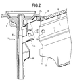
- reference character 1 designates a nose member which is disposed on the leading end portion of a nailing machine, and 2 stands for a magazine.
- the nose member 1 is disposed on the leading end portion of a main body of the nailing machine and is used to drive the leading nail N of stick-shaped connected nails supplied thereto.
- the nose member 1 is molded with lost wax process and includes a dish-shaped damper receiving portion 3, which is formed in the upper end portion thereof, and a cylindrical-shaped portion 4, which is extended downward from the central portion of the damper receiving portion 3.
- a driver 5 for driving a nail is slidably stored in the cylindrical-shaped portion 4.
- a main body of the nailing machine is disposed.
- a hammering mechanism is disposed; and, this hammering mechanism can drive the driver 5 for driving a nail.
- the structures of these components are the same as those of a conventional nailing machine; therefore, the description thereof is omitted here.
- the cylindrical-shaped portion 4 is opened on one side thereof.
- a pair of mounting pieces 7, 7 as well as a pair of mounting pieces 8, 8, are disposed laterally.
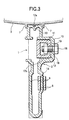
- a bolt receiving portion 11 having a rectangular-shaped section is formed projectingly. Outside the bolt-receiving portion 11, a bolt insertion hole 12 is formed.
- the magazine 2 is an extruded member of aluminum and is shaped like a straight sheath for storing stick-shaped connected nails therein.
- the magazine 2 is to be connected to the opening 6 formed on one side of the nose member 1 and is able to supply the connected nails to the nose member 1 sequentially.
- a pusher is disposed for pushing out the connected nails to the side toward the nose member 1.
- fitting portions 13, 14, are respectively formed.
- a projecting portion 15 is disposed, which extends in the longitudinal direction of the magazine 2 and has a substantially U-shaped section.
- a bolt insertion hole 16 is formed, which corresponds to the bolt insertion hole of the bolt receiving portion 11.
- the fixing means is not limited to the above-mentioned bolt 18 and nut 19, but other known means can be adopted.
- the elastic members 17a, 17b are disposed at the positions shown in Figs. 1 and 3.
- the elastic member 17a disposed at the upper position if the distance between the elastic member 17a and the center of the fixed portion between the nose member 1 and the magazine 2 is set longer, a moment can be made large when vibration with shaking occurs with making the fixed portion as its center. Therefore, vibration can be effectively suppressed.
- the elastic member 17b, disposed at the lower position is disposed at a position symmetrical with the elastic member 17a with respect to the fixed portion. This is because the elastic member 17b as shown in the figures is disposed where it can be fit most easily. Moreover, the effect of disposing the elastic member 17b can be obtained without any problems.
- the elastic members 17a, 17b are pressed in into the clearance between the nose member 1 and the magazine 2, and the nose member 1 and the magazine 2 are disposed in the surfaces which are opposed to each other in the vertical direction. Therefore, even if the magazine 2 is shaken and vibrated about the fixing bolt 18 with respect to the nose member 1 in the nail driving operation, the above-mentioned vibrations can be dampened effectively and the magazine 2 can be positively prevented from breakage.
- the nose member 1 and magazine 2 can be produced at a low cost and with high efficiency.
- the elastic members 17a, 17b may be formed of an elastic material; that is, not only rubber but also synthetic resin can be used as the elastic material of the elastic members 17a, 17b.
- the mounting positions of the elastic members 17a, 17b are not limited to the positions specified in the illustrated embodiment but the elastic members 17a, 17b can disposed at other positions, provided that the positions are capable of absorbing the clearance between the nose member 1 and magazine 2.
Landscapes
- Engineering & Computer Science (AREA)
- Mechanical Engineering (AREA)
- Portable Nailing Machines And Staplers (AREA)
Abstract
Description
Claims (12)
- A method for fitting a nailing machine including a main body, a nose member having an opening formed on a side surface thereof and disposed in a leading end portion of the main body for driving one of connected nails, and a magazine mounted in the opening of the nose member for sequentially supplying the connected nails to the nose member, said method comprising:
fitting the magazine into the nose member, wherein an elastic member is pressed in into a clearance provided between the nose member and the magazine. - The method for fitting a nailing machine according to claim 1, further comprising:
sticking the elastic member on the magazine before fitting the magazine to the nose member. - A structure of a nailing machine including a main body, a nose member having an opening formed on a side surface thereof and disposed in a leading end portion of the main body for driving one of connected nails, and a magazine mounted in the opening of the nose member, said structure comprising:wherein at least one elastic member is pressed in into said clearance.at least one clearance provided between the nose member and the magazine,
- The structure of a nailing machine according to claim 3,
wherein said clearance is provided between the magazine and a damper receiving portion provided in an upper end portion of the nose member. - The structure of a nailing machine according to claim 3,
wherein the magazine is fit to the nose member by connecting a projecting portion of the magazine to a bolt receiving portion of the nose member with a fixing bolt and a nut, and
wherein said clearance is provided between the bolt receiving portion and an inside of the projecting portion. - The structure of a nailing machine according to claim 3,
wherein the magazine is fit to the nose member by connecting a projecting portion of the magazine to a bolt receiving portion of the nose member with a fixing bolt and a nut, and
wherein a first clearance is provided between the magazine and a damper receiving portion provided in an upper end portion of the nose member, and
wherein a second clearance is provided between the bolt receiving portion and an inside of the projecting portion. - The structure of a nailing machine according to Claim 3, wherein the elastic member is made of rubber.
- The structure of a nailing machine according to Claim 3, wherein the elastic member is made of synthetic resin.
- A nailing machine comprising:wherein said elastic member is pressed in into a clearance provided between said nose member and said magazine.a main body;a nose member having an opening formed on a side surface thereof and disposed in a leading end portion of the main body for driving one of connected nails;a magazine mounted in the opening of said nose member; andan elastic member,
- The nailing machine according to Claim 9,
wherein said nose member includes a damper receiving portion provided in an upper end portion of said
wherein the clearance is provided between the magazine and the damper receiving portion of the nose member. - The nailing machine according to Claim 9,
wherein said magazine is fit to said nose member by connecting a projecting portion of said magazine to a bolt receiving portion of said nose member with a fixing bolt and a nut, and
wherein the clearance is provided between the bolt receiving portion and an inside of the projecting portion. - The nailing machine according to Claim 9,
wherein said magazine is fit to said nose member by connecting a projecting portion of said magazine to a bolt receiving portion of said nose member with a fixing bolt and a nut, and
wherein a first clearance is provided between said magazine and a damper receiving portion provided in an upper end portion of said nose member, and
wherein a second clearance is provided between the bolt receiving portion and an inside of the projecting portion.
Applications Claiming Priority (2)
| Application Number | Priority Date | Filing Date | Title |
|---|---|---|---|
| JP2000224446 | 2000-07-25 | ||
| JP2000224446A JP4465831B2 (en) | 2000-07-25 | 2000-07-25 | Method of assembling the magazine to the nose member of the nailing machine |
Publications (3)
| Publication Number | Publication Date |
|---|---|
| EP1175969A2 true EP1175969A2 (en) | 2002-01-30 |
| EP1175969A3 EP1175969A3 (en) | 2005-07-20 |
| EP1175969B1 EP1175969B1 (en) | 2008-09-10 |
Family
ID=18718409
Family Applications (1)
| Application Number | Title | Priority Date | Filing Date |
|---|---|---|---|
| EP01117946A Expired - Lifetime EP1175969B1 (en) | 2000-07-25 | 2001-07-24 | Structure and method for fitting magazine to nose member of nailing machine |
Country Status (5)
| Country | Link |
|---|---|
| US (1) | US6644531B2 (en) |
| EP (1) | EP1175969B1 (en) |
| JP (1) | JP4465831B2 (en) |
| DE (1) | DE60135708D1 (en) |
| TW (1) | TW504437B (en) |
Families Citing this family (6)
| Publication number | Priority date | Publication date | Assignee | Title |
|---|---|---|---|---|
| JP4618537B2 (en) * | 2004-07-15 | 2011-01-26 | 日立工機株式会社 | Nailer |
| JP4802597B2 (en) * | 2005-08-10 | 2011-10-26 | マックス株式会社 | Assembling structure of magazine to nose member of nailing machine |
| US20070278276A1 (en) * | 2006-06-05 | 2007-12-06 | Wan-Fu Wen | Nailing Tool with Displacable Discharge Tube |
| US7549562B2 (en) * | 2007-09-17 | 2009-06-23 | De Poan Pneumatic Corp. | Nail pusher locating device for magazine assembly |
| JP5280181B2 (en) * | 2008-12-18 | 2013-09-04 | 株式会社マキタ | Driving tool |
| JP2025075967A (en) * | 2023-11-01 | 2025-05-15 | 株式会社マキタ | Driving tools |
Family Cites Families (7)
| Publication number | Priority date | Publication date | Assignee | Title |
|---|---|---|---|---|
| US3905535A (en) * | 1973-09-13 | 1975-09-16 | Duo Fast Corp | Fastener driving tool |
| US4197974A (en) * | 1978-06-12 | 1980-04-15 | Speedfast Corporation | Nailer |
| DE3119576A1 (en) * | 1981-05-16 | 1982-12-09 | Joh. Friedrich Behrens AG, 2070 Ahrensburg | Magazine for driving-in tools |
| US4585154A (en) * | 1984-03-26 | 1986-04-29 | Bostitch Division Of Textron Inc. | Fastener driving tool with adjustable three-part magazine canister assembly |
| US4597517A (en) * | 1985-06-21 | 1986-07-01 | Signode Corporation | Magazine interlock for a fastener driving device |
| DE3806626C2 (en) * | 1988-03-02 | 1997-04-24 | Hilti Ag | Powder-powered setting tool |
| US5083694A (en) * | 1991-06-11 | 1992-01-28 | Stanley-Bostitch, Inc. | Fastener driving device with sequential actuation trigger assembly |
-
2000
- 2000-07-25 JP JP2000224446A patent/JP4465831B2/en not_active Expired - Lifetime
-
2001
- 2001-07-24 EP EP01117946A patent/EP1175969B1/en not_active Expired - Lifetime
- 2001-07-24 DE DE60135708T patent/DE60135708D1/en not_active Expired - Lifetime
- 2001-07-25 US US09/911,423 patent/US6644531B2/en not_active Expired - Lifetime
- 2001-07-25 TW TW090118160A patent/TW504437B/en not_active IP Right Cessation
Also Published As
| Publication number | Publication date |
|---|---|
| TW504437B (en) | 2002-10-01 |
| EP1175969B1 (en) | 2008-09-10 |
| DE60135708D1 (en) | 2008-10-23 |
| JP2002036138A (en) | 2002-02-05 |
| EP1175969A3 (en) | 2005-07-20 |
| US6644531B2 (en) | 2003-11-11 |
| JP4465831B2 (en) | 2010-05-26 |
| US20020014511A1 (en) | 2002-02-07 |
Similar Documents
| Publication | Publication Date | Title |
|---|---|---|
| US5816469A (en) | Fastener driving machine | |
| US20080196222A1 (en) | Plastic Fastener | |
| US5332141A (en) | Nailing machine | |
| US6644531B2 (en) | Structure and method for fitting magazine to nose member of nailing machine | |
| US5688006A (en) | Bumper assembly with extension panel | |
| JP4111085B2 (en) | Nailer | |
| JP2019188961A (en) | Bumper fastening structure | |
| EP1033497B1 (en) | Nailer and bumper provided therein for braking impact piston | |
| JP2000159038A (en) | Mounting structure of bumper and grill | |
| US7070081B2 (en) | Driver guides for use with fastener-driving tools and fastener-driving tools having such driver guides | |
| KR100898258B1 (en) | Vehicle door trim mounting structure | |
| US7746281B2 (en) | Antenna mounting assembly | |
| WO2015004822A1 (en) | Window regulator comprising wire tension increasing means | |
| JP5135786B2 (en) | Fastening tool | |
| JP4802597B2 (en) | Assembling structure of magazine to nose member of nailing machine | |
| JP2022012717A (en) | clip | |
| JP2006105338A (en) | Engine mount device | |
| JP6363775B2 (en) | Lighting device mounting structure | |
| US20060181752A1 (en) | Elastic device for a scanning device | |
| JP2007211871A (en) | Fixing structure for fixing parts to the door panel | |
| KR200193289Y1 (en) | A chisel for hammer drill | |
| JP2023111461A (en) | work machine | |
| JP2008024083A (en) | Bumper mounting structure | |
| JP2005291265A (en) | Part tightening structure by resin-made claw | |
| JP2018144816A (en) | Lighting device mounting structure |
Legal Events
| Date | Code | Title | Description |
|---|---|---|---|
| PUAI | Public reference made under article 153(3) epc to a published international application that has entered the european phase |
Free format text: ORIGINAL CODE: 0009012 |
|
| AK | Designated contracting states |
Kind code of ref document: A2 Designated state(s): AT BE CH CY DE DK ES FI FR GB GR IE IT LI LU MC NL PT SE TR |
|
| AX | Request for extension of the european patent |
Free format text: AL;LT;LV;MK;RO;SI |
|
| RIC1 | Information provided on ipc code assigned before grant |
Ipc: 7B 25F 5/00 B Ipc: 7B 25C 1/00 A |
|
| PUAL | Search report despatched |
Free format text: ORIGINAL CODE: 0009013 |
|
| AK | Designated contracting states |
Kind code of ref document: A3 Designated state(s): AT BE CH CY DE DK ES FI FR GB GR IE IT LI LU MC NL PT SE TR |
|
| AX | Request for extension of the european patent |
Extension state: AL LT LV MK RO SI |
|
| 17P | Request for examination filed |
Effective date: 20050824 |
|
| AKX | Designation fees paid |
Designated state(s): DE FR GB |
|
| RBV | Designated contracting states (corrected) |
Designated state(s): DE FR GB |
|
| 17Q | First examination report despatched |
Effective date: 20070212 |
|
| GRAP | Despatch of communication of intention to grant a patent |
Free format text: ORIGINAL CODE: EPIDOSNIGR1 |
|
| GRAS | Grant fee paid |
Free format text: ORIGINAL CODE: EPIDOSNIGR3 |
|
| GRAA | (expected) grant |
Free format text: ORIGINAL CODE: 0009210 |
|
| AK | Designated contracting states |
Kind code of ref document: B1 Designated state(s): DE FR GB |
|
| REG | Reference to a national code |
Ref country code: GB Ref legal event code: FG4D |
|
| REF | Corresponds to: |
Ref document number: 60135708 Country of ref document: DE Date of ref document: 20081023 Kind code of ref document: P |
|
| PLBE | No opposition filed within time limit |
Free format text: ORIGINAL CODE: 0009261 |
|
| STAA | Information on the status of an ep patent application or granted ep patent |
Free format text: STATUS: NO OPPOSITION FILED WITHIN TIME LIMIT |
|
| 26N | No opposition filed |
Effective date: 20090611 |
|
| PGFP | Annual fee paid to national office [announced via postgrant information from national office to epo] |
Ref country code: FR Payment date: 20090710 Year of fee payment: 9 |
|
| PGFP | Annual fee paid to national office [announced via postgrant information from national office to epo] |
Ref country code: GB Payment date: 20090722 Year of fee payment: 9 |
|
| GBPC | Gb: european patent ceased through non-payment of renewal fee |
Effective date: 20100724 |
|
| REG | Reference to a national code |
Ref country code: FR Ref legal event code: ST Effective date: 20110331 |
|
| PG25 | Lapsed in a contracting state [announced via postgrant information from national office to epo] |
Ref country code: FR Free format text: LAPSE BECAUSE OF NON-PAYMENT OF DUE FEES Effective date: 20100802 |
|
| PG25 | Lapsed in a contracting state [announced via postgrant information from national office to epo] |
Ref country code: GB Free format text: LAPSE BECAUSE OF NON-PAYMENT OF DUE FEES Effective date: 20100724 |
|
| PGFP | Annual fee paid to national office [announced via postgrant information from national office to epo] |
Ref country code: DE Payment date: 20200714 Year of fee payment: 20 |
|
| REG | Reference to a national code |
Ref country code: DE Ref legal event code: R071 Ref document number: 60135708 Country of ref document: DE |