EP1175956B1 - Article métallique avec anneau integral en compression à l' extrémité et procédé de fabrication - Google Patents
Article métallique avec anneau integral en compression à l' extrémité et procédé de fabrication Download PDFInfo
- Publication number
- EP1175956B1 EP1175956B1 EP01306416A EP01306416A EP1175956B1 EP 1175956 B1 EP1175956 B1 EP 1175956B1 EP 01306416 A EP01306416 A EP 01306416A EP 01306416 A EP01306416 A EP 01306416A EP 1175956 B1 EP1175956 B1 EP 1175956B1
- Authority
- EP
- European Patent Office
- Prior art keywords
- airfoil
- band
- tip portion
- depth
- compressive stress
- Prior art date
- Legal status (The legal status is an assumption and is not a legal conclusion. Google has not performed a legal analysis and makes no representation as to the accuracy of the status listed.)
- Expired - Lifetime
Links
Images
Classifications
-
- F—MECHANICAL ENGINEERING; LIGHTING; HEATING; WEAPONS; BLASTING
- F01—MACHINES OR ENGINES IN GENERAL; ENGINE PLANTS IN GENERAL; STEAM ENGINES
- F01D—NON-POSITIVE DISPLACEMENT MACHINES OR ENGINES, e.g. STEAM TURBINES
- F01D5/00—Blades; Blade-carrying members; Heating, heat-insulating, cooling or antivibration means on the blades or the members
- F01D5/12—Blades
- F01D5/14—Form or construction
- F01D5/20—Specially-shaped blade tips to seal space between tips and stator
-
- B—PERFORMING OPERATIONS; TRANSPORTING
- B23—MACHINE TOOLS; METAL-WORKING NOT OTHERWISE PROVIDED FOR
- B23P—METAL-WORKING NOT OTHERWISE PROVIDED FOR; COMBINED OPERATIONS; UNIVERSAL MACHINE TOOLS
- B23P9/00—Treating or finishing surfaces mechanically, with or without calibrating, primarily to resist wear or impact, e.g. smoothing or roughening turbine blades or bearings; Features of such surfaces not otherwise provided for, their treatment being unspecified
- B23P9/02—Treating or finishing by applying pressure, e.g. knurling
-
- B—PERFORMING OPERATIONS; TRANSPORTING
- B24—GRINDING; POLISHING
- B24B—MACHINES, DEVICES, OR PROCESSES FOR GRINDING OR POLISHING; DRESSING OR CONDITIONING OF ABRADING SURFACES; FEEDING OF GRINDING, POLISHING, OR LAPPING AGENTS
- B24B39/00—Burnishing machines or devices, i.e. requiring pressure members for compacting the surface zone; Accessories therefor
-
- C—CHEMISTRY; METALLURGY
- C21—METALLURGY OF IRON
- C21D—MODIFYING THE PHYSICAL STRUCTURE OF FERROUS METALS; GENERAL DEVICES FOR HEAT TREATMENT OF FERROUS OR NON-FERROUS METALS OR ALLOYS; MAKING METAL MALLEABLE, e.g. BY DECARBURISATION OR TEMPERING
- C21D7/00—Modifying the physical properties of iron or steel by deformation
- C21D7/02—Modifying the physical properties of iron or steel by deformation by cold working
- C21D7/04—Modifying the physical properties of iron or steel by deformation by cold working of the surface
-
- F—MECHANICAL ENGINEERING; LIGHTING; HEATING; WEAPONS; BLASTING
- F01—MACHINES OR ENGINES IN GENERAL; ENGINE PLANTS IN GENERAL; STEAM ENGINES
- F01D—NON-POSITIVE DISPLACEMENT MACHINES OR ENGINES, e.g. STEAM TURBINES
- F01D5/00—Blades; Blade-carrying members; Heating, heat-insulating, cooling or antivibration means on the blades or the members
- F01D5/12—Blades
- F01D5/28—Selecting particular materials; Particular measures relating thereto; Measures against erosion or corrosion
- F01D5/286—Particular treatment of blades, e.g. to increase durability or resistance against corrosion or erosion
-
- C—CHEMISTRY; METALLURGY
- C21—METALLURGY OF IRON
- C21D—MODIFYING THE PHYSICAL STRUCTURE OF FERROUS METALS; GENERAL DEVICES FOR HEAT TREATMENT OF FERROUS OR NON-FERROUS METALS OR ALLOYS; MAKING METAL MALLEABLE, e.g. BY DECARBURISATION OR TEMPERING
- C21D2221/00—Treating localised areas of an article
- C21D2221/01—End parts (e.g. leading, trailing end)
-
- C—CHEMISTRY; METALLURGY
- C21—METALLURGY OF IRON
- C21D—MODIFYING THE PHYSICAL STRUCTURE OF FERROUS METALS; GENERAL DEVICES FOR HEAT TREATMENT OF FERROUS OR NON-FERROUS METALS OR ALLOYS; MAKING METAL MALLEABLE, e.g. BY DECARBURISATION OR TEMPERING
- C21D2221/00—Treating localised areas of an article
- C21D2221/02—Edge parts
-
- Y—GENERAL TAGGING OF NEW TECHNOLOGICAL DEVELOPMENTS; GENERAL TAGGING OF CROSS-SECTIONAL TECHNOLOGIES SPANNING OVER SEVERAL SECTIONS OF THE IPC; TECHNICAL SUBJECTS COVERED BY FORMER USPC CROSS-REFERENCE ART COLLECTIONS [XRACs] AND DIGESTS
- Y10—TECHNICAL SUBJECTS COVERED BY FORMER USPC
- Y10T—TECHNICAL SUBJECTS COVERED BY FORMER US CLASSIFICATION
- Y10T29/00—Metal working
- Y10T29/49—Method of mechanical manufacture
- Y10T29/49316—Impeller making
- Y10T29/49336—Blade making
Landscapes
- Engineering & Computer Science (AREA)
- Mechanical Engineering (AREA)
- Chemical & Material Sciences (AREA)
- General Engineering & Computer Science (AREA)
- Materials Engineering (AREA)
- Crystallography & Structural Chemistry (AREA)
- Metallurgy (AREA)
- Organic Chemistry (AREA)
- Structures Of Non-Positive Displacement Pumps (AREA)
- Turbine Rotor Nozzle Sealing (AREA)
- Clamps And Clips (AREA)
Claims (8)
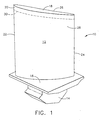
- Elément d'aubage (10) en matériau métallique, l'élément d'aubage (10) comprenant :un élément profilé (12) ; etune partie d'extrémité (18) intégrée à l'élément profilé (12) ;la partie d'extrémité (18) comprenant une bande (20) de matériau métallique sur toute la section transversale de la partie d'extrémité (18) ;la bande (20) subissant un effort de compression supérieur à l'élément profilé (12) et caractérisé en ce que :la bande (20) s'étend dans l'élément profilé (12) jusqu'à une profondeur (30) inférieure à une position au niveau de laquelle une quantité d'effort de traction dans l'élément profilé (12) nécessaire pour compenser l'effort de compression dans la bande (20) est nuisible dans au moins un mode de réponse vibratoire propre à l'élément profilé (12).
- Elément d'aubage (10) selon la revendication 1, dans lequel :le matériau métallique est un alliage à base d'au moins un élément choisi dans l'ensemble comprenant Ti, Fe, Ni et Co ;la bande (20) s'étend radialement dans l'élément profilé (12) jusqu'à une profondeur (30) sélectionnée d'après l'expérience en fonctionnement pour résister aux dégâts en fonctionnement.
- Elément d'aubage (10) selon la revendication 2, dans lequel la position est supérieure à environ 10 % d'une longueur de portée de l'élément profilé (12).
- Procédé de fabrication d'un élément d'aubage (10) en matériau métallique, l'élément d'aubage comprenant un élément profilé (12) et une partie d'extrémité (18) intégrée à l'élément profilé (12), la partie d'extrémité (18) comprenant une bande (20) de matériau métallique sur toute la section transversale de la partie d'extrémité (18) et intégrée à et dans l'élément profilé (12), la bande subissant un effort de compression supérieur à l'élément profilé, caractérisé par les étapes consistant à :effectuer une déformation au rouleau sur la partie d'extrémité (18) jusqu'à la profondeur dans la partie d'extrémité (18) jusqu'à ce que l'effort de compression soit présent dans toute la section transversale de la partie d'extrémité (18), etchoisir une profondeur de la bande dans la partie d'extrémité de façon à ce qu'elle soit inférieure à une position au niveau de laquelle une quantité excessive et nuisible d'effort de traction résiduel dans l'élément profilé (12) est nécessaire pour compenser l'effort de compression dans la bande (20), mesuré dans au moins un mode de réponse vibratoire propre à l'élément profilé (12).
- Procédé selon la revendication 4, dans lequel la profondeur de la bande (20) est sélectionnée en inspectant l'élément profilé (12) d'un élément d'aubage (10) endommagé en fonctionnement et en fournissant la profondeur suffisante pour résister aux dégâts en fonctionnement.
- Procédé selon la revendication 4, dans lequel la position est supérieure à environ 10 % d'une longueur de portée de l'élément profilé (12).
- Procédé selon la revendication 4 pour former l'élément profilé d'un élément d'aubage, dans lequel :le matériau métallique est un alliage à base d'au moins un élément choisi dans l'ensemble comprenant Ti, Fe, Ni et Co ; etl'effort de compression se trouve dans la plage d'environ 68 947 kPa (10 ksi) à environ une limite élastique du matériau métallique.
- Procédé selon la revendication 7, dans lequel l'effort de compression se trouve dans la plage d'environ 344 737 à 1 034 213 kPa (50 à 150 ksi).
Applications Claiming Priority (2)
| Application Number | Priority Date | Filing Date | Title |
|---|---|---|---|
| US627143 | 2000-07-27 | ||
| US09/627,143 US6672838B1 (en) | 2000-07-27 | 2000-07-27 | Method for making a metallic article with integral end band under compression |
Publications (2)
| Publication Number | Publication Date |
|---|---|
| EP1175956A1 EP1175956A1 (fr) | 2002-01-30 |
| EP1175956B1 true EP1175956B1 (fr) | 2005-11-16 |
Family
ID=24513365
Family Applications (1)
| Application Number | Title | Priority Date | Filing Date |
|---|---|---|---|
| EP01306416A Expired - Lifetime EP1175956B1 (fr) | 2000-07-27 | 2001-07-26 | Article métallique avec anneau integral en compression à l' extrémité et procédé de fabrication |
Country Status (11)
| Country | Link |
|---|---|
| US (2) | US6672838B1 (fr) |
| EP (1) | EP1175956B1 (fr) |
| JP (1) | JP2002155702A (fr) |
| CN (1) | CN100519055C (fr) |
| BR (1) | BR0103027B1 (fr) |
| CA (1) | CA2353265C (fr) |
| DE (1) | DE60114943T2 (fr) |
| MX (1) | MXPA01007587A (fr) |
| MY (1) | MY129152A (fr) |
| RU (1) | RU2281402C2 (fr) |
| SG (1) | SG101992A1 (fr) |
Families Citing this family (19)
| Publication number | Priority date | Publication date | Assignee | Title |
|---|---|---|---|---|
| DE10245396A1 (de) * | 2002-09-28 | 2004-04-15 | Mtu Aero Engines Gmbh | Vorrichtung und Verfahren zur Oberflächenbearbeitung von Werkstücken |
| FR2871399B1 (fr) * | 2004-06-15 | 2006-09-22 | Snecma Moteurs Sa | Procede de reparation d'un element d'aube |
| US7229253B2 (en) | 2004-11-30 | 2007-06-12 | General Electric Company | Fatigue-resistant components and method therefor |
| US7384244B2 (en) * | 2004-12-16 | 2008-06-10 | General Electric Company | Fatigue-resistant components and method therefor |
| WO2006117847A1 (fr) * | 2005-04-27 | 2006-11-09 | Hitachi, Ltd. | Micro turbine a gaz |
| US7217099B2 (en) * | 2005-05-24 | 2007-05-15 | General Electric Company | Coated forward stub shaft dovetail slot |
| US20060280612A1 (en) * | 2005-06-09 | 2006-12-14 | Prevey Paul S Iii | Metallic article with integral end band under compression |
| WO2007055864A2 (fr) * | 2005-10-12 | 2007-05-18 | Surface Technology Holdings, Ltd | Machinerie turbo rotative optimisee a aubes formees d'un seul tenant et ses procede et appareil de realisation |
| US8024846B2 (en) * | 2006-01-27 | 2011-09-27 | General Electric Company | Preparation of an article surface having a surface compressive texture |
| US20070281088A1 (en) * | 2006-06-02 | 2007-12-06 | United Technologies Corporation | Low plasticity burnishing of coated titanium parts |
| US7530792B2 (en) * | 2006-06-30 | 2009-05-12 | General Electric Company | Component of variable thickness having residual compressive stresses therein, and method therefor |
| KR20080012744A (ko) * | 2006-08-03 | 2008-02-12 | 유나이티드 테크놀로지스 코포레이션 | 부식 코팅되는 부품의 코팅전 버니싱 |
| US8051565B2 (en) * | 2006-12-30 | 2011-11-08 | General Electric Company | Method for increasing fatigue notch capability of airfoils |
| US8079120B2 (en) * | 2006-12-30 | 2011-12-20 | General Electric Company | Method for determining initial burnishing parameters |
| GB0704426D0 (en) * | 2007-03-08 | 2007-04-18 | Rolls Royce Plc | Aerofoil members for a turbomachine |
| ES2343397B1 (es) * | 2008-03-07 | 2011-06-13 | GAMESA INNOVATION & TECHNOLOGY, S.L. | Una pala de aerogenerador. |
| US8539659B2 (en) | 2008-04-23 | 2013-09-24 | United Technologies Corporation | Method of repairing an article |
| US8753065B2 (en) * | 2012-09-27 | 2014-06-17 | United Technologies Corporation | Method for setting a gear ratio of a fan drive gear system of a gas turbine engine |
| CN114292994A (zh) * | 2021-12-30 | 2022-04-08 | 西北工业大学 | 一种薄壁叶片低塑性滚压强化方法 |
Family Cites Families (16)
| Publication number | Priority date | Publication date | Assignee | Title |
|---|---|---|---|---|
| GB302657A (en) * | 1927-12-19 | 1929-03-07 | Gen Electric | Improvements in and relating to turbine blades |
| GB1127157A (en) * | 1966-06-13 | 1968-09-11 | Orenda Ltd | Method for improving the fatigue resistance of turbine blades |
| US4839245A (en) * | 1985-09-30 | 1989-06-13 | Union Carbide Corporation | Zirconium nitride coated article and method for making same |
| US5476363A (en) * | 1993-10-15 | 1995-12-19 | Charles E. Sohl | Method and apparatus for reducing stress on the tips of turbine or compressor blades |
| US6215097B1 (en) * | 1994-12-22 | 2001-04-10 | General Electric Company | On the fly laser shock peening |
| US5591009A (en) * | 1995-01-17 | 1997-01-07 | General Electric Company | Laser shock peened gas turbine engine fan blade edges |
| US5620307A (en) | 1995-03-06 | 1997-04-15 | General Electric Company | Laser shock peened gas turbine engine blade tip |
| IL117347A (en) * | 1995-03-06 | 1999-10-28 | Gen Electric | Laser shock peened gas turbine engine compressor airfoil edges |
| US5531570A (en) * | 1995-03-06 | 1996-07-02 | General Electric Company | Distortion control for laser shock peened gas turbine engine compressor blade edges |
| US5735044A (en) * | 1995-12-12 | 1998-04-07 | General Electric Company | Laser shock peening for gas turbine engine weld repair |
| JP3728006B2 (ja) * | 1996-03-29 | 2005-12-21 | ゼネラル・エレクトリック・カンパニイ | ガスタービン機関のファンの羽根 |
| US5826453A (en) | 1996-12-05 | 1998-10-27 | Lambda Research, Inc. | Burnishing method and apparatus for providing a layer of compressive residual stress in the surface of a workpiece |
| US5932120A (en) * | 1997-12-18 | 1999-08-03 | General Electric Company | Laser shock peening using low energy laser |
| US6005219A (en) * | 1997-12-18 | 1999-12-21 | General Electric Company | Ripstop laser shock peening |
| US5951790A (en) * | 1998-06-26 | 1999-09-14 | General Electric Company | Method of monitoring and controlling laser shock peening using an in plane deflection test coupon |
| JP2000087897A (ja) * | 1998-09-08 | 2000-03-28 | Hitachi Ltd | ガスタービンの圧縮機翼およびガスタービン |
-
2000
- 2000-07-27 US US09/627,143 patent/US6672838B1/en not_active Expired - Fee Related
-
2001
- 2001-07-19 CA CA002353265A patent/CA2353265C/fr not_active Expired - Fee Related
- 2001-07-25 BR BRPI0103027-2A patent/BR0103027B1/pt not_active IP Right Cessation
- 2001-07-26 MX MXPA01007587A patent/MXPA01007587A/es active IP Right Grant
- 2001-07-26 EP EP01306416A patent/EP1175956B1/fr not_active Expired - Lifetime
- 2001-07-26 DE DE60114943T patent/DE60114943T2/de not_active Expired - Lifetime
- 2001-07-26 JP JP2001225350A patent/JP2002155702A/ja active Pending
- 2001-07-26 RU RU2001121022/06A patent/RU2281402C2/ru not_active IP Right Cessation
- 2001-07-27 MY MYPI20013573A patent/MY129152A/en unknown
- 2001-07-27 CN CN01124664.2A patent/CN100519055C/zh not_active Expired - Fee Related
- 2001-07-27 SG SG200104540A patent/SG101992A1/en unknown
-
2003
- 2003-05-22 US US10/444,105 patent/US6893225B2/en not_active Expired - Fee Related
Also Published As
| Publication number | Publication date |
|---|---|
| BR0103027B1 (pt) | 2010-05-04 |
| BR0103027A (pt) | 2002-02-26 |
| CA2353265C (fr) | 2008-10-21 |
| MXPA01007587A (es) | 2004-07-30 |
| US20040109767A1 (en) | 2004-06-10 |
| DE60114943D1 (de) | 2005-12-22 |
| SG101992A1 (en) | 2004-02-27 |
| JP2002155702A (ja) | 2002-05-31 |
| CA2353265A1 (fr) | 2002-01-27 |
| US6672838B1 (en) | 2004-01-06 |
| MY129152A (en) | 2007-03-30 |
| RU2281402C2 (ru) | 2006-08-10 |
| CN1336265A (zh) | 2002-02-20 |
| US6893225B2 (en) | 2005-05-17 |
| DE60114943T2 (de) | 2006-08-03 |
| CN100519055C (zh) | 2009-07-29 |
| EP1175956A1 (fr) | 2002-01-30 |
Similar Documents
| Publication | Publication Date | Title |
|---|---|---|
| EP1175956B1 (fr) | Article métallique avec anneau integral en compression à l' extrémité et procédé de fabrication | |
| US7516547B2 (en) | Dovetail surface enhancement for durability | |
| US20090313823A1 (en) | Imparting deep compressive residual stresses into a gas turbine engine airfoil peripheral repair weldment | |
| US8366400B2 (en) | Compressor rotor | |
| CA2405335C (fr) | Methode de remise en etat des ailettes de compresseur de turbine a gaz | |
| US20070157447A1 (en) | Method of improving the properties of a repaired component and a component improved thereby | |
| US6059533A (en) | Damped blade having a single coating of vibration-damping material | |
| US5620307A (en) | Laser shock peened gas turbine engine blade tip | |
| US8414269B2 (en) | Turbine component trailing edge and platform restoration by laser cladding | |
| JP4974106B2 (ja) | レーザショック誘起翼形部捻りの打ち消し | |
| US9297259B2 (en) | Compressor blade | |
| EP0731184B1 (fr) | Aubes de turbines à gaz dont les bords sont traités par chocs laser | |
| EP1808263B1 (fr) | Réparation d'un bord de fuite d'une aube de turbine le long de sa largeur de corde par garnissage au laser | |
| US6341936B1 (en) | FOD inspection of laser shock peened gas turbine engine airfoils | |
| CA2484438C (fr) | Methode de reparation d'ailettes de rotor de compresseur de turbine a gaz | |
| EP2882570B1 (fr) | Post-traitement de composants qui sont martelés par laser | |
| US20060280612A1 (en) | Metallic article with integral end band under compression | |
| Ortolano et al. | Shot peening in steam turbines |
Legal Events
| Date | Code | Title | Description |
|---|---|---|---|
| PUAI | Public reference made under article 153(3) epc to a published international application that has entered the european phase |
Free format text: ORIGINAL CODE: 0009012 |
|
| AK | Designated contracting states |
Kind code of ref document: A1 Designated state(s): DE FR GB IT Kind code of ref document: A1 Designated state(s): AT BE CH CY DE DK ES FI FR GB GR IE IT LI LU MC NL PT SE TR |
|
| AX | Request for extension of the european patent |
Free format text: AL;LT;LV;MK;RO;SI |
|
| 17P | Request for examination filed |
Effective date: 20020730 |
|
| AKX | Designation fees paid |
Free format text: DE FR GB IT |
|
| 17Q | First examination report despatched |
Effective date: 20021025 |
|
| GRAP | Despatch of communication of intention to grant a patent |
Free format text: ORIGINAL CODE: EPIDOSNIGR1 |
|
| GRAS | Grant fee paid |
Free format text: ORIGINAL CODE: EPIDOSNIGR3 |
|
| GRAA | (expected) grant |
Free format text: ORIGINAL CODE: 0009210 |
|
| AK | Designated contracting states |
Kind code of ref document: B1 Designated state(s): DE FR GB IT |
|
| REG | Reference to a national code |
Ref country code: GB Ref legal event code: FG4D |
|
| REF | Corresponds to: |
Ref document number: 60114943 Country of ref document: DE Date of ref document: 20051222 Kind code of ref document: P |
|
| ET | Fr: translation filed | ||
| PLBE | No opposition filed within time limit |
Free format text: ORIGINAL CODE: 0009261 |
|
| STAA | Information on the status of an ep patent application or granted ep patent |
Free format text: STATUS: NO OPPOSITION FILED WITHIN TIME LIMIT |
|
| 26N | No opposition filed |
Effective date: 20060817 |
|
| REG | Reference to a national code |
Ref country code: FR Ref legal event code: PLFP Year of fee payment: 15 |
|
| PGFP | Annual fee paid to national office [announced via postgrant information from national office to epo] |
Ref country code: GB Payment date: 20150727 Year of fee payment: 15 Ref country code: DE Payment date: 20150729 Year of fee payment: 15 |
|
| PGFP | Annual fee paid to national office [announced via postgrant information from national office to epo] |
Ref country code: FR Payment date: 20150717 Year of fee payment: 15 |
|
| PGFP | Annual fee paid to national office [announced via postgrant information from national office to epo] |
Ref country code: IT Payment date: 20150727 Year of fee payment: 15 |
|
| REG | Reference to a national code |
Ref country code: DE Ref legal event code: R119 Ref document number: 60114943 Country of ref document: DE |
|
| GBPC | Gb: european patent ceased through non-payment of renewal fee |
Effective date: 20160726 |
|
| PG25 | Lapsed in a contracting state [announced via postgrant information from national office to epo] |
Ref country code: DE Free format text: LAPSE BECAUSE OF NON-PAYMENT OF DUE FEES Effective date: 20170201 Ref country code: FR Free format text: LAPSE BECAUSE OF NON-PAYMENT OF DUE FEES Effective date: 20160801 |
|
| REG | Reference to a national code |
Ref country code: FR Ref legal event code: ST Effective date: 20170331 |
|
| PG25 | Lapsed in a contracting state [announced via postgrant information from national office to epo] |
Ref country code: GB Free format text: LAPSE BECAUSE OF NON-PAYMENT OF DUE FEES Effective date: 20160726 |
|
| PG25 | Lapsed in a contracting state [announced via postgrant information from national office to epo] |
Ref country code: IT Free format text: LAPSE BECAUSE OF NON-PAYMENT OF DUE FEES Effective date: 20160726 |