EP1175686B1 - Kassettenanordnung mit kodierungseigenschaften - Google Patents
Kassettenanordnung mit kodierungseigenschaften Download PDFInfo
- Publication number
- EP1175686B1 EP1175686B1 EP01916230A EP01916230A EP1175686B1 EP 1175686 B1 EP1175686 B1 EP 1175686B1 EP 01916230 A EP01916230 A EP 01916230A EP 01916230 A EP01916230 A EP 01916230A EP 1175686 B1 EP1175686 B1 EP 1175686B1
- Authority
- EP
- European Patent Office
- Prior art keywords
- side member
- assembly
- electrically insulative
- contact
- cassette half
- Prior art date
- Legal status (The legal status is an assumption and is not a legal conclusion. Google has not performed a legal analysis and makes no representation as to the accuracy of the status listed.)
- Expired - Lifetime
Links
- 230000013011 mating Effects 0.000 claims description 3
- 238000010791 quenching Methods 0.000 claims description 3
- 230000000717 retained effect Effects 0.000 claims 3
- 230000000171 quenching effect Effects 0.000 claims 2
- 230000000712 assembly Effects 0.000 abstract description 15
- 238000000429 assembly Methods 0.000 abstract description 15
- 238000009434 installation Methods 0.000 abstract description 4
- 238000004519 manufacturing process Methods 0.000 description 4
- 230000005856 abnormality Effects 0.000 description 1
- 230000008033 biological extinction Effects 0.000 description 1
- 238000001816 cooling Methods 0.000 description 1
- 238000002955 isolation Methods 0.000 description 1
- 230000005389 magnetism Effects 0.000 description 1
- 230000014759 maintenance of location Effects 0.000 description 1
- 239000000463 material Substances 0.000 description 1
- 238000012986 modification Methods 0.000 description 1
- 230000004048 modification Effects 0.000 description 1
- 230000005405 multipole Effects 0.000 description 1
- 239000012811 non-conductive material Substances 0.000 description 1
- 230000001737 promoting effect Effects 0.000 description 1
- 230000001681 protective effect Effects 0.000 description 1
Images


Classifications
-
- H—ELECTRICITY
- H01—ELECTRIC ELEMENTS
- H01H—ELECTRIC SWITCHES; RELAYS; SELECTORS; EMERGENCY PROTECTIVE DEVICES
- H01H9/00—Details of switching devices, not covered by groups H01H1/00 - H01H7/00
- H01H9/30—Means for extinguishing or preventing arc between current-carrying parts
- H01H9/34—Stationary parts for restricting or subdividing the arc, e.g. barrier plate
- H01H9/36—Metal parts
- H01H9/362—Mounting of plates in arc chamber
-
- H—ELECTRICITY
- H01—ELECTRIC ELEMENTS
- H01H—ELECTRIC SWITCHES; RELAYS; SELECTORS; EMERGENCY PROTECTIVE DEVICES
- H01H9/00—Details of switching devices, not covered by groups H01H1/00 - H01H7/00
- H01H9/30—Means for extinguishing or preventing arc between current-carrying parts
- H01H9/34—Stationary parts for restricting or subdividing the arc, e.g. barrier plate
- H01H9/345—Mounting of arc chutes
-
- H—ELECTRICITY
- H01—ELECTRIC ELEMENTS
- H01H—ELECTRIC SWITCHES; RELAYS; SELECTORS; EMERGENCY PROTECTIVE DEVICES
- H01H1/00—Contacts
- H01H1/12—Contacts characterised by the manner in which co-operating contacts engage
- H01H1/14—Contacts characterised by the manner in which co-operating contacts engage by abutting
- H01H1/20—Bridging contacts
- H01H1/2041—Rotating bridge
- H01H1/2058—Rotating bridge being assembled in a cassette, which can be placed as a complete unit into a circuit breaker
-
- H—ELECTRICITY
- H01—ELECTRIC ELEMENTS
- H01H—ELECTRIC SWITCHES; RELAYS; SELECTORS; EMERGENCY PROTECTIVE DEVICES
- H01H2300/00—Orthogonal indexing scheme relating to electric switches, relays, selectors or emergency protective devices covered by H01H
- H01H2300/042—Application rejection, i.e. preventing improper installation of parts
-
- H—ELECTRICITY
- H01—ELECTRIC ELEMENTS
- H01H—ELECTRIC SWITCHES; RELAYS; SELECTORS; EMERGENCY PROTECTIVE DEVICES
- H01H71/00—Details of the protective switches or relays covered by groups H01H73/00 - H01H83/00
- H01H71/02—Housings; Casings; Bases; Mountings
- H01H71/0207—Mounting or assembling the different parts of the circuit breaker
- H01H71/0214—Housing or casing lateral walls containing guiding grooves or special mounting facilities
Definitions
- This invention relates generally to a circuit breaker, and, more particularly, to a circuit breaker cassette assembly.
- Circuit breakers are one of a variety of overcurrent protective devices used for circuit breaker protection and isolation.
- the basic function of a circuit breaker is to provide electrical system protection whenever an electrical abnormality occurs in any part of the system.
- current enters the system from a power line.
- the current passes through a load strap to a stationary contact fixed on the strap and then to a moveable contact.
- the moveable contact is fixedly attached to an arm, and the arm is mounted to a rotor that in turn is rotatably mounted in a cassette.
- the fixed contacts are in physical contact with the moveable contacts, the current passes from the fixed contacts to the moveable contacts and out of the circuit breaker to downline electrical devices.
- Such arc chute assemblies consist of a plurality of metallic chute plates that are held in stacked, spaced-apart relationship by side panels that are fabricated from electrically non-conductive material. Retention of the chute plates between the side panels is usually achieved by providing the plates with small protrusions that are slipped into a series of radiused notches in the side panels.
- US-A-2 551 822 discloses a circuit interrupter arc extinguisher.
- Circuit breaker design and more particularly, cassette design should enable the efficient and proper positioning of the various components, such as the rotor and arc chute assemblies, into the cassette.
- improper installation of a rotor into a cassette can result in the two cassette half pieces not mating correctly together.
- care must be taken to ensure that an arc chute assembly is correctly positioned into the cassette. This ensures proper rotation of the moveable contact arm as well as the proper spacing between the moveable contact and the plate closest to the moveable contact.
- Improper installation of either a rotor or an arc chute assembly into a cassette half piece will require disassembly and reassembly of the cassette. Such disassembly and reassembly is time consuming and can increase the production cost of the circuit breaker.
- a cassette assembly suitable for use with a rotary contact circuit breaker includes a first electrically insulative cassette half piece having an inner surface with a first recess and a groove formed therein and a second electrically insulative cassette half piece having an inner surface with a third recess formed therein.
- the second electrically insulative cassette half piece is arranged for mating with the first electrically insulative cassette half piece.
- First and second arc chute assemblies are arranged between the first and second electrically insulative cassette half pieces.
- a first arc chute assembly includes a first side member, a second side member, a tab, and a plurality of plates disposed between the first and second side members and arranged in a stacked spaced-apart relationship. The tab extends from the first side member and through the first recess for properly positioning the first arc chute assembly in the first electrically insulative cassette half piece.
- a second arc chute assembly includes a third side member, a fourth side member, a tab and a plurality of plates disposed between the third and fourth side member and arranged in a spaced apart relationship. The tab extends from the third side member and through the third recess for properly positioning the second arc chute assembly in the first electrically insulative cassette half piece.
- a rotor defining first and second opposing sides thereon includes a pin formed on a first side. The rotor is then properly assembled within the first electrically insulative cassette half piece by placing the pin within the groove. Thus, the rotor is permitted to travel within the groove as required when the circuit breaker is tripped.
- a rotary contact assembly 12 in a circuit breaker cassette assembly 10 is shown in a first electrically insulative cassette half piece 14 intermediate a line-side contact strap 16, load-side contact strap 18 and associated arc chutes 20, 22.
- Line-side contact strap 16 is electrically connected to line-side wiring (not shown) in an electrical distribution circuit
- load-side contact strap 18 is electrically connected to load-side wiring (not shown) via a lug (not shown) or some device such as a bimetallic element or current sensor (not shown).
- Electrically insulative shields 24, 26 separate load-side contact strap 18 and line-side contact strap 16 from the associated arc chute assemblies 20, 22 respectively.
- a first contact spring 38 extends between a pair of spring pins 40, 42 within the contact spring slot 48 formed within one side of the rotor 37 and a second contact spring (not shown) extends between pins 40, 42 in a similar manner on the opposite side of rotor 37.
- the arc chute assemblies 20, 22 are positioned in the first electrically insulative cassette half piece 14 adjacent the respective pairs of first fixed and first moveable contacts 28, 30 and second fixed and second moveable contacts 34, 36.
- the first and second movable contacts 30, 36 and moveable contact arm 32 move through a passageway provided by the arc chute assemblies 20, 22 in order to engage and disengage the respective first and second fixed contacts 28, 34.
- Each arc chute assembly 20, 22 is adapted to interrupt and extinguish the arc which forms when a circuit breaker is tripped and the first and second moveable contacts 30, 36 are suddenly separated from the first and second fixed contacts 28, 34.
- First electrically insulative cassette half piece 14 has an inner surface 52 having a first recess 56 and second recess 54 formed therein.
- a groove 58 is also formed on the inner surface 52 of the first electrically insulative cassette half piece 14.
- a rotor recess 86 is also formed on the inner surface 52.
- Chute recesses 88, 90 are formed on the inner surface 52 on opposite ends of the rotor recess 86.
- Load-side and line-side contact strap recesses 92, 94 are also formed on the inner surface 52 proximate the arc chute recesses 88, 90.
- Second electrically insulative cassette half piece 60 is shown prior to attaching with the first electrically insulative cassette half piece 14 ( Figure 2 ) to form a complete enclosure.
- Second electrically insulative cassette half piece 60 has an inner surface 62.
- Inner surface 62 has a third recess 64 and a fourth recess 66 formed therein.
- Second electrically insulative cassette half piece 60 is attached to the first electrically insulative cassette half piece 14 ( Figure 2 ) by suitable mechanical fastening means.
- a rotor recess 86 is also formed on the inner surface 62.
- Chute recesses 88, 90 are formed on the inner surface 62 on opposite ends of the rotor recess 86.
- Load-side and line-side contact strap recesses 92, 94 are also formed on the inner surface 62 proximate the arc chute recesses 88, 90.
- a circular rotor 37 is shown prior to being positioned in first electrically insulative cassette half piece 14 ( Figure 2 ).
- Rotor 37 is rotatably supported by a shaft (not shown) rotatably and axially mounted inside first electrically insulative cassette half piece 14 ( Figure 2 ).
- grooves 33 (not shown) are positioned in grooves 33 on face 19.
- Grooves 33 contain slots 39 disposed lengthwise along grooves 33 for accommodating pins (not shown) to which springs (not shown) are mounted.
- a pivot pin 25 extends from a central portion of the moveable contact arm 32 to a central portion of the rotor 37 for allowing rotation of the moveable contact arm 32 with respect to the rotor 37.
- a molded pin 114 extends from the face 19 of rotor 37.
- the rotor 37 is assembled into first electrically insulative cassette half piece 14 by positioning pin 114 into groove 58.
- the pin 114 permits travel of the rotor 37 within the groove 58. If the pin 114 is not properly set into groove 58 upon assembly of the rotor 37 into the first electrically insulative cassette half piece 14, then the second electrically insulative cassette half piece 60 will not properly mate with the first electrically insulative cassette half piece 14. Thus, the proper completion of the enclosure will be prevented.
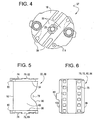
- the arc chute assembly 22 for a circuit breaker is shown.
- the arc chute assembly 22 includes a plurality of plates 68, a first side member 70 and a second side member 72.
- the plates 68 are metallic so as to induce magnetism thereby promoting removal of the arc generated by a short circuit trip in the circuit breaker.
- Each plate 68 has a protrusion 74 extending from each side thereof.
- Each plate 68 also includes a radiused notch 78 formed on one side thereof. The radiused notch 78 provides clearance for the contact arm 32 when the arc chute assembly 22 is mounted within the electrically insulative cassette half pieces 14, 60 ( Figures 2 and 3 ).
- first and second side members 70, 72 have a plurality of slots 76 formed therethrough.
- the protrusions 74 of the plates 68 are respectively inserted into a corresponding one of the slots 76 formed in the first and second side members 70, 72.
- the plates 68 are disposed in this manner between the first and second side members 70, 72 and are arranged in a stacked, spaced-apart relationship to each other.
- Second side member 72 is identical to first side member 70.
- the first and second side members 70, 72 are assembled so as to be opposedly oriented to each other.
- First side member 70 has a tab 80 centrally located on an end opposite to the radiused notch 78.
- a tab 80 is similarly located along second side member 72.
- a second arc chute assembly 20 comprises a plurality of plates 68 and third and fourth side members 82, 84.
- Third and fourth side members 82, 84 are identical to first and second side members 70, 72.
- Third and fourth side members 82, 84 are assembled so as to be opposedly oriented to each other.
- Third side member 82 has a tab 80 centrally located on an end opposite to the radiused notch 78 of the plate 68.
- a tab 80 is similarly located along the fourth side member 84.
- the first arc chute assembly 22 is correctly positioned into the first electrically insulative cassette half piece 14 by placing the tab 80 of the first side member 70 into the first recess 56 of first electrically insulative cassette half piece 14.
- the second arc chute assembly 20 is correctly positioned into the first electrically insulative cassette half piece 14 by placing tab 80 of the third side member 82 into the second recess 54 of first electrically insulative cassette half piece 14.
- a cassette assembly does not include tabs 80 and recesses 56, 54 to correctly position the arc chute assemblies 22, 20 for example, then the radiused notches 78 in the plates 68 might be incorrectly positioned to face opposite the first and second moveable contacts 30, 36 and the first and second fixed 28, 34 contacts. If this were to occur, the moveable contact arm 32 would not be permitted to rotate when the circuit breaker is tripped due to a short circuit event. Also, the arc chute assembly 22 could be placed upside down with respect to the first electrically insulative cassette half piece 14. If this were to occur, there can be insufficient air space between the plate 68 that is closest to the first moveable contact 30 and the line-side contact strap 16. The loss of a conducting plate in the arc chute assembly 22 can result in an insufficient amount of electromagnetic force to quench the, arc. Thus, tabs 80 ensure the correct positioning of the arc chute assemblies 22, 20 within the recesses 56, 54.
- the second electrically insulative cassette half piece 60 is placed over the first electrically insulative cassette half piece 14 to form a complete enclosure.
- tab 80 of the second side member 72 will be inserted into the third recess 64 of the second electrically insulative cassette half piece 60.
- Tab 80 of the fourth side member 84 will likewise be inserted into the fourth recess 66 of the second electrically insulative cassette half piece 60.
- the first and second arc chute assemblies 22, 20 will be correctly positioned into the first and second electrically insulative cassette half pieces 14, 60. Proper operation of the rotary contact arm assembly is achieved.
- the first, second, third and fourth side members 70, 72, 82, 84 have been heretofore described with tabs 80 that are centrally located.
- the advantage to this arrangement of the tabs 80 along the respective ends of the side members 70, 72, 82, 84 is the cost savings attributed to forming one mold pattern that can be used for all side members 70, 72, 82, 84 for both the first and second arc chute assemblies 22, 20.
- first and second arc chute assemblies 22, 20 are assembled prior to placement within the first electrically insulative cassette half piece 14, correct positioning of the first and second arc chute assemblies 22, 20 can also be achieved by using tabs 80 on only the first and third side members 70, 82.
- the second and fourth side members 72, 84 would have no tabs 80.
- tabs 80 on the first and third side members 70, 82 can be located generally offset as opposed to centrally located along the edges of the respective side members. However, this would further require the manufacture of a third type of side member to accommodate the offset tab arrangement.
- a cassette assembly for rotary contact circuit breakers utilizing a first electrically insulative cassette half piece 14 and a second electrically insulative cassette half piece 60 are arranged to mate with each other to form an enclosure.
- the electrically insulative cassette half pieces 14, 60 include improper installation rejection features for both the rotor 37 and the arc chute assemblies 22, 20. Therefore, the cassette assembly, as described herein, prevents such disassembly and reassembly that can be time consuming and increase the production cost of the circuit breaker.
Landscapes
- Breakers (AREA)
- Arc-Extinguishing Devices That Are Switches (AREA)
Claims (15)
- Kassettenanordnung, die zur Verwendung in einem Leitungsschutzschalter geeignet ist:eine erste elektrisch isolierende Kassettenhälfte (14) mit einer Innenoberfläche (52), wobei die Innenoberfläche (52) eine darin ausgebildete erste Aussparung (56) besitzt;eine zweite elektrisch isolierende Kassettenhälfte (60) mit einer Innenoberfläche (62), wobei die zweite elektrisch isolierende Kassettenhälfte (60) für eine Vereinigung mit der ersten elektrisch isolierenden Kassettenhälfte (14) eingerichtet ist; undeine erste Funkenlöschanordnung (22), die zwischen den ersten und zweiten elektrisch isolierenden Kassettenhälften (14, 60) angeordnet ist, wobei die erste Funkenlöschanordnung (22) enthält:ein erstes Seitenelement (70),ein zweites Seitenelement (72),eine Lasche (80), die sich aus dem ersten Seitenelement (70) heraus und durch die erste Aussparung (56) hindurch erstreckt, um das erste Seitenelement (70) in der ersten elektrisch isolierenden Kassettenhälfte (14) zu positionieren, um dadurch eine nicht korrekte Positionierung der ersten Funkenlöschanordnung (22) in Bezug auf die Kassettenanordnung zu verhindern, undmehrere Platten (68), die zwischen den ersten und zweiten Seitenelementen (70, 72) angeordnet und in einer gestaffelten Abstandsbeziehung eingerichtet sind, wobei jede Platte (68) eine Einkerbung (78) enthält, die auf einer Seite davon gegenüber dem Ende des Seitenelementes ausgebildet ist, auf welchem die Lasche (80) vorgesehen ist.
- Kassettenanordnung nach Anspruch 1, wobei die ersten und zweiten Seitenelemente (70, 72) mehrere dadurch hindurch ausgebildete Schlitze (76) enthalten, und jede von den mehreren Platten (68) jeweils einen Vorsprung (74) enthält, der sich aus jeder Seite davon erstreckt, wobei sich die Vorsprünge (74) durch die Schlitze (76) in den ersten und zweiten Seitenelementen (70, 72) hindurch erstrecken.
- Kassettenanordnung nach einem der vorstehenden Ansprüche, wobei das erste Seitenelement (70) ein oberes Ende und ein unteres Ende enthält, und einen Mittelpunkt, der sich entlang dem ersten Seitenelement (70) zwischen den oberen und unteren Enden befindet, und wobei sich die Lasche (80) an dem Mittelpunkt des ersten Seitenelementes (70) befindet.
- Kassettenanordnung nach einem der vorstehenden Ansprüche, wobei die Innenoberfläche (62) der zweiten elektrisch isolierenden Kassettenhälfte (60) eine darin ausgebildete dritte Aussparung (64) enthält und ferner eine Lasche (80) enthält, die sich aus dem zweiten Seitenelement (72) und durch die dritte Aussparung (64) hindurch erstreckt, um das zweite Seitenelement (72) in der zweiten elektrisch isolierenden Kassettenhälfte (60) zu positionieren.
- Kassettenanordnung nach einem der vorstehenden Ansprüche, wobei das zweite Seitenelement (72) ein oberes Ende und ein unteres Ende enthält, und einen Mittelpunkt, der sich entlang dem zweiten Seitenelement (72) zwischen den oberen und unteren Enden befindet, und wobei sich die Lasche (80) an dem Mittelpunkt des zweiten Seitenelementes (72) befindet.
- Kassettenanordnung nach einem der vorstehenden Ansprüche, die ferner eine zweite Funkenlöschanordnung (20) enthält, die zwischen den ersten und zweiten elektrisch isolierenden Kassettenhälften (14, 16) angeordnet ist, wobei die Innenoberfläche (52) der ersten elektrisch isolierenden Kassettenhälfte (14) eine darin ausgebildete zweite Aussparung (54) enthält, und wobei die zweite Funkenlöschanordnung (20) enthält:ein drittes Seitenelement (82);ein viertes Seitenelement (84);eine Lasche (80), die sich aus dem dritten Seitenelement (82) und durch die zweite Aussparung (54) hindurch erstreckt, um das dritte Seitenelement (82) in der ersten elektrisch isolierenden Kassettenhälfte (14) zu positionieren; undmehrere Platten (68), die zwischen den dritten und vierten Elementen (82, 84) angeordnet und in einer gestaffelten Abstandsbeziehung eingerichtet sind.
- Kassettenanordnung nach Anspruch 6, wobei die dritten und vierten Seitenelemente (82, 84) mehrere dadurch hindurch ausgebildete Schlitze (76) enthalten, und jede von den mehreren Platten (68) einen Vorsprung (74) enthält, der sich aus jeder Seite davon erstreckt, wobei sich die Vorsprünge (74) durch die Schlitze (76) in den dritten und vierten Seitenelementen (82, 84) hindurch erstrecken.
- Kassettenanordnung nach Anspruch 6 oder Anspruch 7, wobei das dritte Seitenelement (82) ein oberes Ende und ein unteres Ende enthält, und einen Mittelpunkt, der sich entlang dem dritten Seitenelement (82) zwischen den oberen und unteren Enden befindet, und wobei sich die Lasche (80) an dem Mittelpunkt des dritten Seitenelementes (82) befindet.
- Kassettenanordnung nach einem der Ansprüche 6 bis 8, wobei die Innenoberfläche (62) der zweiten elektrisch isolierenden Kassettenhälfte (60) eine darin ausgebildete vierte Aussparung (66) enthält und ferner eine Lasche (80) enthält, die sich aus dem vierten Seitenelement (84) und durch die vierte Aussparung (66) hindurch erstreckt, um das vierte Seitenelement (84) in der zweiten elektrisch isolierenden Kassettenhälfte (60) zu positionieren.
- Kassettenanordnung nach Anspruch 9, wobei das vierte Seitenelement (84) ein oberes Ende und ein unteres Ende enthält, und einen Mittelpunkt, der sich entlang dem vierten Seitenelement (84) zwischen den oberen und unteren Enden befindet, und wobei sich die Lasche (80) an dem Mittelpunkt des vierten Seitenelementes (84) befindet.
- Leitungsschutzschalteranordnung, aufweisend:eine Kassettenanordnung gemäß einem der vorstehenden Ansprüche;einen netzseitigen Kontaktstreifen (16), der zur Verbindung mit einem elektrischen Stromkreis eingerichtet ist, wobei der netzseitige Kontaktstreifen (16) einen ersten festen Kontakt (28) enthält, der mit dem netzseitigen Kontaktstreifen (16) verbunden ist, wobei sich die erste Funkenlöschanordnung (22) unmittelbar an dem netzseitigen Kontaktstreifen (16) zum Löschen von Lichtbögen befindet, die bei einem Überstromzustand auftreten;einen lastseitigen Kontaktstreifen (18), der zur Verbindung mit zugeordnetem elektrischen Gerät angeordnet ist, wobei der lastseitige Kontaktstreifen (18) einen zweiten festen Kontakt (34) enthält, der mit dem lastseitigen Kontaktstreifen (18) verbunden ist, wobei sich die zweite Funkenlöschanordnung (20) unmittelbar an dem lastseitigen Kontaktstreifen (18) zum Löschen von Lichtbögen befindet, die bei einem Überstromzustand auftreten;einen Rotor (37), der erste und zweite gegenüberliegende Seiten darauf definiert; undeinen beweglichen Kontaktarm (32) zwischen den ersten und zweiten Seiten, wobei der bewegliche Kontaktarm (32) einen ersten beweglichen Kontakt (30) an dem einen Ende definiert, das gegenüber dem ersten festen Kontakt (28) angeordnet ist, und einen zweiten beweglichen Kontakt (36) an einem dem einen Ende gegenüberliegenden Ende, und das unmittelbar an dem zweiten festen Kontakt (34) angeordnet ist, wobei der Rotor (37) und der bewegliche Kontaktarm (32) zwischen den ersten und zweiten elektrisch isolierenden Kassettenhälften (14, 16) festgehalten werden.
- Leitungsschutzschalteranordnung nach Anspruch 11, wobei das erste Seitenelement (70) ein oberes Ende und ein unteres Ende enthält, und einen entlang dem ersten Seitenelement (70) zwischen den oberen und unteren Enden angeordneten Mittelpunkt, und wobei sich die Lasche (80) an dem Mittelpunkt des ersten Seitenelementes (70) befindet, wobei das dritte Seitenelement (82) ein oberes Ende und ein unteres Ende enthält, und einen entlang dem dritten Seitenelement (82) zwischen den oberen und unteren Enden angeordneten Mittelpunkt, und wobei sich die Lasche (80) an dem Mittelpunkt des dritten Seitenelementes (82) befindet.
- Leitungsschutzschalteranordnung nach Anspruch 11, wobei das zweite Seitenelement (72) ein oberes Ende und ein unteres Ende enthält, und einen entlang dem zweiten Seitenelement (72) zwischen den oberen und unteren Enden angeordneten Mittelpunkt, und wobei sich die Lasche (80) an dem Mittelpunkt des ersten Seitenelementes (70) befindet, wobei das vierte Seitenelement (84) ein oberes Ende und ein unteres Ende enthält, und einen entlang dem vierten Seitenelement (84) zwischen den oberen und unteren Enden angeordneten Mittelpunkt, und wobei sich die Lasche (80) an dem Mittelpunkt des dritten Seitenelementes (82) befindet.
- Leitungsschutzschalter-Rotationskontaktanordnung, aufweisend:eine Kassettenanordnung gemäß einem der Ansprüche 1 bis 10;wobei die Innenoberfläche (52) der ersten elektrisch isolierenden Kassettenhälfte (14) eine Nut (58) besitzt;einen Rotor (37), der erste und zweite gegenüberliegende Seiten darauf definiert, wobei der Rotor (37) einen auf der ersten Seite ausgebildeten Stift (114) enthält, wobei sich der Stift (114) in der Nut (58) erstreckt, um ein Wandern des Rotors (37) in der Nut (58) zu ermöglichen;einen beweglichen Kontaktarm (32) zwischen den ersten und zweiten Seiten, wobei der bewegliche Kontaktarm (32) einen ersten beweglichen Kontakt (30) an einem Ende definiert, das gegenüber einem gegenüberliegenden ersten festen Kontakt (28) angeordnet ist, und einen zweiten beweglichen Kontakt (36) an einem dem einen Ende gegenüberliegenden Ende und das unmittelbar an dem zweiten festen Kontakt (34) angeordnet ist, wobei der Rotor (37) und der bewegliche Kontaktarm (32) zwischen den ersten und zweiten elektrisch isolierenden Gehäusehälften (14, 60) festhalten werden; undeinen Drehstift (25), der sich aus einem mittigen Abschnitt des beweglichen Kontaktarmes (32) zu einem mittigen Abschnitt des Rotors (37) erstreckt, um eine Drehung des beweglichen Kontaktarms (32) in Bezug auf den Rotor (37) zu ermöglichen.
- Leitungsschutzschalteranordnung, aufweisend:einen netzseitigen Kontaktstreifen (16), der zur Verbindung mit einem elektrischen Stromkreis angeordnet ist, wobei der netzseitige Kontaktstreifen (16) einen ersten festen Kontakt (28) enthält, der mit dem netzseitigen Kontaktstreifen (16) verbunden ist;einen lastseitigen Kontaktstreifen (18), der zur Verbindung mit zugeordnetem elektrischen Gerät angeordnet ist, wobei der lastseitige Kontaktstreifen (18) einen zweiten festen Kontakt (34) enthält, der mit dem lastseitigen Kontaktstreifen (18) verbunden ist; undeine Leitungsschutzschalter-Rotationskontaktanordnung (12), die zwischen den netz- und lastseitigen Kontaktstreifen (16, 18) angeordnet ist, wobei die Leitungsschutzschalter-Rotationskontaktanordnung (12) eine Kassettenanordnung gemäß einem der Ansprüche 1 bis 10 enthält;wobei die Innenoberfläche (52) der ersten elektrisch isolierenden Kassettenhälfte (14) eine Nut (58) besitzt;einen Rotor (37), der erste und zweite gegenüberliegende Seiten darauf definiert, wobei der Rotor (37) einen auf der ersten Seite ausgebildeten Stift (114) enthält, der sich in der Nut (58) erstreckt, um ein Wandern des Rotors (37) in der Nut (58) zu ermöglichen,einen beweglichen Kontaktarm (32) zwischen den ersten und zweiten Seiten, wobei der bewegliche Kontaktarm (32) einen ersten beweglichen Kontakt (30) an dem einem Ende definiert, das gegenüber dem gegenüberliegenden ersten festen Kontakt (28) angeordnet ist, und einen zweiten beweglichen Kontakt (36) an einem dem einen Ende gegenüberliegenden Ende und das unmittelbar an dem zweiten festen Kontakt (34) angeordnet ist, wobei der Rotor (37) und der bewegliche Kontaktarm (32) zwischen den ersten und zweiten elektrisch isolierenden Gehäusehälften (14, 60) festhalten werden; undeinen Drehstift (25), der sich aus einem mittigen Abschnitt des beweglichen Kontaktarmes (32) zu einem mittigen Abschnitt des Rotors (37) erstreckt, um eine Drehung des beweglichen Kontaktarms (32) in Bezug auf den Rotor (37) zu ermöglichen.
Applications Claiming Priority (3)
| Application Number | Priority Date | Filing Date | Title |
|---|---|---|---|
| US512980 | 1995-08-09 | ||
| US09/512,980 US6313425B1 (en) | 2000-02-24 | 2000-02-24 | Cassette assembly with rejection features |
| PCT/US2001/006053 WO2001063631A1 (en) | 2000-02-24 | 2001-02-26 | Cassette assembly with rejection features |
Publications (2)
| Publication Number | Publication Date |
|---|---|
| EP1175686A1 EP1175686A1 (de) | 2002-01-30 |
| EP1175686B1 true EP1175686B1 (de) | 2010-11-24 |
Family
ID=24041418
Family Applications (1)
| Application Number | Title | Priority Date | Filing Date |
|---|---|---|---|
| EP01916230A Expired - Lifetime EP1175686B1 (de) | 2000-02-24 | 2001-02-26 | Kassettenanordnung mit kodierungseigenschaften |
Country Status (5)
| Country | Link |
|---|---|
| US (2) | US6313425B1 (de) |
| EP (1) | EP1175686B1 (de) |
| CN (2) | CN100431079C (de) |
| PL (2) | PL197627B1 (de) |
| WO (1) | WO2001063631A1 (de) |
Families Citing this family (15)
| Publication number | Priority date | Publication date | Assignee | Title |
|---|---|---|---|---|
| FR2839195B1 (fr) * | 2002-04-29 | 2004-07-23 | Schneider Electric Ind Sa | Appareillage electrique de coupure comportant une chambre d'extinction d'arc munie d'ailettes de desionisation |
| US6930573B2 (en) * | 2003-08-29 | 2005-08-16 | General Electric Company | Interlocking cassettes for dimensional stability |
| US7297021B1 (en) * | 2006-08-31 | 2007-11-20 | Siemens Energy & Automation, Inc. | Devices, systems, and methods for bypassing an electrical meter |
| ITMI20072204A1 (it) * | 2007-11-21 | 2009-05-22 | Abb Spa | Dispositivo di interruzione uni-polare o multi-polare a doppia interruzione |
| ITMI20072202A1 (it) * | 2007-11-21 | 2009-05-22 | Abb Spa | Camera d'arco per un dispositivo di interruzione e dispositivo di interruzione comprendente tale camera d'arco. |
| US9953789B2 (en) * | 2009-09-18 | 2018-04-24 | Schneider Electric Industries Sas | Single-pole breaking unit comprising a rotary contact bridge, and a switchgear device, and circuit breaker comprising such a unit |
| US8350168B2 (en) | 2010-06-30 | 2013-01-08 | Schneider Electric USA, Inc. | Quad break modular circuit breaker interrupter |
| US8698024B2 (en) * | 2011-11-18 | 2014-04-15 | Schneider Electric USA, Inc. | Pressure sensitive trip mechanism with debris control |
| JP6200145B2 (ja) | 2011-11-30 | 2017-09-20 | ゼネラル・エレクトリック・カンパニイ | セラミック、そのセラミックを使用する傾斜抵抗率モノリス、および製造方法 |
| EP2650893A1 (de) * | 2012-04-12 | 2013-10-16 | ABB Oy | Elektrische Stromschaltungsvorrichtung |
| DE102012214826A1 (de) * | 2012-08-21 | 2014-02-27 | Siemens Aktiengesellschaft | Schaltvorrichtung |
| DE112016001197T5 (de) | 2015-03-13 | 2017-12-28 | General Electric Company | Trennschaltergehäuse und Verfahren zur Montage |
| DE102016216392A1 (de) * | 2016-08-31 | 2018-03-01 | Siemens Aktiengesellschaft | Schalteinheit für einen elektrischen Schalter und elektrischer Schalter |
| CN107482654B (zh) * | 2017-08-19 | 2020-09-22 | 国网山东省电力公司青州市供电公司 | 断路器及三相负荷调整装置 |
| IN202211071711A (de) * | 2022-12-12 | 2024-06-14 |
Family Cites Families (223)
| Publication number | Priority date | Publication date | Assignee | Title |
|---|---|---|---|---|
| US2244061A (en) * | 1940-07-31 | 1941-06-03 | Ite Circuit Breaker Ltd | Arc quencher |
| US2363606A (en) * | 1942-03-23 | 1944-11-28 | Square D Co | Arc suppressor |
| US2340682A (en) | 1942-05-06 | 1944-02-01 | Gen Electric | Electric contact element |
| US2551822A (en) * | 1947-12-30 | 1951-05-08 | Westinghouse Electric Corp | Circuit interrupter arc extinguisher |
| US2719203A (en) | 1952-05-02 | 1955-09-27 | Westinghouse Electric Corp | Circuit breakers |
| US2937254A (en) | 1957-02-05 | 1960-05-17 | Gen Electric | Panelboard unit |
| US3198915A (en) * | 1961-07-17 | 1965-08-03 | Ite Circuit Breaker Ltd | Interlocking construction for arc chute housing |
| US3162739A (en) | 1962-06-25 | 1964-12-22 | Gen Electric | Electric circuit breaker with improved trip means |
| US3158717A (en) | 1962-07-18 | 1964-11-24 | Gen Electric | Electric circuit breaker including stop means for limiting movement of a toggle linkage |
| US3197582A (en) | 1962-07-30 | 1965-07-27 | Fed Pacific Electric Co | Enclosed circuit interrupter |
| DE1227978B (de) | 1963-10-04 | 1966-11-03 | Licentia Gmbh | Elektrisches Schaltgeraet, insbesondere Schaltschuetz |
| US3307002A (en) | 1965-02-04 | 1967-02-28 | Texas Instruments Inc | Multipole circuit breaker |
| FR1585120A (de) | 1967-07-24 | 1970-01-09 | ||
| US3631369A (en) | 1970-04-27 | 1971-12-28 | Ite Imperial Corp | Blowoff means for circuit breaker latch |
| US3803455A (en) | 1973-01-02 | 1974-04-09 | Gen Electric | Electric circuit breaker static trip unit with thermal override |
| FR2241868B1 (de) | 1973-08-20 | 1976-06-18 | Merlin Gerin | |
| US3883781A (en) | 1973-09-06 | 1975-05-13 | Westinghouse Electric Corp | Remote controlled circuit interrupter |
| FR2360171A1 (fr) | 1976-07-30 | 1978-02-24 | Unelec | Mecanisme de commande de disjoncteur |
| FR2361737A1 (fr) | 1976-08-09 | 1978-03-10 | Unelec | Disjoncteur avec dispositif de verrouillage de la poignee de commande en cas de soudure des contacts |
| US4158119A (en) | 1977-07-20 | 1979-06-12 | Gould Inc. | Means for breaking welds formed between circuit breaker contacts |
| US4144513A (en) | 1977-08-18 | 1979-03-13 | Gould Inc. | Anti-rebound latch for current limiting switches |
| FR2410353A1 (fr) | 1977-11-28 | 1979-06-22 | Merlin Gerin | Relais polarise de declenchement d'un disjoncteur differentiel |
| US4166988A (en) | 1978-04-19 | 1979-09-04 | General Electric Company | Compact three-pole circuit breaker |
| FR2429487A1 (fr) | 1978-06-23 | 1980-01-18 | Merlin Gerin | Disjoncteur a bloc declencheur amovible |
| US4259651A (en) | 1978-10-16 | 1981-03-31 | Westinghouse Electric Corp. | Current limiting circuit interrupter with improved operating mechanism |
| US4220934A (en) | 1978-10-16 | 1980-09-02 | Westinghouse Electric Corp. | Current limiting circuit breaker with integral magnetic drive device housing and contact arm stop |
| US4255732A (en) | 1978-10-16 | 1981-03-10 | Westinghouse Electric Corp. | Current limiting circuit breaker |
| FR2452175A1 (fr) | 1979-03-23 | 1980-10-17 | Alsthom Unelec Sa | Appareil electrique de coupure dans l'air muni d'un dispositif indicateur de court-circuit |
| US4263492A (en) | 1979-09-21 | 1981-04-21 | Westinghouse Electric Corp. | Circuit breaker with anti-bounce mechanism |
| US4297663A (en) | 1979-10-26 | 1981-10-27 | General Electric Company | Circuit breaker accessories packaged in a standardized molded case |
| IT1129691B (it) | 1980-01-31 | 1986-06-11 | Elettromeccanica Spa Cge Comp | Complesso di estinzione rapida dell'arco elettrico in dispositivi di interruzione come interruttori elettrici |
| FR2478368A1 (fr) | 1980-03-12 | 1981-09-18 | Merlin Gerin | Mecanisme de manoeuvre pour disjoncteur tetrapolaire |
| JPS613106Y2 (de) | 1980-04-10 | 1986-01-31 | ||
| US4301342A (en) | 1980-06-23 | 1981-11-17 | General Electric Company | Circuit breaker condition indicator apparatus |
| DE8023509U1 (de) | 1980-08-29 | 1980-11-27 | Siemens Ag, 1000 Berlin Und 8000 Muenchen | Niederspannungs-Schutzschalter für Sperrhebel |
| DE3033213C2 (de) | 1980-08-29 | 1982-10-21 | Siemens AG, 1000 Berlin und 8000 München | Niederspannungs-Schutzschalter mit einem Sperrhebel |
| DE3034790A1 (de) | 1980-09-15 | 1982-03-25 | Siemens AG, 1000 Berlin und 8000 München | Leitungsschutzschalter |
| US4541032A (en) | 1980-10-21 | 1985-09-10 | B/K Patent Development Company, Inc. | Modular electrical shunts for integrated circuit applications |
| JPS57102281U (de) | 1980-12-16 | 1982-06-23 | ||
| DE3047360C2 (de) | 1980-12-16 | 1987-08-20 | Karl Pfisterer Elektrotechnische Spezialartikel Gmbh & Co Kg, 7000 Stuttgart | Schaltleiste |
| DE3110960A1 (de) | 1981-03-20 | 1982-09-30 | Basf Ag, 6700 Ludwigshafen | Elektrophotographisches aufzeichnungsmaterial |
| US4360852A (en) | 1981-04-01 | 1982-11-23 | Allis-Chalmers Corporation | Overcurrent and overtemperature protective circuit for power transistor system |
| US4409573A (en) | 1981-04-23 | 1983-10-11 | Siemens-Allis, Inc. | Electromagnetically actuated anti-rebound latch |
| FR2505553A1 (fr) | 1981-05-07 | 1982-11-12 | Merlin Gerin | Disjoncteur multipolaire a bloc declencheur magnetothermique interchangeable |
| FR2506066A1 (fr) | 1981-05-18 | 1982-11-19 | Merlin Gerin | Mecanisme de manoeuvre d'un disjoncteur electrique multipolaire a basse tension |
| FR2512582A1 (fr) | 1981-09-10 | 1983-03-11 | Merlin Gerin | Dispositif d'inviolabilite d'un disjoncteur differentiel |
| FR2514195A1 (fr) | 1981-10-05 | 1983-04-08 | Merlin Gerin | Disjoncteur multipolaire a bloc declencheur amovible |
| US4435690A (en) | 1982-04-26 | 1984-03-06 | Rte Corporation | Primary circuit breaker |
| US4658322A (en) | 1982-04-29 | 1987-04-14 | The United States Of America As Represented By The Secretary Of The Navy | Arcing fault detector |
| US4470027A (en) | 1982-07-16 | 1984-09-04 | Eaton Corporation | Molded case circuit breaker with improved high fault current interruption capability |
| IT8223118V0 (it) | 1982-10-07 | 1982-10-07 | Sace Spa | Interruttore elettrico con arresto della corsa della leva di comando in caso di saldatura dei contatti. |
| US4492941A (en) | 1983-02-18 | 1985-01-08 | Heinemann Electric Company | Circuit breaker comprising parallel connected sections |
| US4488133A (en) | 1983-03-28 | 1984-12-11 | Siemens-Allis, Inc. | Contact assembly including spring loaded cam follower overcenter means |
| FR2547122B1 (fr) | 1983-06-03 | 1985-07-05 | Merlin Gerin | Declencheur electronique selectif associe a un disjoncteur limiteur |
| JPS6068524A (ja) | 1983-09-21 | 1985-04-19 | 三菱電機株式会社 | 回路しや断器 |
| FR2553929B1 (fr) | 1983-10-21 | 1986-08-01 | Merlin Gerin | Mecanisme de commande d'un disjoncteur multipolaire basse tension |
| FR2553943B1 (fr) | 1983-10-24 | 1986-04-11 | Merlin Gerin | Dispositif differentiel residuel equipe d'un dispositif de surveillance de la source d'alimentation de l'electronique |
| DE3347120A1 (de) | 1983-12-22 | 1985-07-11 | Siemens AG, 1000 Berlin und 8000 München | Elektro-dynamisch oeffnendes kontaktsystem |
| US4595312A (en) | 1984-02-06 | 1986-06-17 | Corless Murray B | Pneumatically restorable retractable pavement marker and method of fabricating same |
| IT1173269B (it) | 1984-02-15 | 1987-06-18 | Cge Comp Gen Elettromecc | Combinazione di concegno di aggancio e di dispositivo sganciatore per evitare la richiusura dei contatti di un interuttori automatico dopo un'apertura dovuta a corto circuito |
| US4550360A (en) | 1984-05-21 | 1985-10-29 | General Electric Company | Circuit breaker static trip unit having automatic circuit trimming |
| US4672501A (en) | 1984-06-29 | 1987-06-09 | General Electric Company | Circuit breaker and protective relay unit |
| US4589052A (en) | 1984-07-17 | 1986-05-13 | General Electric Company | Digital I2 T pickup, time bands and timing control circuits for static trip circuit breakers |
| JPS6132324A (ja) | 1984-07-20 | 1986-02-15 | 富士電機株式会社 | 配線用遮断器の内部付属装置取付構造 |
| IT1175633B (it) | 1984-08-14 | 1987-07-15 | Cge Spa | Struttura di contatti di interruttore a limitazione di corrente manovabile sia manualmente che mediante azionatore elettromagnetico |
| DE3431288A1 (de) | 1984-08-23 | 1986-03-06 | Siemens AG, 1000 Berlin und 8000 München | Kontaktanordnung fuer niederspannungs-leistungsschalter mit einem zweiarmigen kontakthebel |
| US4631625A (en) | 1984-09-27 | 1986-12-23 | Siemens Energy & Automation, Inc. | Microprocessor controlled circuit breaker trip unit |
| US4612430A (en) | 1984-12-21 | 1986-09-16 | Square D Company | Anti-rebound latch |
| FR2578112B1 (fr) | 1985-02-25 | 1988-03-18 | Merlin Gerin | Disjoncteur a declencheur statique a chaine de traitement numerique shunte par une chaine de traitement analogique |
| FR2578090B1 (fr) | 1985-02-25 | 1989-12-01 | Merlin Gerin | Disjoncteur a declencheur statique numerise a fonction de declenchement a temps inverse |
| FR2578092B1 (fr) | 1985-02-25 | 1987-03-06 | Merlin Gerin | Disjoncteur a declencheur statique a echantillonnage et blocage a la derniere crete du signal |
| FR2578091B1 (fr) | 1985-02-25 | 1988-08-05 | Merlin Gerin | Disjoncteur a declencheur statique numerique dote d'un circuit de calibrage |
| FR2578113B1 (fr) | 1985-02-25 | 1988-04-15 | Merlin Gerin | Declencheur statique numerique a fonctions optionnelles pour un disjoncteur electrique |
| FR2578093B1 (fr) | 1985-02-27 | 1987-03-06 | Merlin Gerin | Disjoncteur differentiel unipolaire et neutre |
| US4642431A (en) | 1985-07-18 | 1987-02-10 | Westinghouse Electric Corp. | Molded case circuit breaker with a movable electrical contact positioned by a camming spring loaded clip |
| FR2589627B1 (fr) | 1985-10-31 | 1988-08-26 | Merlin Gerin | Mecanisme de commande pour disjoncteur electrique a basse tension |
| DE3679291D1 (de) | 1985-10-31 | 1991-06-20 | Merlin Gerin | Kinematische uebertragungskette zwischen dem steuermechanismus und den polen eines elektrischen lastschalters mit einem gespritzten isoliergehaeuse. |
| EP0235479B1 (de) | 1986-01-10 | 1993-08-04 | Merlin Gerin | Statischer Auslöser mit Testschaltung für elektrischen Leistungsschalter |
| FR2592998B1 (fr) | 1986-01-10 | 1988-03-18 | Merlin Gerin | Circuit test pour un declencheur electronique d'un disjoncteur differentiel. |
| ES2020284B3 (es) | 1986-02-28 | 1991-08-01 | Merlin Gerin | Aparato de corte de corriente con conmutador estatico y disyuntor de proteccion. |
| FR2596576B1 (fr) | 1986-03-26 | 1988-05-27 | Merlin Gerin | Disjoncteur electrique a autosoufflage a tenue dielectrique amelioree |
| FR2598266B1 (fr) | 1986-04-30 | 1994-02-18 | Merlin Et Gerin | Declencheur statique instantane pour un disjoncteur limiteur |
| FR2602610B1 (fr) | 1986-08-08 | 1994-05-20 | Merlin Et Gerin | Declencheur statique d'un disjoncteur electrique a indicateur d'usure des contacts |
| FR2604294B1 (fr) | 1986-09-23 | 1994-05-20 | Merlin Et Gerin | Disjoncteur differentiel multipolaire a assemblage modulaire |
| FR2604295B1 (fr) | 1986-09-23 | 1988-12-02 | Merlin Gerin | Appareil electrique de protection differentielle a circuit test |
| US4675481A (en) | 1986-10-09 | 1987-06-23 | General Electric Company | Compact electric safety switch |
| US4733211A (en) | 1987-01-13 | 1988-03-22 | General Electric Company | Molded case circuit breaker crossbar assembly |
| FR2612347B1 (fr) | 1987-03-09 | 1989-05-26 | Merlin Gerin | Declencheur statique comportant un circuit de detection d'un courant homopolaire |
| GB8705885D0 (en) | 1987-03-12 | 1987-04-15 | Y S Securities Ltd | Electrical switchgear |
| EP0313106B1 (de) | 1987-03-12 | 1992-12-16 | Merlin Gerin Limited | Elektrische Schaltanlage |
| FR2615323B1 (fr) | 1987-05-11 | 1989-06-30 | Merlin Gerin | Disjoncteur modulaire a bloc declencheur auxiliaire associe a un bloc disjoncteur multipolaire |
| FR2615322B1 (fr) | 1987-05-11 | 1989-06-30 | Merlin Gerin | Barre de declenchement d'un bloc disjoncteur multipolaire associe a un bloc declencheur auxiliaire |
| FR2616583B1 (fr) | 1987-06-09 | 1995-01-06 | Merlin Gerin | Mecanisme de commande d'un disjoncteur electrique miniature |
| GB8713791D0 (en) | 1987-06-12 | 1987-07-15 | Bicc Plc | Electric circuit breaking apparatus |
| FR2616957A1 (fr) | 1987-06-18 | 1988-12-23 | Merlin Gerin | Chambre d'extinction d'arc a pression elevee |
| FR2617633B1 (fr) | 1987-07-02 | 1989-11-17 | Merlin Gerin | Disjoncteur a arc tournant et a expansion |
| FR2621170A1 (fr) | 1987-09-25 | 1989-03-31 | Merlin Gerin | Disjoncteur-limiteur |
| DE3852455T2 (de) | 1987-10-01 | 1996-04-18 | Cge-Compagnia Generale Elettromeccanica S.P.A., Mailand/Milano | Hand- und elektromagnetisch betätigbare Kontaktanordnung für strombegrenzende Schalter. |
| FR2621748B1 (fr) | 1987-10-09 | 1996-07-05 | Merlin Gerin | Declencheur statique d'un disjoncteur a boitier moule |
| FR2622347B1 (fr) | 1987-10-26 | 1995-04-14 | Merlin Gerin | Dispositif de coupure pour un disjoncteur multipolaire a contact rotatif double |
| FR2622737B1 (fr) | 1987-11-04 | 1995-04-14 | Merlin Gerin | Disjoncteur electrique a auto-expansion a volume de chambre d'extinction variable |
| FR2624650B1 (fr) | 1987-12-10 | 1990-04-06 | Merlin Gerin | Disjoncteur multipolaire a boitier moule de calibre eleve |
| FR2624649B1 (fr) | 1987-12-10 | 1990-04-06 | Merlin Gerin | Disjoncteur multipolaire de calibre eleve constitue par deux boitiers accoles |
| FR2624666B1 (de) | 1987-12-10 | 1990-04-06 | Merlin Gerin | |
| US4831221A (en) | 1987-12-16 | 1989-05-16 | General Electric Company | Molded case circuit breaker auxiliary switch unit |
| DE3802184A1 (de) | 1988-01-26 | 1989-08-03 | Licentia Gmbh | Niederspannungsschalter mit sperrlaschen |
| FR2626724B1 (fr) | 1988-01-28 | 1993-02-12 | Merlin Gerin | Declencheur statique comportant un circuit de declenchement instantane independant de la tension d'alimentation |
| FR2626713B1 (fr) | 1988-01-28 | 1990-06-01 | Merlin Gerin | Declencheur electromagnetique a reglage du seuil de declenchement |
| FR2628259A1 (fr) | 1988-03-01 | 1989-09-08 | Merlin Gerin | Disjoncteur electrique a autosoufflage par pistonnage ou expansion de gaz isolant |
| FR2628262B1 (fr) | 1988-03-04 | 1995-05-12 | Merlin Gerin | Mecanisme de commande d'un bloc auxiliaire de declenchement pour disjoncteur modulaire |
| FR2630256B1 (fr) | 1988-04-14 | 1995-06-23 | Merlin Gerin | Declencheur electromagnetique a haute sensibilite |
| FR2631485B1 (fr) | 1988-05-13 | 1995-06-02 | Merlin Gerin | Mecanisme de commande de disjoncteur miniature a indicateur de soudure des contacts |
| FR2632771B1 (fr) | 1988-06-10 | 1990-08-31 | Merlin Gerin | Disjoncteur limiteur basse tension a chambre de coupure etanche |
| IT213976Z2 (it) | 1988-06-23 | 1990-03-05 | Cge Spa | Struttura di contatti elettrici nella quale la forza assiale di azionamento e' solo una piccola frazione della forza esercitata sui contatti. |
| US4870531A (en) | 1988-08-15 | 1989-09-26 | General Electric Company | Circuit breaker with removable display and keypad |
| FR2638909B1 (fr) | 1988-11-04 | 1995-03-31 | Merlin Gerin | Declencheur differentiel a circuit test et a telecommande d'ouverture autoprotegee |
| FR2639148B1 (fr) | 1988-11-16 | 1991-08-02 | Merlin Gerin | Declencheur magnetique a large plage de reglage du seuil de declenchement |
| FR2639760B1 (fr) | 1988-11-28 | 1996-02-09 | Merlin Gerin | Disjoncte ur modulaire equipe d'un bloc auxiliaire de declenchement a rearmement independant ou automatique |
| FR2640422B1 (fr) | 1988-12-14 | 1996-04-05 | Merlin Gerin | Dispositif d'assemblage modulaire d'un disjoncteur differentiel multipolaire |
| DE3843277A1 (de) | 1988-12-22 | 1990-06-28 | Bosch Gmbh Robert | Leistungsendstufe fuer elektromagnetische verbraucher |
| FR2641898B1 (fr) | 1989-01-17 | 1991-03-15 | Merlin Gerin | Disjoncteur electrique a autosoufflage |
| US4884164A (en) | 1989-02-01 | 1989-11-28 | General Electric Company | Molded case electronic circuit interrupter |
| US4975553A (en) * | 1989-02-22 | 1990-12-04 | Square D Company | Line terminal and arc stack for a circuit breaker |
| EP0385886B1 (de) | 1989-02-27 | 1994-11-09 | Merlin Gerin | Lastschalter mit rotierendem Lichtbogen und mit Zentrifugal-Effekt des Löschgases |
| FR2644624B1 (fr) | 1989-03-17 | 1996-03-22 | Merlin Gerin | Disjoncteur electrique a autoexpansion et a gaz isolant |
| US5004878A (en) | 1989-03-30 | 1991-04-02 | General Electric Company | Molded case circuit breaker movable contact arm arrangement |
| US5200724A (en) | 1989-03-30 | 1993-04-06 | Westinghouse Electric Corp. | Electrical circuit breaker operating handle block |
| US4951019A (en) | 1989-03-30 | 1990-08-21 | Westinghouse Electric Corp. | Electrical circuit breaker operating handle block |
| FR2646282B1 (fr) | 1989-04-20 | 1996-03-22 | Merlin Gerin | Commutateur auxiliaire a test manuel pour disjoncteur modulaire |
| GB2233155A (en) | 1989-04-27 | 1991-01-02 | Delta Circuits Protection | Electric circuit breaker |
| SE461557B (sv) | 1989-04-28 | 1990-02-26 | Asea Brown Boveri | Kontaktanordning foer elkkopplare |
| FR2646738B1 (fr) | 1989-05-03 | 1991-07-05 | Merlin Gerin | Declencheur statique pour un disjoncteur de protection d'un reseau triphase, permettant la detection du type de defaut |
| IT1230203B (it) | 1989-05-25 | 1991-10-18 | Bassani Spa | Interruttore automatico di protezione magnetotermica ad elevato potere di interruzione. |
| FR2648952B1 (fr) | 1989-06-26 | 1991-09-13 | Merlin Gerin | Disjoncteur limiteur equipe d'un dispositif retardateur de retombee de contact a effet electromagnetique |
| FR2649259B1 (fr) | 1989-07-03 | 1991-09-13 | Merlin Gerin | Declencheur statique comportant un systeme de desensibilisation de la protection terre |
| US4943888A (en) | 1989-07-10 | 1990-07-24 | General Electric Company | Electronic circuit breaker using digital circuitry having instantaneous trip capability |
| FR2650434B1 (fr) | 1989-07-26 | 1995-11-24 | Merlin Gerin | Disjoncteur basse tension a contacts multiples et a fortes intensites |
| DE8909831U1 (de) | 1989-08-16 | 1990-12-20 | Siemens AG, 80333 München | Hilfsschalteraufsatzblock |
| FR2651915B1 (fr) | 1989-09-13 | 1991-11-08 | Merlin Gerin | Disjoncteur statique ultra-rapide a isolement galvanique. |
| FR2651919B1 (fr) | 1989-09-13 | 1995-12-15 | Merlin Gerin | Disjoncteur comportant un declencheur electronique. |
| FR2655766B1 (fr) | 1989-12-11 | 1993-09-03 | Merlin Gerin | Disjoncteur hybride moyenne tension. |
| FR2659177B1 (fr) | 1990-03-01 | 1992-09-04 | Merlin Gerin | Capteur de courant pour un declencheur electronique d'un disjoncteur electrique. |
| FR2660794B1 (fr) | 1990-04-09 | 1996-07-26 | Merlin Gerin | Mecanisme de commande d'un disjoncteur electrique. |
| FR2661776B1 (fr) | 1990-05-04 | 1996-05-10 | Merlin Gerin | Declencheur instantane d'un disjoncteur. |
| IT219700Z2 (it) | 1990-05-29 | 1993-04-26 | Cge Spa | Dispositivo di fissaggio ad innesto con bloccaggio a scatto per unita'di comando e/o segnalazione |
| FR2663175A1 (fr) | 1990-06-12 | 1991-12-13 | Merlin Gerin | Commutateur statique. |
| FR2663457B1 (fr) | 1990-06-14 | 1996-06-07 | Merlin Gerin | Disjoncteur electrique a autoexpansion et a rotation de l'arc. |
| FR2663780B1 (fr) | 1990-06-26 | 1992-09-11 | Merlin Gerin | Disjoncteur haute tension a isolement gazeux et a mecanisme de commande pneumatique. |
| FR2665571B1 (fr) | 1990-08-01 | 1992-10-16 | Merlin Gerin | Disjoncteur electrique a arc tournant et a autoexpansion. |
| US5120921A (en) | 1990-09-27 | 1992-06-09 | Siemens Energy & Automation, Inc. | Circuit breaker including improved handle indication of contact position |
| FR2671228B1 (fr) | 1990-12-26 | 1996-07-26 | Merlin Gerin | Disjoncteur comportant une carte d'interface avec un declencheur. |
| US5262744A (en) | 1991-01-22 | 1993-11-16 | General Electric Company | Molded case circuit breaker multi-pole crossbar assembly |
| US5140115A (en) | 1991-02-25 | 1992-08-18 | General Electric Company | Circuit breaker contacts condition indicator |
| FR2674986B1 (fr) * | 1991-04-08 | 1996-03-08 | Hager Electro | Disjoncteur unipolaire modulaire perfectionne et son procede de montage. |
| US5184717A (en) | 1991-05-29 | 1993-02-09 | Westinghouse Electric Corp. | Circuit breaker with welded contacts |
| FR2677168B1 (fr) | 1991-06-03 | 1994-06-17 | Merlin Gerin | Disjoncteur moyenne tension a energie de commande reduite. |
| FR2679039B1 (fr) | 1991-07-09 | 1993-11-26 | Merlin Gerin | Dispositif de distribution d'energie electrique avec controle d'isolement. |
| FR2682529B1 (fr) | 1991-10-10 | 1993-11-26 | Merlin Gerin | Disjoncteur a verrouillage selectif. |
| FR2682530B1 (fr) | 1991-10-15 | 1993-11-26 | Merlin Gerin | Gamme de disjoncteurs basse tension a boitier moule. |
| FR2682531B1 (fr) | 1991-10-15 | 1993-11-26 | Merlin Gerin | Disjoncteur multipolaire a blocs unipolaires. |
| FR2682807B1 (fr) | 1991-10-17 | 1997-01-24 | Merlin Gerin | Disjoncteur electrique a deux cartouches a vide en serie. |
| FR2682808B1 (fr) | 1991-10-17 | 1997-01-24 | Merlin Gerin | Disjoncteur hybride a bobine de soufflage axial. |
| US5341191A (en) | 1991-10-18 | 1994-08-23 | Eaton Corporation | Molded case current limiting circuit breaker |
| US5260533A (en) | 1991-10-18 | 1993-11-09 | Westinghouse Electric Corp. | Molded case current limiting circuit breaker |
| TW200593B (de) | 1991-10-24 | 1993-02-21 | Fuji Electric Co Ltd | |
| FR2683089B1 (fr) | 1991-10-29 | 1993-12-31 | Merlin Gerin | Mecanisme de manóoeuvre pour disjoncteur tetrapolaire. |
| FR2683675B1 (fr) | 1991-11-13 | 1993-12-31 | Merlin Gerin | Procede et dispositif de reglage d'un declencheur technique a bilame. |
| FR2683938B1 (fr) | 1991-11-20 | 1993-12-31 | Gec Alsthom Sa | Disjoncteur-auto sectionneur a hexafluorure de soufre et applications aux cellules et aux postes et sous-stations prefabriques. |
| FR2683940B1 (fr) | 1991-11-20 | 1993-12-31 | Gec Alsthom Sa | Disjoncteur a moyenne tension pour l'interieur ou l'exterieur. |
| US5172087A (en) | 1992-01-31 | 1992-12-15 | General Electric Company | Handle connector for multi-pole circuit breaker |
| FR2687249B1 (fr) | 1992-02-07 | 1994-04-01 | Merlin Gerin | Mecanisme de commande d'un disjoncteur a boitier moule. |
| FR2687250A1 (fr) | 1992-02-07 | 1993-08-13 | Merlin Gerin | Dispositif de coupure a contacts multiples. |
| FR2688626B1 (fr) | 1992-03-13 | 1994-05-06 | Merlin Gerin | Disjoncteur a boitier moule a pont de contacts freine en fin de course de repulsion. |
| FR2688625B1 (fr) * | 1992-03-13 | 1997-05-09 | Merlin Gerin | Contact d'un disjoncteur a boitier moule |
| FR2690563B1 (fr) | 1992-04-23 | 1997-05-09 | Merlin Gerin | Disjoncteur debrochable a boitier moule. |
| FR2690560B1 (fr) | 1992-04-23 | 1997-05-09 | Merlin Gerin | Dispositif d'interverrouillage mecanique de deux disjoncteurs a boitier moule. |
| US5247142A (en) * | 1992-05-22 | 1993-09-21 | Westinghouse Electric Corp. | Circuit interrupter ARC chute side walls coated with high temperature refractory material |
| US5198956A (en) | 1992-06-19 | 1993-03-30 | Square D Company | Overtemperature sensing and signaling circuit |
| FR2693027B1 (fr) | 1992-06-30 | 1997-04-04 | Merlin Gerin | Interrupteur ou disjoncteur a auto-expansion. |
| US5552755A (en) | 1992-09-11 | 1996-09-03 | Eaton Corporation | Circuit breaker with auxiliary switch actuated by cascaded actuating members |
| FR2696275B1 (fr) | 1992-09-28 | 1994-10-28 | Merlin Gerin | Disjoncteur à boîtier moulé à blocs déclencheurs interchangeables. |
| KR940007922A (ko) | 1992-09-28 | 1994-04-28 | 기타오카 다카시 | 회로차단기 |
| FR2696276B1 (fr) | 1992-09-29 | 1994-12-02 | Merlin Gerin | Disjoncteur à boîtier moulé à contacts auxiliaires. |
| FR2696866B1 (fr) | 1992-10-13 | 1994-12-02 | Merlin Gerin | Mécanisme d'actionnement d'un interrupteur à trois positions. |
| DE4234619C2 (de) | 1992-10-14 | 1994-09-22 | Kloeckner Moeller Gmbh | Mit Schützen zu kombinierendes Überlastrelais |
| US5504283A (en) | 1992-10-28 | 1996-04-02 | Brother Kogyo Kabushiki Kaisha | Key switch device |
| FR2697669B1 (fr) | 1992-10-29 | 1995-01-06 | Merlin Gerin | Disjoncteur à bloc de débrochage des circuits auxiliaires. |
| FR2697670B1 (fr) | 1992-11-04 | 1994-12-02 | Merlin Gerin | Relais constituant un actionneur mécanique pour déclencher un disjoncteur ou un interrupteur différentiel. |
| US5296664A (en) | 1992-11-16 | 1994-03-22 | Westinghouse Electric Corp. | Circuit breaker with positive off protection |
| FR2699324A1 (fr) | 1992-12-11 | 1994-06-17 | Gen Electric | Commutateur auxiliaire compact pour disjoncteur à boîtier moulé. |
| DE4334577C1 (de) | 1993-10-11 | 1995-03-30 | Kloeckner Moeller Gmbh | Kontaktsystem für eine Strombegrenzungseinheit |
| FR2701159B1 (fr) | 1993-02-03 | 1995-03-31 | Merlin Gerin | Dispositif de condamnation mécanique et électrique d'un bloc de télécommande pour disjoncteur modulaire. |
| ES2122201T3 (es) | 1993-02-16 | 1998-12-16 | Schneider Electric Sa | Dispositivo de mando rotativo de un disyuntor. |
| FR2701596B1 (fr) | 1993-02-16 | 1995-04-14 | Merlin Gerin | Disjoncteur télécommande à came de réarmement. |
| FR2701617B1 (fr) | 1993-02-16 | 1995-04-14 | Merlin Gerin | Disjoncteur à télécommande et à fonction de sectionnement. |
| DE9422029U1 (de) | 1993-03-17 | 1997-09-18 | Ellenberger & Poensgen GmbH, 90518 Altdorf | Mehrpoliger Schutzschalter |
| EP0617449B1 (de) | 1993-03-25 | 1997-10-22 | Schneider Electric Sa | Schaltgerät |
| FR2703507B1 (fr) | 1993-04-01 | 1995-06-02 | Merlin Gerin | Disjoncteur comportant un dispositif de calibration amovible. |
| FR2703824B1 (fr) | 1993-04-07 | 1995-05-12 | Merlin Gerin | Disjoncteur limiteur multipolaire à répulsion électrodynamique. |
| US5479143A (en) | 1993-04-07 | 1995-12-26 | Merlin Gerin | Multipole circuit breaker with modular assembly |
| FR2703823B1 (fr) | 1993-04-08 | 1995-05-12 | Merlin Gerin | Module déclencheur magnéto-thermique. |
| FR2704091B1 (fr) | 1993-04-16 | 1995-06-02 | Merlin Gerin | Dispositif de réglage du seuil de déclenchement d'un disjoncteur multipolaire. |
| FR2704090B1 (fr) | 1993-04-16 | 1995-06-23 | Merlin Gerin | Declencheur auxiliaire pour disjoncteur. |
| FR2704354B1 (fr) | 1993-04-20 | 1995-06-23 | Merlin Gerin | Mecanisme de commande d'un disjoncteur electrique modulaire. |
| DE9308495U1 (de) | 1993-06-07 | 1994-10-20 | Weber AG, Emmenbrücke | Ein- oder mehrpolige NH-Sicherung |
| FR2707792B1 (fr) | 1993-07-02 | 1995-09-01 | Telemecanique | Unité de commande et/ou de signalisation à bornes. |
| US5361052A (en) | 1993-07-02 | 1994-11-01 | General Electric Company | Industrial-rated circuit breaker having universal application |
| GB9313928D0 (en) | 1993-07-06 | 1993-08-18 | Fenner Co Ltd J H | Improvements in and relating to electromechanical relays |
| DE4337344B4 (de) | 1993-11-02 | 2005-08-25 | Moeller Gmbh | Strombegrenzendes Kontaktsystem für Leistungsschalter |
| FR2714771B1 (fr) | 1994-01-06 | 1996-02-02 | Merlin Gerin | Dispositif de protection différentielle d'un transformateur de puissance. |
| FR2715517B1 (fr) | 1994-01-26 | 1996-03-22 | Merlin Gerin | Bloc déclencheur différentiel. |
| DE9401785U1 (de) | 1994-02-03 | 1995-07-20 | Klöckner-Moeller GmbH, 53115 Bonn | Schaltschloß mit einem Sperrmechanismus |
| US5485343A (en) | 1994-02-22 | 1996-01-16 | General Electric Company | Digital circuit interrupter with battery back-up facility |
| US5424701A (en) | 1994-02-25 | 1995-06-13 | General Electric | Operating mechanism for high ampere-rated circuit breakers |
| DE4408234C1 (de) | 1994-03-11 | 1995-06-14 | Kloeckner Moeller Gmbh | Gehäuseaufbau mit Zusatzeinrichtungen für Leistungsschalter |
| US5589672A (en) * | 1994-06-14 | 1996-12-31 | Fuji Electric Co., Ltd. | Circuit breaker with arc quenching device and vent |
| USD367265S (en) | 1994-07-15 | 1996-02-20 | Mitsubishi Denki Kabushiki Kaisha | Circuit breaker for distribution |
| IT1274993B (it) | 1994-09-01 | 1997-07-29 | Abb Elettrocondutture Spa | Circuito elettronico di base per interruttori di tipo differenziale dipendenti dalla tensione di rete |
| US5585609A (en) | 1994-09-28 | 1996-12-17 | Siemens Energy & Automation, Inc. | Circuit breaker with movable main contact multi-force-level biasing element |
| US5519561A (en) | 1994-11-08 | 1996-05-21 | Eaton Corporation | Circuit breaker using bimetal of thermal-magnetic trip to sense current |
| US5534835A (en) | 1995-03-30 | 1996-07-09 | Siemens Energy & Automation, Inc. | Circuit breaker with molded cam surfaces |
| US5608367A (en) | 1995-11-30 | 1997-03-04 | Eaton Corporation | Molded case circuit breaker with interchangeable trip unit having bimetal assembly which registers with permanent heater transformer airgap |
| IT1292453B1 (it) | 1997-07-02 | 1999-02-08 | Aeg Niederspannungstech Gmbh | Gruppo rotante di contatti per interrutttori di alta portata |
-
2000
- 2000-02-24 US US09/512,980 patent/US6313425B1/en not_active Expired - Lifetime
- 2000-07-28 US US09/627,738 patent/US6239398B1/en not_active Expired - Lifetime
-
2001
- 2001-02-26 CN CNB018002994A patent/CN100431079C/zh not_active Expired - Fee Related
- 2001-02-26 PL PL351306A patent/PL197627B1/pl not_active IP Right Cessation
- 2001-02-26 PL PL383517A patent/PL199343B1/pl not_active IP Right Cessation
- 2001-02-26 WO PCT/US2001/006053 patent/WO2001063631A1/en not_active Ceased
- 2001-02-26 EP EP01916230A patent/EP1175686B1/de not_active Expired - Lifetime
- 2001-02-26 CN CN2008102123547A patent/CN101369501B/zh not_active Expired - Fee Related
Also Published As
| Publication number | Publication date |
|---|---|
| PL351306A1 (en) | 2003-04-07 |
| PL199343B1 (pl) | 2008-09-30 |
| CN100431079C (zh) | 2008-11-05 |
| EP1175686A1 (de) | 2002-01-30 |
| US6239398B1 (en) | 2001-05-29 |
| CN1363105A (zh) | 2002-08-07 |
| US20010040147A1 (en) | 2001-11-15 |
| CN101369501B (zh) | 2011-03-09 |
| CN101369501A (zh) | 2009-02-18 |
| PL197627B1 (pl) | 2008-04-30 |
| US6313425B1 (en) | 2001-11-06 |
| WO2001063631A1 (en) | 2001-08-30 |
Similar Documents
| Publication | Publication Date | Title |
|---|---|---|
| US6239398B1 (en) | Cassette assembly with rejection features | |
| US3134877A (en) | Panelboard switch unit | |
| CN100552856C (zh) | 用于断路器的接触器组件 | |
| US6005206A (en) | Electrical switching apparatus with improved contact arm carrier arrangement | |
| US5718328A (en) | Current limiting circuit breaker | |
| EP0244247B1 (de) | Schalter mit einstellbarer magnetischer Auslöseeinheit | |
| CN100442422C (zh) | 用于电路断路器的接触器组件 | |
| US6373357B1 (en) | Pressure sensitive trip mechanism for a rotary breaker | |
| US5223681A (en) | Current limiting circuit breaker with over-molded magnet and metal plates | |
| EP3364435B1 (de) | Schutzschalter für gleichstrom in einem formgehäuse | |
| EP0955653A2 (de) | Elektrisches Schaltgerät mit Lichtbogenlaufschiene integriert mit festen Lichtbogenkontakt | |
| US20090000933A1 (en) | Circuit breaker subassembly apparatus | |
| US5416291A (en) | Current limiting circuit breaker operating mechanism including linkage | |
| KR102026642B1 (ko) | 배선용 차단기 | |
| US5874699A (en) | Molded case circuit breaker and moving conductor assembly therefor | |
| US3202775A (en) | Rotor type electric switch with resiliently mounted contact members | |
| US20080088394A1 (en) | Electical switching apparatus, and movable contact assembly and contact spring assembly therefor | |
| US2922004A (en) | Electric circuit breaker | |
| US6930573B2 (en) | Interlocking cassettes for dimensional stability | |
| US20020117477A1 (en) | Modular arc chamber assembly | |
| US3005066A (en) | Circuit breaker | |
| US6281461B1 (en) | Circuit breaker rotor assembly having arc prevention structure | |
| JP2756481B2 (ja) | 回路遮断器 | |
| US9805895B2 (en) | Electrical switching apparatus and clinch joint assembly therefor | |
| WO2001071745A1 (en) | Vent screen with rejection features |
Legal Events
| Date | Code | Title | Description |
|---|---|---|---|
| PUAI | Public reference made under article 153(3) epc to a published international application that has entered the european phase |
Free format text: ORIGINAL CODE: 0009012 |
|
| AK | Designated contracting states |
Kind code of ref document: A1 Designated state(s): AT BE CH CY DE DK ES FI FR GB GR IE IT LI LU MC NL PT SE TR |
|
| 17P | Request for examination filed |
Effective date: 20020228 |
|
| RBV | Designated contracting states (corrected) |
Designated state(s): IT |
|
| REG | Reference to a national code |
Ref country code: DE Ref legal event code: 8566 |
|
| 17Q | First examination report despatched |
Effective date: 20061205 |
|
| GRAP | Despatch of communication of intention to grant a patent |
Free format text: ORIGINAL CODE: EPIDOSNIGR1 |
|
| GRAS | Grant fee paid |
Free format text: ORIGINAL CODE: EPIDOSNIGR3 |
|
| GRAA | (expected) grant |
Free format text: ORIGINAL CODE: 0009210 |
|
| AK | Designated contracting states |
Kind code of ref document: B1 Designated state(s): IT |
|
| PLBE | No opposition filed within time limit |
Free format text: ORIGINAL CODE: 0009261 |
|
| STAA | Information on the status of an ep patent application or granted ep patent |
Free format text: STATUS: NO OPPOSITION FILED WITHIN TIME LIMIT |
|
| 26N | No opposition filed |
Effective date: 20110825 |
|
| PGFP | Annual fee paid to national office [announced via postgrant information from national office to epo] |
Ref country code: IT Payment date: 20150225 Year of fee payment: 15 |
|
| PG25 | Lapsed in a contracting state [announced via postgrant information from national office to epo] |
Ref country code: IT Free format text: LAPSE BECAUSE OF NON-PAYMENT OF DUE FEES Effective date: 20160226 |