EP1175295B1 - Produits composites creux et procede de fabrication - Google Patents
Produits composites creux et procede de fabrication Download PDFInfo
- Publication number
- EP1175295B1 EP1175295B1 EP00925393A EP00925393A EP1175295B1 EP 1175295 B1 EP1175295 B1 EP 1175295B1 EP 00925393 A EP00925393 A EP 00925393A EP 00925393 A EP00925393 A EP 00925393A EP 1175295 B1 EP1175295 B1 EP 1175295B1
- Authority
- EP
- European Patent Office
- Prior art keywords
- composite
- composite structure
- process according
- product
- inflatable pocket
- Prior art date
- Legal status (The legal status is an assumption and is not a legal conclusion. Google has not performed a legal analysis and makes no representation as to the accuracy of the status listed.)
- Expired - Lifetime
Links
- 239000002131 composite material Substances 0.000 title claims abstract description 76
- 238000000034 method Methods 0.000 title claims abstract description 44
- 239000000463 material Substances 0.000 claims abstract description 36
- 239000011521 glass Substances 0.000 claims abstract description 10
- 238000004519 manufacturing process Methods 0.000 claims description 13
- 239000011368 organic material Substances 0.000 claims description 13
- 230000003014 reinforcing effect Effects 0.000 claims description 10
- 229920001169 thermoplastic Polymers 0.000 claims description 10
- 239000004416 thermosoftening plastic Substances 0.000 claims description 10
- 238000010438 heat treatment Methods 0.000 claims description 8
- 239000012779 reinforcing material Substances 0.000 claims description 7
- 229920001187 thermosetting polymer Polymers 0.000 claims description 2
- 238000007711 solidification Methods 0.000 claims 2
- 230000008023 solidification Effects 0.000 claims 2
- 238000005096 rolling process Methods 0.000 claims 1
- 239000000945 filler Substances 0.000 abstract 1
- 239000004744 fabric Substances 0.000 description 24
- 230000002787 reinforcement Effects 0.000 description 24
- 239000000835 fiber Substances 0.000 description 22
- 239000005416 organic matter Substances 0.000 description 17
- -1 polypropylene Polymers 0.000 description 14
- 238000007664 blowing Methods 0.000 description 11
- 238000000465 moulding Methods 0.000 description 11
- 239000012783 reinforcing fiber Substances 0.000 description 10
- 239000004743 Polypropylene Substances 0.000 description 9
- 229920001155 polypropylene Polymers 0.000 description 9
- IJGRMHOSHXDMSA-UHFFFAOYSA-N Atomic nitrogen Chemical compound N#N IJGRMHOSHXDMSA-UHFFFAOYSA-N 0.000 description 6
- 230000006835 compression Effects 0.000 description 6
- 238000007906 compression Methods 0.000 description 6
- 230000009969 flowable effect Effects 0.000 description 6
- 238000002844 melting Methods 0.000 description 4
- 230000008018 melting Effects 0.000 description 4
- 238000007596 consolidation process Methods 0.000 description 3
- 239000012530 fluid Substances 0.000 description 3
- 238000002347 injection Methods 0.000 description 3
- 239000007924 injection Substances 0.000 description 3
- 229910052757 nitrogen Inorganic materials 0.000 description 3
- 229920000642 polymer Polymers 0.000 description 3
- 238000004804 winding Methods 0.000 description 3
- 239000004952 Polyamide Substances 0.000 description 2
- 239000004698 Polyethylene Substances 0.000 description 2
- 239000006096 absorbing agent Substances 0.000 description 2
- 230000007613 environmental effect Effects 0.000 description 2
- 239000006260 foam Substances 0.000 description 2
- 239000007789 gas Substances 0.000 description 2
- 239000003365 glass fiber Substances 0.000 description 2
- 238000001746 injection moulding Methods 0.000 description 2
- 229920002647 polyamide Polymers 0.000 description 2
- 229920001707 polybutylene terephthalate Polymers 0.000 description 2
- 229920000573 polyethylene Polymers 0.000 description 2
- 238000007789 sealing Methods 0.000 description 2
- 229920006302 stretch film Polymers 0.000 description 2
- 229920000049 Carbon (fiber) Polymers 0.000 description 1
- 206010061218 Inflammation Diseases 0.000 description 1
- 229910000831 Steel Inorganic materials 0.000 description 1
- 239000004760 aramid Substances 0.000 description 1
- 229920006231 aramid fiber Polymers 0.000 description 1
- 238000005452 bending Methods 0.000 description 1
- 239000004917 carbon fiber Substances 0.000 description 1
- 230000001413 cellular effect Effects 0.000 description 1
- 230000000295 complement effect Effects 0.000 description 1
- 238000009826 distribution Methods 0.000 description 1
- 229920001971 elastomer Polymers 0.000 description 1
- 239000000806 elastomer Substances 0.000 description 1
- 230000004054 inflammatory process Effects 0.000 description 1
- 238000010102 injection blow moulding Methods 0.000 description 1
- 238000003780 insertion Methods 0.000 description 1
- 230000037431 insertion Effects 0.000 description 1
- 230000010354 integration Effects 0.000 description 1
- 239000004620 low density foam Substances 0.000 description 1
- 239000000155 melt Substances 0.000 description 1
- 239000012528 membrane Substances 0.000 description 1
- 239000000203 mixture Substances 0.000 description 1
- 230000003647 oxidation Effects 0.000 description 1
- 238000007254 oxidation reaction Methods 0.000 description 1
- 239000004033 plastic Substances 0.000 description 1
- 229920003023 plastic Polymers 0.000 description 1
- 238000007747 plating Methods 0.000 description 1
- 229920001296 polysiloxane Polymers 0.000 description 1
- 238000004321 preservation Methods 0.000 description 1
- 230000001681 protective effect Effects 0.000 description 1
- 238000010926 purge Methods 0.000 description 1
- 230000005855 radiation Effects 0.000 description 1
- 238000004064 recycling Methods 0.000 description 1
- 239000007787 solid Substances 0.000 description 1
- 239000007858 starting material Substances 0.000 description 1
- 239000010959 steel Substances 0.000 description 1
- 239000003351 stiffener Substances 0.000 description 1
- 239000012209 synthetic fiber Substances 0.000 description 1
- 229920002994 synthetic fiber Polymers 0.000 description 1
- 239000002759 woven fabric Substances 0.000 description 1
Images

Classifications
-
- B—PERFORMING OPERATIONS; TRANSPORTING
- B29—WORKING OF PLASTICS; WORKING OF SUBSTANCES IN A PLASTIC STATE IN GENERAL
- B29C—SHAPING OR JOINING OF PLASTICS; SHAPING OF MATERIAL IN A PLASTIC STATE, NOT OTHERWISE PROVIDED FOR; AFTER-TREATMENT OF THE SHAPED PRODUCTS, e.g. REPAIRING
- B29C49/00—Blow-moulding, i.e. blowing a preform or parison to a desired shape within a mould; Apparatus therefor
- B29C49/20—Blow-moulding, i.e. blowing a preform or parison to a desired shape within a mould; Apparatus therefor of articles having inserts or reinforcements ; Handling of inserts or reinforcements
-
- B—PERFORMING OPERATIONS; TRANSPORTING
- B29—WORKING OF PLASTICS; WORKING OF SUBSTANCES IN A PLASTIC STATE IN GENERAL
- B29C—SHAPING OR JOINING OF PLASTICS; SHAPING OF MATERIAL IN A PLASTIC STATE, NOT OTHERWISE PROVIDED FOR; AFTER-TREATMENT OF THE SHAPED PRODUCTS, e.g. REPAIRING
- B29C70/00—Shaping composites, i.e. plastics material comprising reinforcements, fillers or preformed parts, e.g. inserts
- B29C70/04—Shaping composites, i.e. plastics material comprising reinforcements, fillers or preformed parts, e.g. inserts comprising reinforcements only, e.g. self-reinforcing plastics
- B29C70/28—Shaping operations therefor
- B29C70/40—Shaping or impregnating by compression not applied
- B29C70/42—Shaping or impregnating by compression not applied for producing articles of definite length, i.e. discrete articles
- B29C70/44—Shaping or impregnating by compression not applied for producing articles of definite length, i.e. discrete articles using isostatic pressure, e.g. pressure difference-moulding, vacuum bag-moulding, autoclave-moulding or expanding rubber-moulding
- B29C70/446—Moulding structures having an axis of symmetry or at least one channel, e.g. tubular structures, frames
-
- B—PERFORMING OPERATIONS; TRANSPORTING
- B29—WORKING OF PLASTICS; WORKING OF SUBSTANCES IN A PLASTIC STATE IN GENERAL
- B29C—SHAPING OR JOINING OF PLASTICS; SHAPING OF MATERIAL IN A PLASTIC STATE, NOT OTHERWISE PROVIDED FOR; AFTER-TREATMENT OF THE SHAPED PRODUCTS, e.g. REPAIRING
- B29C2949/00—Indexing scheme relating to blow-moulding
- B29C2949/07—Preforms or parisons characterised by their configuration
- B29C2949/079—Auxiliary parts or inserts
- B29C2949/08—Preforms made of several individual parts, e.g. by welding or gluing parts together
-
- B—PERFORMING OPERATIONS; TRANSPORTING
- B29—WORKING OF PLASTICS; WORKING OF SUBSTANCES IN A PLASTIC STATE IN GENERAL
- B29C—SHAPING OR JOINING OF PLASTICS; SHAPING OF MATERIAL IN A PLASTIC STATE, NOT OTHERWISE PROVIDED FOR; AFTER-TREATMENT OF THE SHAPED PRODUCTS, e.g. REPAIRING
- B29C49/00—Blow-moulding, i.e. blowing a preform or parison to a desired shape within a mould; Apparatus therefor
- B29C49/02—Combined blow-moulding and manufacture of the preform or the parison
- B29C49/06905—Using combined techniques for making the preform
- B29C49/0691—Using combined techniques for making the preform using sheet like material, e.g. sheet blow-moulding from joined sheets
-
- B—PERFORMING OPERATIONS; TRANSPORTING
- B29—WORKING OF PLASTICS; WORKING OF SUBSTANCES IN A PLASTIC STATE IN GENERAL
- B29C—SHAPING OR JOINING OF PLASTICS; SHAPING OF MATERIAL IN A PLASTIC STATE, NOT OTHERWISE PROVIDED FOR; AFTER-TREATMENT OF THE SHAPED PRODUCTS, e.g. REPAIRING
- B29C49/00—Blow-moulding, i.e. blowing a preform or parison to a desired shape within a mould; Apparatus therefor
- B29C49/42—Component parts, details or accessories; Auxiliary operations
- B29C49/44—Component parts, details or accessories; Auxiliary operations for applying pressure through the walls of an inflated bag
-
- B—PERFORMING OPERATIONS; TRANSPORTING
- B29—WORKING OF PLASTICS; WORKING OF SUBSTANCES IN A PLASTIC STATE IN GENERAL
- B29K—INDEXING SCHEME ASSOCIATED WITH SUBCLASSES B29B, B29C OR B29D, RELATING TO MOULDING MATERIALS OR TO MATERIALS FOR MOULDS, REINFORCEMENTS, FILLERS OR PREFORMED PARTS, e.g. INSERTS
- B29K2105/00—Condition, form or state of moulded material or of the material to be shaped
- B29K2105/06—Condition, form or state of moulded material or of the material to be shaped containing reinforcements, fillers or inserts
- B29K2105/08—Condition, form or state of moulded material or of the material to be shaped containing reinforcements, fillers or inserts of continuous length, e.g. cords, rovings, mats, fabrics, strands or yarns
-
- B—PERFORMING OPERATIONS; TRANSPORTING
- B29—WORKING OF PLASTICS; WORKING OF SUBSTANCES IN A PLASTIC STATE IN GENERAL
- B29K—INDEXING SCHEME ASSOCIATED WITH SUBCLASSES B29B, B29C OR B29D, RELATING TO MOULDING MATERIALS OR TO MATERIALS FOR MOULDS, REINFORCEMENTS, FILLERS OR PREFORMED PARTS, e.g. INSERTS
- B29K2105/00—Condition, form or state of moulded material or of the material to be shaped
- B29K2105/25—Solid
- B29K2105/253—Preform
- B29K2105/258—Tubular
Definitions
- the present invention relates to new composite products as well as a manufacturing process for these products.
- product composite product comprising at least two materials of different melting points
- hollow product is meant that the product has, inside, one or more hollow parts surrounded by walls, the hollow part or parts inside the product may be empty or provided with one or more filling materials.
- Composite products are generally molded products solid, obtained by injection or compression in a mold or hurry. Depending on the materials used and the shape of these products, they can suit different types of applications.
- the present invention seeks to obtain new composite products particularly suited to use as structural and / or energy absorbing parts (for example as bumper beams of motor vehicles, protective rails, energy absorbers for bumpers, parts structure for boats, support sleepers, etc.).
- the present invention has also intended to provide a quick and economical process for manufacture of these products.
- this product being a hollow composite product comprising more 20% by weight of reinforcing material (preferably glass) in the form of long fibers, the thickness of the walls of the product (whether external walls or possibly the internal walls separating the case several hollow parts of the part) being further included between 1 and 10 mm approximately.
- reinforcing material preferably glass
- the present invention also relates to a manufacturing process of hollow composite products suitable for the manufacture of products according to the invention, this process being defined in claim 1.
- a preheated assembly comprising a core is introduced into a mold at least one inflatable pocket, this inflatable pocket being coated with at least one composite structure comprising at least one material of reinforcement in the form of long fibers and the preheated assembly comprising at least one material able to flow, and, in this process, the bag is inflated inflatable under a pressure higher than 40 bars so that the whole preheated takes the form of the mold.
- the process according to the present invention should be clearly distinguished already existing processes for manufacturing hollow products by blowing (e.g. injection molding and blow molding processes or processes in which a parison of material is extruded thermoplastic before placing in a mold and then blowing), these processes using blowing pressures below 15 bar and in most cases not exceeding 5 bars.
- blowing e.g. injection molding and blow molding processes or processes in which a parison of material is extruded thermoplastic before placing in a mold and then blowing
- blowing pressures below 15 bar and in most cases not exceeding 5 bars.
- different processing steps and different starting materials are not suitable for the manufacture of products composites as sought after according to the invention and / or are not economical (for example they use expensive balloons inflatable in silicone) and / or are only suitable for small series (10 to 15 pieces per day) and / or may possibly ask for some of them environmental issues.
- Hollow products with long reinforcing fibers are as for them generally obtained by molding in the presence of a inflatable balloon.
- a porous self-supporting preform which is introduced into a balloon formed of a flexible expandable membrane covered with a material comprising thermoplastic yarns and hybrid yarns of glass and a thermoplastic.
- the assembly thus formed is placed in a mold and then is heated by simultaneously inflating the balloon at a pressure of the order of 0.5 to 1 MPa (5 to 10 bars). Due to the low pressure implementation, this process remains limited to the manufacture of hollow products of little complex shape and relatively high thickness.
- the method according to the invention can be operated manually or automated. It is particularly simple and economical, meets a concern for safety and environmental preservation and allows pieces of more or less complex shape and of more or less dimensions less important. In particular, it is suitable for the manufacture of large parts or series of parts (unlike under molding processes vacuum or injection molding then blowing), this process can also be used to make small series of products.
- the process according to the invention is also fast, it makes it possible to obtain parts hollow composites in a single molding operation and allows consider the manufacture of parts with high reinforcement rates. In particular, it makes it possible to obtain parts cost-effectively reinforcements greater than 40 or 45% by weight approximately, these rates being able to go up to 75-80%.
- the hollow composite product obtained according to the invention has generally between 20 and 80% by weight of reinforcing material (from preferably glass), in particular at least 20% (by weight) of material reinforcement in the form of long fibers (this product may include. as reinforcements, only long fibers or may include reinforcements in other forms, for example in the form of fibers short, in addition to long fibers), and has a wall thickness between 1 and 10 mm approximately, preferably less than or equal to 6 mm. It also presents, in most cases and preferably, a closed section (for example circular or rectangular or trapezoidal or square ).
- This product has good strength characteristics mechanical for moderate weight, the couple weight / mechanical resistance (or inertia in the event of an impact) of this product being more advantageous than that of the same full product or as that of the same product with a open section (for example a product with a U section).
- the product according to the invention has in particular good resistance to torsion and to bending, while having a weight and a thickness of the walls particularly weak.
- the wall thickness of the product as defined is economically advantageous while obtaining the resistance characteristics sought and while allowing, for the product realization, the use of complex composite structures formed of several layers, as explained later.
- the hollow composite part (or product hollow composite) according to the invention can be provided with a material of filling, for example with a foam (filling is by example by injecting a cellular polymer in the form of inside the room), but is preferably empty so as to present a set of cost / weight / mechanical properties particularly advantageous.
- a material of filling for example with a foam (filling is by example by injecting a cellular polymer in the form of inside the room), but is preferably empty so as to present a set of cost / weight / mechanical properties particularly advantageous.
- the composite structure used in the process according to the invention is not very thick compared to its surface, is generally planar but can have, if necessary, sufficient flexibility to be able to be collected and stored in rolled form. It can be full or openwork and advantageously has sufficient hold (or a structure sufficiently fixed or tied or rigid) to be able to be manipulated and used in the process according to the invention. It can be made up of one or several layers, as explained later.
- the composite structure used according to the invention is formed of at least minus two materials with different melting points.
- it comprises at least one thermoplastic organic material (such as polypropylene, polyethylene, polybutylene terephthalate, polyethylene cerephthalate, polyamide, etc.) or thermosetting and less reinforcing material (at least partly in the form of fibers, for example natural, synthetic fibers, carbon fibers, aramid fibers, glass fibers ...) of this organic matter.
- thermoplastic organic material such as polypropylene, polyethylene, polybutylene terephthalate, polyethylene cerephthalate, polyamide, etc.
- thermosetting and less reinforcing material at least partly in the form of fibers, for example natural, synthetic fibers, carbon fibers, aramid fibers, glass fibers .
- it comprises at least one organic material thermoplastic and preferably also it comprises at least glass fibers.
- a structure is used composite comprising a reinforcing material in the form of fibers "Long", that is to say in the form of fibers having a length greater than 1 mm (as opposed to “short” fibers with a length between 0.1 and 1 mm).
- "long" fibers mentioned in the present invention are fibers having initially (in the composite structure ready for use in the method according to the invention) a length such as their final length (in the finished hollow product obtained after molding) is greater than 1 mm (their initial length then being a fortiori greater than 1 mm).
- the long fibers of the composite structure used are presented by example in the form of continuous fibers (several centimeters or meters in length) or "cut" fibers (longer than 1 mm, for example of the order of a few millimeters or centimeters, these so-called “cut” fibers also including verranne-type fibers).
- the level of long fibers in the composite structure is also advantageously chosen to be greater than 20% by weight of the structure.
- the presence of a reinforcing material in the form of long fibers is important to limit the risks of perforation and inflammation of the inflatable bag (these phenomena having been observed using only short reinforcing fibers) during molding and for obtaining good mechanical properties (especially when these are continuous wires).
- the presence of long reinforcing fibers in the structure, especially of continuous yarns, also contributes to the good behavior of the structure during its handling and setting works and makes possible the heating and winding of the structure, as required in several embodiments of the method according the invention.
- the reinforcement material (s) (or higher melting point) in the form of fibers are generally in the form of threads or filaments (the filaments being wires of very small diameter, for example of the order of 5 to 24 microns in diameter in the case of glass, these filaments being obtained for example by drawing threads of material fondue and being generally gathered in one or more wires of larger diameter).
- the composite structure can also advantageously comprise at least one organic material (or lowest melting point in the most general case) in the form of wires or filaments; in particular, it is advantageous that the composite structure includes at least one assembly or ply of wires comprising filaments or threads of organic material intermingled and / or interposed with reinforcing filaments or threads.
- the composite structure can in particular advantageously include mixed threads obtained by the meeting and the simultaneous winding of threads or filaments of one of the materials and of threads or filaments of the other material, these mixed threads can be mixed in the structure with threads of one of the materials and / or with threads of the other matter.
- the composite structure comprises at least one assembly or a layer of yarn formed by at least 50% (preferably at least 80% and particularly preferably 100%) by weight of mixed yarns.
- these mixed threads are so-called “co-blended” threads (or “threads composites ”), ie yarns composed of filaments of one of the materials and filaments of the other material, the filaments being mixed within the threads, this mode being all the more advantageous as the mixture is homogeneous), these wires being generally obtained by assembling filaments directly during their manufacture (according to the methods described for example in patent applications EP-A-0 590 695 and EP-A-0 616 055).
- the co-mixed threads consist of glass filaments and intimately thermoplastic organic material filaments mixed.
- the composite structure has advantageously sufficient holding to be able to be handled and implementation in the method according to the invention.
- it must be easily deformable to conform to the shape of the mold.
- the layer (s) or parts of the structure including the long reinforcing fibers must be easily deformable.
- the layer (s) or parts of the structure including the long reinforcing fibers may be in the form of mats (of continuous or cut threads) or loosely packed fabrics (i.e. fabrics with deformable weave, for example knitwear or "jersey” type fabrics or twill weave fabrics).
- the composite structure comprises at least one network of intertwined wires, more particularly comprises an assembly or a web of wires or reinforcing filaments in the form of a fabric (or knitted fabric), the use of fabric (s) used in particular to obtain composite products having good mechanical properties.
- the same sons or sets of threads can be used to form the warp and weft fabric or network, where the weft and the warp can be made of different sons or different associations of sons.
- the wire network can be, for example, in the form of a fabric whose chain is consisting of threads mixed organic matter / reinforcing material and the weft of which consists of 80 to 100% organic material yarn same nature as that of co-mixed threads.
- This network presents a preferential direction of orientation of the reinforcing wires (structure unidirectional).
- the structure comprises at least one fabric (advantageously deformable, by example a jersey knit) comprising threads mixed in chain and frame.
- the composite structure can comprise or consist of one or several layers of organic material and / or reinforcement.
- she may include one or more fabrics, possibly different, this complex composite structure allowing to combine different properties of different tissues, and / or may include one or more layers of cut yarn and / or may include one or more films organic, etc.
- the assembly comprising the inflatable pocket and the composite structure (and in most cases and preferably at least the composite structure) advantageously comprises at least one material capable of creeping under the action of pressure and heat, in addition to the matter of reinforcement in the form of long fibers.
- the flowable material may be in the form of one or more layers added to the layer or layers containing the reinforcing fibers and / or can be integrated into the layer or layers containing the fibers of reinforcement.
- the composite structure in the case in particular where the composite structure includes a layer of reinforcing threads in which the rate of reinforcements is greater than 40 or 50% by weight of the layer (this rate can range up to 100% when the layer consists only of yarns reinforcement), the composite structure also preferably comprises, as flowable material also allowing the reinforcement layer to better slide during molding, at least one sheet of organic material and / or at least one sheet of cut yarn impregnated with organic matter added to the reinforcement layer, and particularly preferably to the at least two sheets of organic material and / or impregnated cut yarn organic matter, these two sheets being placed on either side of the reinforcing layer, the organic matter being where appropriate the same nature than that present in the reinforcing layer.
- the flowable material can be integrated into the layer ; it can then be for example an organic matter permeating the reinforcing threads and / or, more advantageously, it may be organic matter in the form of threads or filaments mixed with reinforcing fibers, in the case of the use of co-mixed yarns for example.
- the flowable material (which can group one or possibly several different materials in one or more forms) can also be present partly as an attached layer (s) and partly as shape integrated into the reinforcement layer (s).
- the composite structure used in the invention consists of one or more layers of woven fabrics of composite yarn and one or more layers of material organic of the same nature as that contained in the composite yarns.
- the structure includes at least one fabric of composite or mixed yarns and at least one sheet of cut yarns (these cut yarns comprising or consisting of composite or mixed or reinforcement yarns, possibly impregnated with organic matter of the same nature as that of composite yarns, and having a length of, for example, between 10 and 60 mm about).
- the layer of reinforcements able to creep allows improve molding and obtain a more homogeneous distribution of reinforcements in all parts of the room while the first layer of integral threads of the fabric type simply follow the shape of the mold allowing good mechanical properties to be obtained.
- a structure combining at least one layer of woven reinforcements (fabrics or knitwear (for example jersey type) and at least one layer of non-reinforcements woven, thus obtaining products which are easy to mold and homogeneous and having a good level of mechanical properties, all the more so if the reinforcement and the organic matter within the structure used are already strongly associated in the form of composite wires.
- the final piece can thus be of very complex shape and the reinforcement rate simultaneously homogeneous and high.
- the inflatable bag used in the process according to the invention must have a good seal and is preferably stretchable and / or deformable. It can be of the same nature (or of the same family) as the organic matter present in the structure or of different nature and can be integrated or not in the final part.
- a pocket is used inflatable, for example in the form of a tube, called "Liner", this inflatable pocket preferably being made of a material same nature as the organic plastic contained in the composite structure (for example if the material contained in the structure is a polypropylene, the liner is preferably also made of polypropylene).
- the liner is preheated to a temperature generally equal to or slightly greater than its point of softening (for example at a temperature of the order of 150-200 ° C for a polypropylene liner), the composite structure being preheated simultaneously and separately at a generally higher temperature at the softening point of the organic matter present in the structure (for example of the order of 180-250 ° C for polypropylene), then the structure is rolled up (preferably by making several turns, for example three turns, to minimize the weld line) around the liner and the preheated liner / structure is placed in a mold compression brought to a temperature below the temperatures of aforementioned softening (for example of the order of 40 to 100 ° C.
- a temperature generally equal to or slightly greater than its point of softening for example at a temperature of the order of 150-200 ° C for a polypropylene liner
- the composite structure being preheated simultaneously and separately at a generally higher temperature at the softening point of the organic matter present in the structure (for
- the mold temperature being generally chosen sufficiently low so as to avoid the risks of sticking of the assembly preheated in the mold.
- One needle or more needles in the case especially where the part consists of several hollow parts are then introduced into the liner and after closing the mold, the fluid used to inflate the liner is injected at a pressure greater than 40 bars.
- the liner is preferably carried by a rigid support (shaped generally adapted to the part to be produced) during its preheating for avoid, if necessary, that it collapses under the action of heat and to allow more homogeneous heating of the liner, the support being removed before introduction of the preheated liner / structure assembly into the mold.
- the liner is preheated to both stretch and allow plating the composite to the mold walls, and to allow the case if necessary its integration by heat sealing to the molded product (in the case a liner compatible with the structure).
- the liner may be of a different nature from that of the organic matter of the composite structure used and / or may not require heating to stretch. It is then for example a liner in a polymer different from that present in the structure or of a elastomer.
- the liner is of the same nature as the organic matter of the structure used for compatibility of bonding and recycling in particular, and it integrates into the finished product.
- the inflatable pocket is in the form of a stretch film covering at least one of the faces of the composite structure, the preheated assembly then being obtained by heating the composite structure thus coated and then winding said structure so that the film is inside the structure wound.
- the assembly preheated is obtained by heating at least two composite structures separate, each coated with at least one stretch film on at least one of their faces then by arranging the structures coated with the films so the films are facing each other and thus form the pocket inflatable waterproof (the edges of the structures being kept joined during molding in order to ensure watertightness) by preventing also the bonding of structures.
- an inflatable pocket under the form of the film (s) previously described rather than in the form of liner is that this or these films can be deposited directly at the manufacturing of structures.
- this pocket is preferably of a nature different from that of the organic matter of the structure (s) in order to ability to soften when heating structures to stretch without however melt and lose its sealing function.
- the film can be made of polyamide or polybutylene terephthalate.
- a blowing device it is generally used at least a blowing machine or needle injecting machine (s).
- the injection of fluid allowing the inflation of the pocket is generally done using of a needle but can also be done, depending on the dimensions of the piece and the number of hollow parts, using several needles.
- several inflatable bags can be used, only one inflatable pocket is however used in the general case and preferably.
- the needle or blowing needles are positioned properly inside the inflatable pocket (or possibly inflatable bags) after insertion of the preheated assembly into the mold.
- the blowing takes place at a pressure greater than 40 bar, the pressure remaining below 420 bar and in most case, less than 80 bars and being advantageously lower than the pressure required to make the same part full in compression.
- the injected fluid is a gas, for example air or nitrogen to limit oxidation.
- the gas is evacuated as soon as the part is cold enough not to deform, the evacuation of air or nitrogen following the same path as blowing and / or using a purge.
- the injection of air or nitrogen can be replaced by injecting polymer in the form of low density foam.
- the molding is preferably done in a steel mold perfectly reproducing the desired shape. Mold temperature is chosen so as to facilitate the flow of the flowable material and the filling the complex shapes of the mold footprint with the composite.
- the molding time is generally a function of the thickness of the part (of the order of 8 to 10 seconds per millimeter of thickness). During this time, the blowing pressure is kept constant and the part cools down due to the lower temperature of the mold. The pressure is then removed (when the part is sufficiently rigid to be handled) then the needle or needles are removed from inside the part before opening the mold. After opening the mold, the hollow part is removed from the mold and possibly deburred or cut to its final dimensions.
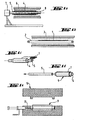
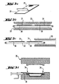
- Parts (a), (b), (c), (d), (e), (f) and (g) of Figure 1 represent very schematically different stages of a process according to the present invention.
- a fabric 1 consisting of glass filaments and filaments of thermoplastic organic material (for example polypropylene) intimately mixed is deposited on a support 2 and preheated in a hot air or radiation oven or tunnel infrared 3 (part b).
- a liner 4 in the form of a tube (for example polypropylene) carried by a rigid support 5 is preheated in an oven 6, the rigid support being rotated at using a motor 7 and an axis 8 in order to have a uniform preheating.
- the fabric 1 is then wrapped around the liner 4 (part c), the rigid support 5 removed (part d) and the preheated liner / structure 9 assembly is placed in a heated compression mold 10.
- a needle 11 is then introduced in the liner (part e) and after closing the mold, air is injected in the liner at a pressure higher than 40 bars (part f).
- the air is exhausted, the mold open, and the composite part removed from the mold (part g).
- this part having a section hollow central unit, as shown in part i and joined edges 12 can be used as fixings of the part or can possibly be cut to keep only the hollow section part.
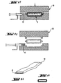
- Parts (a), (b), (c), (d), (e), (f) and (g) of Figure 2 represent very schematically different stages of a second embodiment of the method according to the present invention.
- a fabric 20 consisting of composite glass / organic thermoplastic yarns and coated on one of its faces with a waterproof film 21 (part a of FIG. 2) is placed on a support 22 then is preheated in an oven 23 (part b) before being rolled up on itself so that the film is at the interior (part c).
- the preheated fabric / film assembly 24 is placed in a heated compression mold 25.
- a needle 26 is then introduced on the whole (part d) and after closing the mold, air is injected at a pressure higher than 40 bars (part e). After consolidation of the molded part, the air is exhausted, the mold opened, and the composite part removed of the mold (part f).
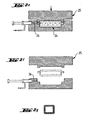
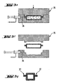
- Parts (a), (b), (c), (d), (e), (f) and (g) of Figure 3 represent very schematically different stages of a third mode of carrying out the method according to the present invention.
- two fabrics 30, of the type as shown in FIG. a these fabrics being each made of composite glass / organic matter thermoplastic and each coated on one side with a film sealed 31 are placed on a support 32 and then preheated in an oven 33 (part b).
- the fabrics are joined so that that the films are facing each other and thus form the pocket inflatable waterproof (the edges 34 of the fabrics being held together for molding in order to ensure watertightness) and the preheated fabric assembly provided with films is placed in a heated compression mold 35.
- a needle 36 is then introduced into the assembly (part d) and after closing the mold, air is injected at a pressure greater than 40 bars (part e). After consolidation of the molded part, the air is evacuated, the open mold, and the composite part removed from the mold (part f).
- the part whose section is represented in part g, this part having a hollow section and prominent edges 37, these edges being able to fulfill certain functions (for example being able to serve of fixings or stiffeners of the part) or possibly able be deburred.
- the molded articles which can be produced by the process according to the invention are for example bumper beams, beams of protection, energy absorbers for motor vehicles, structural parts for boats, support sleepers, car doors, rear floors or shelves, etc.
Landscapes
- Engineering & Computer Science (AREA)
- Mechanical Engineering (AREA)
- Manufacturing & Machinery (AREA)
- Chemical & Material Sciences (AREA)
- Composite Materials (AREA)
- Casting Or Compression Moulding Of Plastics Or The Like (AREA)
- Moulding By Coating Moulds (AREA)
- Laminated Bodies (AREA)
- Separation Using Semi-Permeable Membranes (AREA)
- Reinforced Plastic Materials (AREA)
- Manufacture Of Alloys Or Alloy Compounds (AREA)
- Superconductors And Manufacturing Methods Therefor (AREA)
Applications Claiming Priority (3)
| Application Number | Priority Date | Filing Date | Title |
|---|---|---|---|
| FR9905657 | 1999-05-04 | ||
| FR9905657A FR2793186B1 (fr) | 1999-05-04 | 1999-05-04 | Produits composites creux et procede de fabrication |
| PCT/FR2000/001211 WO2000066347A1 (fr) | 1999-05-04 | 2000-05-04 | Produits composites creux et procede de fabrication |
Publications (2)
| Publication Number | Publication Date |
|---|---|
| EP1175295A1 EP1175295A1 (fr) | 2002-01-30 |
| EP1175295B1 true EP1175295B1 (fr) | 2003-03-05 |
Family
ID=9545196
Family Applications (1)
| Application Number | Title | Priority Date | Filing Date |
|---|---|---|---|
| EP00925393A Expired - Lifetime EP1175295B1 (fr) | 1999-05-04 | 2000-05-04 | Produits composites creux et procede de fabrication |
Country Status (17)
| Country | Link |
|---|---|
| US (1) | US6955784B1 (zh) |
| EP (1) | EP1175295B1 (zh) |
| JP (1) | JP2002542966A (zh) |
| KR (1) | KR100615923B1 (zh) |
| CN (1) | CN1116161C (zh) |
| AT (1) | ATE233656T1 (zh) |
| AU (1) | AU773228B2 (zh) |
| BR (1) | BR0010265B1 (zh) |
| CA (1) | CA2372607A1 (zh) |
| DE (1) | DE60001551T2 (zh) |
| ES (1) | ES2193067T3 (zh) |
| FR (1) | FR2793186B1 (zh) |
| MX (1) | MXPA01011090A (zh) |
| NO (1) | NO319546B1 (zh) |
| NZ (1) | NZ515234A (zh) |
| TR (1) | TR200103152T2 (zh) |
| WO (1) | WO2000066347A1 (zh) |
Cited By (1)
| Publication number | Priority date | Publication date | Assignee | Title |
|---|---|---|---|---|
| WO2019214951A1 (de) | 2018-05-11 | 2019-11-14 | Herone Gmbh | Vorrichtung und verfahren zum kontinuierlichen blasformen faserverstärkter thermoplastischer hohlprofile mit einem konstanten oder sich änderndem querschnitt |
Families Citing this family (20)
| Publication number | Priority date | Publication date | Assignee | Title |
|---|---|---|---|---|
| US20050258575A1 (en) * | 2001-03-13 | 2005-11-24 | Christian Kruse | Non-isothermal method for fabricating hollow composite parts |
| KR100612615B1 (ko) * | 2003-05-16 | 2006-08-17 | 한국과학기술원 | 하이브리드 복합재료 저널베어링 구조 및 그러한 구조를갖는 저널베어링의 제조방법 |
| DE10338109B4 (de) * | 2003-05-28 | 2007-09-27 | Peguform Gmbh | Verfahren zur Herstellung eines Verbundbauteils |
| DE102006043688A1 (de) * | 2006-09-18 | 2008-03-27 | BSH Bosch und Siemens Hausgeräte GmbH | Verfahren zur Herstellung eines Warmwasserspeichers |
| US8858857B2 (en) * | 2007-03-12 | 2014-10-14 | Geoffrey Michael Wood | Process for the rapid fabrication of composite gas cylinders and related shapes |
| JP4429341B2 (ja) * | 2007-08-01 | 2010-03-10 | トヨタ自動車株式会社 | フランジ付き繊維強化樹脂中空部品 |
| GB0803823D0 (en) | 2008-02-29 | 2008-04-09 | Victrex Mfg Ltd | Composite materials |
| CN101992511B (zh) * | 2009-08-14 | 2013-08-21 | 陈法胜 | 可变化初胚尺寸的模制方法 |
| DE102009057498A1 (de) * | 2009-12-10 | 2011-06-16 | Rehau Ag + Co. | Verfahren zur Herstellung eines faserverstärkten Kunststoff-Hohlprofils |
| EP2347890A1 (de) * | 2010-06-24 | 2011-07-27 | ISE Automotive GmbH | Verfahren zur Herstellung eines zumindest abschnittsweise als Hohlprofil ausgebildeten Rahmenbauteils eines Kraftfahrzeuges |
| DE102010056240A1 (de) * | 2010-10-26 | 2012-04-26 | Rehau Ag + Co. | Verfahren zur Herstellung von endlosfaserverstärkten Kunststoffhohlformkörpern mit einer thermoplastischen Kunststoffmatrix, sowie ein endlosfaserverstärkter Kunststoffhohlformkörper und ein Kraftfahrzeug mit einem endlosfaserverstärkten Kunststoffhohlformkörper |
| CN103826824B (zh) | 2011-07-27 | 2016-12-21 | 弗莱克斯电子有限责任公司 | 复合组件的温度控制成型 |
| CN103331899B (zh) * | 2013-07-17 | 2015-06-24 | 厦门新旺新材料科技有限公司 | 一种复材加工成型气袋 |
| US10195782B2 (en) * | 2013-12-06 | 2019-02-05 | Unique Fabricating Inc | Air filled gasket |
| KR20150072178A (ko) * | 2013-12-19 | 2015-06-29 | 현대자동차주식회사 | 차량용 백빔 |
| CN104589671A (zh) * | 2014-12-17 | 2015-05-06 | 南京航空航天大学 | 一种复合材料的微波-液压成型方法和装置 |
| CN104647674B (zh) * | 2015-02-12 | 2016-09-21 | 贵州省材料产业技术研究院 | 自发热膨胀压力袋成型树脂纤维复合材料的方法 |
| CN107089049B (zh) * | 2016-02-17 | 2019-03-29 | 厦门市豪尔新材料股份有限公司 | 一种高强度纤维复材的制备方法 |
| JP7287323B2 (ja) * | 2020-03-25 | 2023-06-06 | トヨタ自動車株式会社 | 繊維強化樹脂成形品の製造方法および製造装置 |
| CN113715367B (zh) * | 2021-07-16 | 2022-08-09 | 北京科技大学 | 一种管梁零件制备工艺及管梁零件 |
Family Cites Families (7)
| Publication number | Priority date | Publication date | Assignee | Title |
|---|---|---|---|---|
| IE69047B1 (en) | 1989-03-23 | 1996-08-07 | Gary Harold Gregory Hen Thorpe | Liquid transfer devices |
| US5176868A (en) * | 1991-01-24 | 1993-01-05 | Prince Manufacturing, Inc. | Long fiber reinforced thermoplastic frame especially for a tennis racquet |
| FR2702778B1 (fr) | 1993-03-18 | 1995-05-05 | Vetrotex France Sa | Procédé et dispositif de formation d'un fil composite. |
| US5419554A (en) * | 1993-08-30 | 1995-05-30 | Quadrax Corporation | Sports racket frame |
| US5795423A (en) * | 1996-12-05 | 1998-08-18 | Ford Global Technologies, Inc. | Method for manufacturing a fiber reinforced article |
| SE509503C2 (sv) * | 1997-05-12 | 1999-02-01 | Volvo Ab | Arrangemang, förfarande och hålkropp vid formning av plastdetaljer |
| US6565793B1 (en) * | 1998-09-11 | 2003-05-20 | Essef Corporation | Method for fabricating composite pressure vessels |
-
1999
- 1999-05-04 FR FR9905657A patent/FR2793186B1/fr not_active Expired - Fee Related
-
2000
- 2000-05-04 NZ NZ515234A patent/NZ515234A/en unknown
- 2000-05-04 KR KR1020017013975A patent/KR100615923B1/ko not_active IP Right Cessation
- 2000-05-04 AU AU44133/00A patent/AU773228B2/en not_active Ceased
- 2000-05-04 WO PCT/FR2000/001211 patent/WO2000066347A1/fr active IP Right Grant
- 2000-05-04 BR BRPI0010265-2A patent/BR0010265B1/pt not_active IP Right Cessation
- 2000-05-04 EP EP00925393A patent/EP1175295B1/fr not_active Expired - Lifetime
- 2000-05-04 US US09/959,737 patent/US6955784B1/en not_active Expired - Fee Related
- 2000-05-04 JP JP2000615212A patent/JP2002542966A/ja not_active Withdrawn
- 2000-05-04 TR TR2001/03152T patent/TR200103152T2/xx unknown
- 2000-05-04 MX MXPA01011090A patent/MXPA01011090A/es active IP Right Grant
- 2000-05-04 CN CN00809919A patent/CN1116161C/zh not_active Expired - Fee Related
- 2000-05-04 AT AT00925393T patent/ATE233656T1/de not_active IP Right Cessation
- 2000-05-04 DE DE60001551T patent/DE60001551T2/de not_active Expired - Lifetime
- 2000-05-04 ES ES00925393T patent/ES2193067T3/es not_active Expired - Lifetime
- 2000-05-04 CA CA002372607A patent/CA2372607A1/en not_active Abandoned
-
2001
- 2001-11-02 NO NO20015375A patent/NO319546B1/no unknown
Cited By (3)
| Publication number | Priority date | Publication date | Assignee | Title |
|---|---|---|---|---|
| US11667068B2 (en) | 2018-03-11 | 2023-06-06 | Herone Gmbh | Device and method for continuously blow molding fiber-reinforced thermoplastic hollow profiles having a constant or changing cross-section |
| WO2019214951A1 (de) | 2018-05-11 | 2019-11-14 | Herone Gmbh | Vorrichtung und verfahren zum kontinuierlichen blasformen faserverstärkter thermoplastischer hohlprofile mit einem konstanten oder sich änderndem querschnitt |
| DE102018111283B4 (de) | 2018-05-11 | 2022-02-17 | Herone Gmbh | Vorrichtung, Verfahren und Verwendung der Vorrichtung zum semikontinuierlichen Blasformen faserverstärkter thermoplastischer Hohlprofile mit einem konstanten oder sich änderndem Querschnitt |
Also Published As
| Publication number | Publication date |
|---|---|
| CN1359328A (zh) | 2002-07-17 |
| ES2193067T3 (es) | 2003-11-01 |
| DE60001551T2 (de) | 2003-12-11 |
| CN1116161C (zh) | 2003-07-30 |
| FR2793186B1 (fr) | 2001-06-15 |
| CA2372607A1 (en) | 2000-11-09 |
| ATE233656T1 (de) | 2003-03-15 |
| JP2002542966A (ja) | 2002-12-17 |
| NO20015375D0 (no) | 2001-11-02 |
| AU773228B2 (en) | 2004-05-20 |
| NO319546B1 (no) | 2005-08-29 |
| DE60001551D1 (de) | 2003-04-10 |
| WO2000066347A1 (fr) | 2000-11-09 |
| BR0010265B1 (pt) | 2009-08-11 |
| AU4413300A (en) | 2000-11-17 |
| FR2793186A1 (fr) | 2000-11-10 |
| EP1175295A1 (fr) | 2002-01-30 |
| US6955784B1 (en) | 2005-10-18 |
| MXPA01011090A (es) | 2003-07-21 |
| TR200103152T2 (tr) | 2002-04-22 |
| KR100615923B1 (ko) | 2006-08-28 |
| NZ515234A (en) | 2003-05-30 |
| BR0010265A (pt) | 2002-02-13 |
| NO20015375L (no) | 2001-01-02 |
| KR20020016780A (ko) | 2002-03-06 |
Similar Documents
| Publication | Publication Date | Title |
|---|---|---|
| EP1175295B1 (fr) | Produits composites creux et procede de fabrication | |
| EP0865900B1 (fr) | Procédé de fabrication d'une pièce de grandes dimensions en matériau composite et pale d'hélice, en particulier d'éolienne, fabriqué selon ce procédé | |
| EP0888471B1 (fr) | Procede et dispositif de fabrication de plaques composites | |
| FR2779379A1 (fr) | Procede de realisation d'un panneau de structure composite renforcee du type sandwich a ame alveolaire et panneau realise selon un tel procede | |
| EP1373621A1 (fr) | Procede et dispositif de fabrication d'une plaque composite a renfort fibreux multiaxial | |
| EP1226298B1 (fr) | Procede et dispositif de fabrication de plaques composites | |
| FR2914874A1 (fr) | Procede de moulage de produits composites creux par extrusion-soufflage, dispositif utilise et produits obtenus | |
| EP0447479A1 (fr) | Procede et installation pour la fabrication d'un objet estampe en un materiau composite thermoplastique | |
| FR2844472A1 (fr) | Procede de fabrication de produits composites par rotomoulage et produits obtenus | |
| FR2779988A1 (fr) | Procede et dispositif de moulage de produits composites thermoplastiques | |
| EP0133119A2 (fr) | Demi-produit destiné à la fabrication de pièces en matière thermoplastique et son procédé de fabrication | |
| EP1847379B1 (fr) | Procédé d'assemblage de bandes multicouches | |
| EP0221982B1 (fr) | Materiau stratifie a base de resine thermoplastique et procede pour sa fabrication | |
| FR2957296A1 (fr) | Procede pour fabriquer un reservoir a carburant et son utilisation dans un vehicule hybride | |
| FR2464235A1 (fr) | Procede pour la production sans moule de pieces de forme poreuses en verre quartzeux et utilisation desdites pieces de forme | |
| FR2732266A1 (fr) | Element de construction multicouche ainsi que son procede de fabrication | |
| EP0691902B1 (fr) | Procede de fabrication de pieces renforcees en matiere thermoplastique et pieces obtenues par ce procede | |
| EP1799753A1 (fr) | Feuille de preimpregne a fils lies | |
| FR2478522A1 (fr) | Methode de soufflage horizontal de corps creux et produit obtenu | |
| WO2005068151A1 (fr) | Procede de fabrication d'une piece moulee | |
| FR3120812A1 (fr) | Preforme realisee par tricotage, produit composite incorporant une telle preforme et procedes de fabrication | |
| FR2582255A1 (fr) | Procede de fabrication d'un materiau stratifie a base de resines thermoplastiques et articles stratifies obtenus a l'aide d'un tel materiau | |
| BE820152R (fr) | Procede de moulage d'objets a plusieurs couches | |
| EP0479687A1 (fr) | Recipient creux semi-rigide en matière plastique multichouche, son procédé de fabrication et son utilisation | |
| EP0712721A1 (fr) | Procédé de fabrication d'un ski collé comprenant une étape de préparation de renfort par voie humide |
Legal Events
| Date | Code | Title | Description |
|---|---|---|---|
| PUAI | Public reference made under article 153(3) epc to a published international application that has entered the european phase |
Free format text: ORIGINAL CODE: 0009012 |
|
| 17P | Request for examination filed |
Effective date: 20011109 |
|
| AK | Designated contracting states |
Kind code of ref document: A1 Designated state(s): AT BE CH CY DE DK ES FI FR GB GR IE IT LI LU MC NL PT SE |
|
| GRAG | Despatch of communication of intention to grant |
Free format text: ORIGINAL CODE: EPIDOS AGRA |
|
| 17Q | First examination report despatched |
Effective date: 20020605 |
|
| RAP1 | Party data changed (applicant data changed or rights of an application transferred) |
Owner name: SAINT-GOBAIN VETROTEX FRANCE S.A. |
|
| GRAG | Despatch of communication of intention to grant |
Free format text: ORIGINAL CODE: EPIDOS AGRA |
|
| GRAH | Despatch of communication of intention to grant a patent |
Free format text: ORIGINAL CODE: EPIDOS IGRA |
|
| GRAH | Despatch of communication of intention to grant a patent |
Free format text: ORIGINAL CODE: EPIDOS IGRA |
|
| GRAA | (expected) grant |
Free format text: ORIGINAL CODE: 0009210 |
|
| AK | Designated contracting states |
Designated state(s): AT BE CH CY DE DK ES FI FR GB GR IE IT LI LU MC NL PT SE |
|
| PG25 | Lapsed in a contracting state [announced via postgrant information from national office to epo] |
Ref country code: NL Free format text: LAPSE BECAUSE OF FAILURE TO SUBMIT A TRANSLATION OF THE DESCRIPTION OR TO PAY THE FEE WITHIN THE PRESCRIBED TIME-LIMIT Effective date: 20030305 Ref country code: GR Free format text: LAPSE BECAUSE OF FAILURE TO SUBMIT A TRANSLATION OF THE DESCRIPTION OR TO PAY THE FEE WITHIN THE PRESCRIBED TIME-LIMIT Effective date: 20030305 Ref country code: FI Free format text: LAPSE BECAUSE OF FAILURE TO SUBMIT A TRANSLATION OF THE DESCRIPTION OR TO PAY THE FEE WITHIN THE PRESCRIBED TIME-LIMIT Effective date: 20030305 Ref country code: AT Free format text: LAPSE BECAUSE OF FAILURE TO SUBMIT A TRANSLATION OF THE DESCRIPTION OR TO PAY THE FEE WITHIN THE PRESCRIBED TIME-LIMIT Effective date: 20030305 Ref country code: IE Free format text: LAPSE BECAUSE OF FAILURE TO SUBMIT A TRANSLATION OF THE DESCRIPTION OR TO PAY THE FEE WITHIN THE PRESCRIBED TIME-LIMIT Effective date: 20030305 |
|
| REG | Reference to a national code |
Ref country code: GB Ref legal event code: FG4D Free format text: NOT ENGLISH |
|
| REG | Reference to a national code |
Ref country code: CH Ref legal event code: EP |
|
| REG | Reference to a national code |
Ref country code: IE Ref legal event code: FG4D Free format text: FRENCH |
|
| REF | Corresponds to: |
Ref document number: 60001551 Country of ref document: DE Date of ref document: 20030410 Kind code of ref document: P |
|
| PG25 | Lapsed in a contracting state [announced via postgrant information from national office to epo] |
Ref country code: CY Free format text: LAPSE BECAUSE OF FAILURE TO SUBMIT A TRANSLATION OF THE DESCRIPTION OR TO PAY THE FEE WITHIN THE PRESCRIBED TIME-LIMIT Effective date: 20030504 Ref country code: LU Free format text: LAPSE BECAUSE OF NON-PAYMENT OF DUE FEES Effective date: 20030504 |
|
| REG | Reference to a national code |
Ref country code: CH Ref legal event code: NV Representative=s name: KELLER & PARTNER PATENTANWAELTE AG |
|
| PG25 | Lapsed in a contracting state [announced via postgrant information from national office to epo] |
Ref country code: MC Free format text: LAPSE BECAUSE OF NON-PAYMENT OF DUE FEES Effective date: 20030531 |
|
| PG25 | Lapsed in a contracting state [announced via postgrant information from national office to epo] |
Ref country code: DK Free format text: LAPSE BECAUSE OF FAILURE TO SUBMIT A TRANSLATION OF THE DESCRIPTION OR TO PAY THE FEE WITHIN THE PRESCRIBED TIME-LIMIT Effective date: 20030605 Ref country code: SE Free format text: LAPSE BECAUSE OF FAILURE TO SUBMIT A TRANSLATION OF THE DESCRIPTION OR TO PAY THE FEE WITHIN THE PRESCRIBED TIME-LIMIT Effective date: 20030605 |
|
| PG25 | Lapsed in a contracting state [announced via postgrant information from national office to epo] |
Ref country code: PT Free format text: LAPSE BECAUSE OF FAILURE TO SUBMIT A TRANSLATION OF THE DESCRIPTION OR TO PAY THE FEE WITHIN THE PRESCRIBED TIME-LIMIT Effective date: 20030606 |
|
| GBT | Gb: translation of ep patent filed (gb section 77(6)(a)/1977) | ||
| NLV1 | Nl: lapsed or annulled due to failure to fulfill the requirements of art. 29p and 29m of the patents act | ||
| REG | Reference to a national code |
Ref country code: IE Ref legal event code: FD4D Ref document number: 1175295E Country of ref document: IE |
|
| REG | Reference to a national code |
Ref country code: ES Ref legal event code: FG2A Ref document number: 2193067 Country of ref document: ES Kind code of ref document: T3 |
|
| PLBE | No opposition filed within time limit |
Free format text: ORIGINAL CODE: 0009261 |
|
| STAA | Information on the status of an ep patent application or granted ep patent |
Free format text: STATUS: NO OPPOSITION FILED WITHIN TIME LIMIT |
|
| 26N | No opposition filed |
Effective date: 20031208 |
|
| PGFP | Annual fee paid to national office [announced via postgrant information from national office to epo] |
Ref country code: GB Payment date: 20050504 Year of fee payment: 6 |
|
| PGFP | Annual fee paid to national office [announced via postgrant information from national office to epo] |
Ref country code: CH Payment date: 20050517 Year of fee payment: 6 |
|
| PGFP | Annual fee paid to national office [announced via postgrant information from national office to epo] |
Ref country code: BE Payment date: 20050601 Year of fee payment: 6 |
|
| PG25 | Lapsed in a contracting state [announced via postgrant information from national office to epo] |
Ref country code: GB Free format text: LAPSE BECAUSE OF NON-PAYMENT OF DUE FEES Effective date: 20060504 |
|
| PG25 | Lapsed in a contracting state [announced via postgrant information from national office to epo] |
Ref country code: BE Free format text: LAPSE BECAUSE OF NON-PAYMENT OF DUE FEES Effective date: 20060531 Ref country code: LI Free format text: LAPSE BECAUSE OF NON-PAYMENT OF DUE FEES Effective date: 20060531 Ref country code: CH Free format text: LAPSE BECAUSE OF NON-PAYMENT OF DUE FEES Effective date: 20060531 |
|
| REG | Reference to a national code |
Ref country code: CH Ref legal event code: PL |
|
| GBPC | Gb: european patent ceased through non-payment of renewal fee |
Effective date: 20060504 |
|
| BERE | Be: lapsed |
Owner name: S.A. *SAINT-GOBAIN VETROTEX FRANCE Effective date: 20060531 |
|
| PGFP | Annual fee paid to national office [announced via postgrant information from national office to epo] |
Ref country code: IT Payment date: 20120524 Year of fee payment: 13 |
|
| PG25 | Lapsed in a contracting state [announced via postgrant information from national office to epo] |
Ref country code: IT Free format text: LAPSE BECAUSE OF NON-PAYMENT OF DUE FEES Effective date: 20130504 |
|
| REG | Reference to a national code |
Ref country code: FR Ref legal event code: PLFP Year of fee payment: 16 |
|
| PGFP | Annual fee paid to national office [announced via postgrant information from national office to epo] |
Ref country code: ES Payment date: 20150526 Year of fee payment: 16 Ref country code: DE Payment date: 20150528 Year of fee payment: 16 |
|
| PGFP | Annual fee paid to national office [announced via postgrant information from national office to epo] |
Ref country code: FR Payment date: 20150519 Year of fee payment: 16 |
|
| REG | Reference to a national code |
Ref country code: DE Ref legal event code: R119 Ref document number: 60001551 Country of ref document: DE |
|
| REG | Reference to a national code |
Ref country code: FR Ref legal event code: ST Effective date: 20170131 |
|
| PG25 | Lapsed in a contracting state [announced via postgrant information from national office to epo] |
Ref country code: DE Free format text: LAPSE BECAUSE OF NON-PAYMENT OF DUE FEES Effective date: 20161201 Ref country code: FR Free format text: LAPSE BECAUSE OF NON-PAYMENT OF DUE FEES Effective date: 20160531 |
|
| PG25 | Lapsed in a contracting state [announced via postgrant information from national office to epo] |
Ref country code: ES Free format text: LAPSE BECAUSE OF NON-PAYMENT OF DUE FEES Effective date: 20160505 |
|
| REG | Reference to a national code |
Ref country code: ES Ref legal event code: FD2A Effective date: 20181129 |