EP1175109A2 - MPEG PCR jitter, frequency offset and drift rate measurements - Google Patents
MPEG PCR jitter, frequency offset and drift rate measurements Download PDFInfo
- Publication number
- EP1175109A2 EP1175109A2 EP01305946A EP01305946A EP1175109A2 EP 1175109 A2 EP1175109 A2 EP 1175109A2 EP 01305946 A EP01305946 A EP 01305946A EP 01305946 A EP01305946 A EP 01305946A EP 1175109 A2 EP1175109 A2 EP 1175109A2
- Authority
- EP
- European Patent Office
- Prior art keywords
- pcr
- jitter
- frequency offset
- drift rate
- rate
- Prior art date
- Legal status (The legal status is an assumption and is not a legal conclusion. Google has not performed a legal analysis and makes no representation as to the accuracy of the status listed.)
- Granted
Links
Images


Classifications
-
- H—ELECTRICITY
- H04—ELECTRIC COMMUNICATION TECHNIQUE
- H04N—PICTORIAL COMMUNICATION, e.g. TELEVISION
- H04N17/00—Diagnosis, testing or measuring for television systems or their details
- H04N17/004—Diagnosis, testing or measuring for television systems or their details for digital television systems
Definitions
- the present invention relates to the quality of compressed video signals, and more particularly to a method for measuring Motion Picture Engineering Group (MPEG) Program Clock Reference (PCR) jitter, frequency offset and drift rate with a selectable, constant measurement bandwidth over non-uniform PCR arrival times and a variable PCR rate.
- MPEG Motion Picture Engineering Group
- PCR Program Clock Reference
- PCR Primary Clock Reference
- Frequency offset is the difference between the actual value and the nominal frequency of the STC at the encoder.
- the limit is set at +/-810 Hz or normalized as +/-30 ppm.
- Frequency rate of change or drift rate is the "speed" at which the frequency of the program STC varies with time, i.e., it is the first derivative of the frequency with respect to time or the second derivative of phase with respect to time.
- the limit is set to 75 mHz/sec for the 27 MHz program STC or, normalized to the STC frequency of 27 MHz, as 10 ppm/hr.
- the phase tolerance is set to +/-500 ns which represents the maximum error of a PCR value with respect to the value it should have due to its time position in the TS.
- the limits for frequency offset and drift rate are imposed for the STC as it is represented by the values of the corresponding PCR fields. They include the effects of the program STC and any possible errors in the PCR calculation.
- the limit of 500 ns is not imposed on the program STC, but on the accuracy representing the PCR values with respect to their position in the TS.
- the PCR errors are fully equivalent to phase and jitter errors when the PCR values are used at the decoding point to reconstruct the STC.
- a method for testing program STC frequency error, drift rate and PCR jitter is described in ISO/IEC 13818-9, 1996. This test is carried out for one program in the TS at a time.
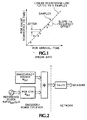
- the procedure uses a plot of PCR values, which represent the program STC time at which the data was transmitted, against PCR arrival times, as illustrated in Fig. 1.
- the arrival times are plotted on the X axis and represent accurate time at the receiver.
- the PCR values are plotted on the Y axis.
- a linear regression line is fitted to N samples and the slope of the line minus one is the frequency offset.
- the jitter is defined as the distance of the PCR values above/below the line.
- This method has the problem of determining how large N should be to accumulate enough samples. If N is too large, low frequency timing perturbations, i.e., wander, cause overly large measured values of jitter when using the straight line curve fit rather than a quadratic fit. For the linear fit the slope of this straight line is used to estimate the frequency offset. But since the frequency offset often drifts or wanders, the jitter values may be unduly large due to these wander effects. Since these values far exceed the jitter specification but are tracked by the decoder's phase locked loop (PLL), if the drift rate is below limits they are of no concern. Therefore they should not be in the jitter measurement and should be separately quantified with respect to drift rate.
- PLL phase locked loop
- drift rate ⁇ small timing variations that are well within the jitter specification may, and often do, far exceed the drift rate specification since it is proportional to the second derivative of the timing or phase error. Therefore the drift rate measurement should be lowpass filtered to not include timing errors with peak variations within acceptable jitter limits. It is preferred to do a quadratic curve fit also to verify the compliance with frequency drift rate but, if N is too small, timing variations within the jitter limit cause the drift rate estimate to always exceed specification. If the PCRs do not arrive with sufficient regularity, then the regenerated STC may jitter or drift. The receiver/decoder may even go out of lock.
- Timing effects visible at a TS interface point may be modeled as indicated in Fig. 2.
- This is an idealized model of an encoder/remultiplexer and communication network.
- the components of the model in the encoder are specific to the PCR for a particular program stream, whereas the components in the network relate to the entire TS.
- the model has a system clock frequency oscillator with a nominal frequency, F, such as 27 MHz, but whose actual frequency deviates from this by a function, f dev (p,t).
- F nominal frequency
- f dev (p,t) This function depends on the time (t) and is specific to a single program stream (p). This represents frequency offset for the nominal frequency which according to the MPEG standard should stay between specified tolerances.
- Drift rate is the rate of change with time of f dev (p,t). The drift rate also should be below limits set by the MPEG standard.
- the system clock frequency oscillator drives a PCR counter which generates an idealized PCR count, N p,i , where (p) refers to the specific program stream and (i) refers to the bit position in the TS. To this is added a value from a PCR inaccuracy source, M p,i , to create the PCR value seen in the TS, P p,i .
- M p,i a PCR inaccuracy source
- the TS is being transmitted at a constant bit rate, R nom .
- the communication network beyond the encoder varies the arrival time of MPEG packets from their nominal arrival time by introducing a variable delay, J(i), which is the delay in seconds for the ith bit in the TS.
- the nominal arrival time is calculated from R nom and the bit index in the TS.
- J(i) represents the jitter in the network delay and its mean value over all time is defined to be zero ⁇ this sets the value of D.
- J(i) + M p,i is the overall PCR jitter which has a maximum error specification set in the MPEG standard.
- a constant bandwidth method for determining the frequency offset, drift rate and jitter is preferred so that all measurement systems measure the same values on the same program PCRs at the stated bandwidth. Also a constant bandwidth measurement has more physical meaning in terms of how the recovered STC in the MPEG decoder responds to PCR errors since the decoder typically has a constant bandwidth and operates independently of PCR arrival intervals or PCR average rate.
- What is desired is a method of measuring MPEG PCR jitter, frequency offset and drift rate with a selectable, constant measurement bandwidth over non-uniform PCR arrival times and a variable PCR rate.
- the present invention provides a method of measuring MPEG PCR jitter, frequency offset and drift rate with a selectable, constant measurement bandwidth over non-uniform PCR arrival times and a variable PCR rate.
- the selected constant bandwidth demarcates jitter from wander and is derived from a limit mask based upon the standards specified for jitter, frequency and drift rate in the MPEG standard.
- the PCR arrival times are measured with a reference clock and are converted to measured PCR intervals, and the measured PCR intervals, PCR values and selected constant bandwidth are input to a set of difference equations to derive the jitter, frequency and drift rate values.
- the set of difference equations is derived either from a type II phase locked loop or from least mean square (LMS) linear and quadratic estimators.
- LMS least mean square
- Fig. 1 is a graphical diagram view for estimating frequency offset and jitter according to the prior art.
- Fig. 2 is block diagram view of a model indicating sources of variation in PCR values for a program stream in an MPEG Transport Stream.
- Fig. 3 is a graphical diagram view of a frequency offset drift and jitter mask according to the present invention.
- Fig. 4 is a simplified, general diagram view of a measurement filter for measuring frequency offset, dither and jitter according to the present invention.
- Fig. 5 is a block diagram view of a phase locked loop (PLL) representation for measuring frequency offset, dither and jitter according to the present invention.
- PLL phase locked loop
- Fig. 6 is a block diagram view of an equivalent circuit to that of Fig. 5 for deriving a set of difference equations according to the present invention.
- Fig. 7 is a block diagram view of an equivalent circuit using least mean square first and second order estimators for deriving a set of difference equations according to the present invention.
- Figs. 8a and 8b are comparisons of FIR linear and quadratic regression filters with a differentiator plus lowpass filter and dual differentiators plus lowpass filters respectively according to the present invention.
- Each method has a single control parameter ⁇ the measurement bandwidth (BW) which is a demarcation frequency between jitter and wander -- that is selectable and constant independently of the average PCR rate.
- BW measurement bandwidth
- Each method has three discrete time output measurement results: (1) STC frequency offset, FO(n); (2) STC frequency drift rate, DR(n); and (3) PCR jitter, Jit(n).
- the equations for the first method are derived from a hybrid digital-analog phase locked loop (PLL) model, shown in Fig. 5, where the three output parameters are extracted from various points in the resulting feedback control system. Additional high-pass filtering and scaling is added to Jit(n) to improve separation of wander components and scale the output to units of time per second. Additional low-pass filtering is added to FO(n) and DR(n) to improve rejection of jitter components.
- PLL phase locked loop
- the type II PLL shown in Fig. 5 has two ideal integrators -- a digital accumulator and a voltage controlled oscillator. This creates a second order highpass closed loop response at the output of the phase subtraction. Therefore below the loop bandwidth the response is proportional to drift rate and above the loop bandwidth the response is proportional to jitter.
- a first order highpass filter is added to the jitter measurement to remove the effects of drift rate.
- a lowpass filter is added at the drift rate output to remove the effects of jitter from that measurement.
- the filters are best implemented using digital signal processing (DSP) on the raw data and, since the PCR rate is the sample rate, the average PCR rate is determined and the coefficients adjusted to maintain approximately the correct measurement filter bandwidths and control loop damping.
- DSP digital signal processing
- the VCXO may be constructed from a subsystem having a free-running OCXO of 0.1 ppm accuracy and a FLL locking a VCXO with +/-30 ppm range. This may be used to calibrate the frequency offset output to 0.1 ppm accuracy if desired. Otherwise the VCXO may be used alone and it's frequency error or offset verified by applying a known, accurate frequency, and subtracting the error from subsequent measurements. This describes a PLL implementation as a hybrid DSP and analog signal processing method.
- a practical set of difference equations may be derived from the PLL model duplicating the closed-loop response such that frequency offset, drift rate and jitter may be measured with a selectable, fixed bandwidth independently of the non-uniform PCR arrival times.
- Such an equivalent circuit is shown in Fig. 6 for deriving such equations.
- the PCR(n) values are input to a differentiator, and the output from the differentiator is input to a second order lowpass filter for non-uniform sample intervals. Also input to the second order lowpass filter is the corresponding PCR_int(n) from the last received PCR(n-1).
- the filter output y(n) is multiplied by the overall open loop d.c.
- the filter outputs for two consecutive samples, y(n) and y(n-1), are input to a second differentiator to produce a jitter error output, J(n), which is in turn input to both a first order lowpass filter to derive the drift rate, DR(n), and a first order highpass filter to derive the jitter, Jit(n).
- y(n) 2*y(n-1)-y(n-2)-(y(n-1)-N1*y(n-2))*5.932*BW*PCR_int(n)+(PCR(n)-PCR(n-1))/Fo
- Fo 27MHz
- BW is the measurement bandwidth in Hertz
- N1 is a constant equal to 1/(1+pi*BW/60).
- y(n) frequency offset, FO(n) is y(n)*Godc-1 where Godc is a constant equal to (1-N1)*5.932*BW.
- drift rate, DR(n) is A2*DR(n-1)+(Godc/Tp)*J(n) where Tp is 1/(2*pi*.01) and A2 is exp(-1/30*Tp).
- DR(n) is post-filtered with a fixed bandwidth of 0.01 Hz and y(n) is initialized to 1/Godc to minimize settling time.
- the second method is derived from a linear filtering approximation to a least mean square (LMS) frequency offset estimator (linear-term coefficient) and LMS drift rate estimator (quadratic-term coefficient) of a simple second order time equation for the PCR values.
- LMS least mean square
- LMS drift rate estimator quadrature-term coefficient
- PCR_AT(n) as the measured arrival time of each of the received PCR(n) values using an accurate reference clock
- PCR(n) a+PCR_AT(n)*Fstc+(PCR_AT(n)) ⁇ 2*c+ ⁇ (PCR_AT(n)) cycles of Fstc.
- the last term is the jitter as a function of time.
- PCR_AT(n) is a random variable added to PCR(n) due to the combined effects of arrival time jitter and PCR(n) encoding error.
- PCR(n) values are themselves I.I.D, random variables.
- a is an initial phase error relative to the reference oscillator
- Fstc is the system timing clock frequency
- the jitter term now is in seconds of jitter and a is the initial phase offset in seconds and b is the frequency offset of the STC as a dimensionless ratio.
- This equation neglecting drift rate, is the equation for PCR(n)s allowing a linear regression or straight line fit of the data to be determined from estimates of the coefficients a and b to minimize the mean square error due to jitter.
- This provides the dual result of first determining STC frequency offset FO as the LMS estimate for b, and second the jitter by subtracting the FO effect due to b and the initial phase value a as suggested by the MPEG standard.
- a constant bandwidth filtering process may be constructed for non-uniform sampled data that is itself a function of the instantaneous sample interval in order to develop a constant bandwidth measurement that is independent of PCR rate. This is important since it allows a continuously updated filtering process to be mechanized to find practical and consistent estimates of the PCR jitter, STC frequency offset and drift rate for comparison to the published limits of the MPEG standard. Further since the bandwidth of the measurement is constant, a standardized demarcation frequency based on the STC drift rate and PCR accuracy specifications may be used to determine a practical and standardized filter bandwidth that has a direct relationship to the recovered STC clock characteristics in the MPEG decoder.
- LMS estimators frequency offset from linear regression and frequency drift rate from quadratic regression
- FIR finite impulse response
- a second order recursive Butterworth lowpass filter of bandwidth BW is cascaded with a differentiator.
- a cascade of the recursive LPF and the differentiator response is compared to the FIR LMS frequency offset estimator in Fig. 8a.
- a 3 rd order recursive Butterworth LPF of bandwidth BW cascaded with two differentiators is compared to the FIR LMS drift rate estimator in Fig. 8b.
- the PCR jitter may be determined by subtracting the estimated PCR values due to frequency offset by using the estimated value from the filtering process and applying a HPF to reject the drift rate components from the result.
- PCR_int(n) is derived from the PCR_AT(n) times and subtracted from the differentiation of the PCR(n) values, normalized, to produce a PCR(n) error value, Foo(n).
- Foo(n) is input to a first linear LMS estimator which includes a derivative function and a second order lowpass filter to produce the frequency offset, FO(n).
- the frequency offset is input to a second quadratic LMS estimator which includes a derivative function, differentiator and first order lowpass filter to produce the drift rate, DR(n).
- the frequency offset also is multiplied by the PCR_int(n) and the result subtracted from the PCR(n) error value to produce an instantaneous jitter value, JJ(n).
- the instantaneous jitter value is then processed by a cascade filter, having first a first order lowpass filter followed by a first order highpass filter, that produces the PCR jitter, Jit(n).
- the present invention provides a method of determining MPEG PCR jitter, frequency offset and drift rate from the PCR values arriving at non-uniform intervals and a selectable, constant bandwidth which is the frequency that separates wander from jitter using a set of difference equations derived either from a type II phase locked loop or from LMS first and second order estimators.
Landscapes
- Engineering & Computer Science (AREA)
- Health & Medical Sciences (AREA)
- Biomedical Technology (AREA)
- General Health & Medical Sciences (AREA)
- Multimedia (AREA)
- Signal Processing (AREA)
- Stabilization Of Oscillater, Synchronisation, Frequency Synthesizers (AREA)
- Synchronisation In Digital Transmission Systems (AREA)
- Dc Digital Transmission (AREA)
- Testing, Inspecting, Measuring Of Stereoscopic Televisions And Televisions (AREA)
- Compression Or Coding Systems Of Tv Signals (AREA)
Abstract
Description
For comparison a 3rd order recursive Butterworth LPF of bandwidth BW cascaded with two differentiators is compared to the FIR LMS drift rate estimator in Fig. 8b.
Claims (3)
- A method of measuring program clock reference (PCR) jitter, frequency offset and drift rate with a selectable constant measurement bandwidth over non-uniform PCR arrival times and a variable PCR rate comprising the steps of:measuring an interval between PCR arrival times with an asynchronous precision reference oscillator;fixing the selectable constant measurement bandwidth independently of the variable PCR rate, the fixed selectable constant measurement bandwidth demarcating a frequency between jitter and wander; andcalculating the PCR jitter, frequency offset and drift rate as a function of the interval between PCR arrival times, the PCR values at each PCR arrival time and the fixed selectable constant measurement bandwidth in the form of a set of difference equations.
- The method as recited in claim 1 wherein the set of difference equations is derived from a hybrid digital-analog phase locked loop (PLL) model where the jitter, frequency offset and drift rate are extracted from various points in the feedback control system for the PLL.
- The method as recited in claim 1 wherein the set of difference equations is derived from a linear filtering approximation to a least mean square (LMS) frequency offset and an LMS drift rate estimator of a simple second order time equation for the PCR values.
Applications Claiming Priority (2)
| Application Number | Priority Date | Filing Date | Title |
|---|---|---|---|
| US619243 | 1990-11-28 | ||
| US09/619,243 US6650719B1 (en) | 2000-07-19 | 2000-07-19 | MPEG PCR jitter, frequency offset and drift rate measurements |
Publications (3)
| Publication Number | Publication Date |
|---|---|
| EP1175109A2 true EP1175109A2 (en) | 2002-01-23 |
| EP1175109A3 EP1175109A3 (en) | 2002-02-06 |
| EP1175109B1 EP1175109B1 (en) | 2004-12-01 |
Family
ID=24481077
Family Applications (1)
| Application Number | Title | Priority Date | Filing Date |
|---|---|---|---|
| EP01305946A Expired - Lifetime EP1175109B1 (en) | 2000-07-19 | 2001-07-10 | MPEG PCR jitter, frequency offset and drift rate measurements |
Country Status (7)
| Country | Link |
|---|---|
| US (1) | US6650719B1 (en) |
| EP (1) | EP1175109B1 (en) |
| JP (1) | JP3971137B2 (en) |
| CN (1) | CN1263315C (en) |
| DE (1) | DE60107502T2 (en) |
| ES (1) | ES2231392T3 (en) |
| SG (1) | SG111022A1 (en) |
Cited By (2)
| Publication number | Priority date | Publication date | Assignee | Title |
|---|---|---|---|---|
| FR2897226A1 (en) * | 2006-02-08 | 2007-08-10 | Thales Sa | DEVICE FOR MEASURING PARAMETERS RELATING TO TEMPORAL STAMPLES NOTABLY PRESENTED IN STREAMS, AND FREQUENCY SYNTHESIZER |
| EP4451684A4 (en) * | 2021-12-15 | 2025-10-01 | Shenzhen Tcl New Tech Co Ltd | DATA PROCESSING METHOD AND SYSTEM, STORAGE MEDIUM AND TERMINAL DEVICE |
Families Citing this family (25)
| Publication number | Priority date | Publication date | Assignee | Title |
|---|---|---|---|---|
| FR2811846B1 (en) * | 2000-07-17 | 2002-09-27 | Thomson Multimedia Sa | METHOD AND DEVICE FOR READING RECORDED MPEG DATA TRANSMITTED ON AN IEEE 1394 BUS |
| US7304545B1 (en) | 2000-11-30 | 2007-12-04 | Marvell International Ltd. | High latency timing circuit |
| US6732286B1 (en) * | 2000-11-30 | 2004-05-04 | Marvell International, Ltd. | High latency timing circuit |
| US7860205B1 (en) * | 2001-09-18 | 2010-12-28 | Ciena Corporation | Clock synchronization using a weighted least squares error filtering technique |
| US7184506B2 (en) * | 2002-03-30 | 2007-02-27 | Broadcom Corporation | Frequency drift and phase error compensation in a VOFDM receiver |
| US7130368B1 (en) * | 2002-09-19 | 2006-10-31 | Nortel Network Limited | Clock recovery using a direct smoothing process |
| US7337344B2 (en) * | 2003-01-31 | 2008-02-26 | Point Grey Research Inc. | Methods and apparatus for synchronizing devices on different serial data buses |
| US7610161B2 (en) * | 2003-05-01 | 2009-10-27 | Tektronix, Inc. | Wander gamut display |
| US7397825B2 (en) * | 2004-03-10 | 2008-07-08 | Scientific-Atlanta, Inc. | Transport stream dejitterer |
| US7376158B2 (en) * | 2004-04-22 | 2008-05-20 | Scientific-Atlanta, Inc. | Rate limited control mechanism for MPEG PCR dejittering |
| EP1653747B1 (en) * | 2004-10-20 | 2015-08-19 | STMicroelectronics International N.V. | A system for clock recovery in digital video communication |
| US7778173B2 (en) * | 2005-01-04 | 2010-08-17 | Cisco Technology, Inc. | Clock recovery algorithm for remultiplexing MPEG-2 SPTSs and/or MPTSs in the presence of network jitter |
| US20060155961A1 (en) * | 2005-01-06 | 2006-07-13 | International Business Machines Corporation | Apparatus and method for reformatting instructions before reaching a dispatch point in a superscalar processor |
| US7221704B2 (en) | 2005-08-01 | 2007-05-22 | Marvell World Trade Ltd. | All digital implementation of clock spectrum spreading (dither) for low power/die area |
| US7817535B2 (en) * | 2005-11-02 | 2010-10-19 | Cisco Technology, Inc. | Method of fault tolerance and synchronous failover for broadcast video across the network |
| US8064484B2 (en) * | 2006-02-01 | 2011-11-22 | Symmetricom, Inc. | Enhanced clock control in packet networks |
| US7455844B2 (en) | 2006-03-29 | 2008-11-25 | Merial Limited | Vaccine against streptococci |
| CN100428802C (en) * | 2006-12-22 | 2008-10-22 | 清华大学 | A Method of Adaptive Multimedia Playing |
| KR100880179B1 (en) | 2007-04-09 | 2009-01-28 | (주)디티브이인터랙티브 | IP network quality measuring method and apparatus, and IP network quality measuring system |
| JP5105072B2 (en) * | 2008-02-19 | 2012-12-19 | Necエンジニアリング株式会社 | Timing information collection device |
| JP5185167B2 (en) * | 2009-03-12 | 2013-04-17 | 富士通テレコムネットワークス株式会社 | Jitter detection circuit and jitter detection method |
| US8514329B2 (en) | 2011-05-31 | 2013-08-20 | Motorola Mobility Llc | Jitter estimation for MPEG receivers |
| GB2514572B (en) * | 2013-05-29 | 2020-05-27 | Grass Valley Ltd | Re-timing sampled data |
| TWI682387B (en) * | 2018-10-24 | 2020-01-11 | 新唐科技股份有限公司 | Multi-tone communication system, multi-tone signal demodulation device and method thereof |
| CN112710636B (en) * | 2020-12-09 | 2022-05-24 | 深圳市科曼医疗设备有限公司 | A kind of detection method and detection device of specific protein concentration |
Family Cites Families (5)
| Publication number | Priority date | Publication date | Assignee | Title |
|---|---|---|---|---|
| US5805602A (en) * | 1995-09-25 | 1998-09-08 | Bell Atlantic Network Services, Inc. | Network monitoring system for cell delay variation |
| US5966387A (en) * | 1995-09-25 | 1999-10-12 | Bell Atlantic Network Services, Inc. | Apparatus and method for correcting jitter in data packets |
| US5774497A (en) | 1996-04-12 | 1998-06-30 | Hewlett-Packard Co | Method and apparatus for PCR jitter measurement in an MPEG-2 transport stream |
| US5883924A (en) | 1996-04-12 | 1999-03-16 | Hewlett Packard Company | Method and apparatus for PCR jitter measurement in an MPEG-2 transport stream using sliding window |
| KR100271236B1 (en) * | 1998-02-02 | 2000-11-01 | 김춘호 | Dpll for pcr clock recovery using a normalizing mathod |
-
2000
- 2000-07-19 US US09/619,243 patent/US6650719B1/en not_active Expired - Lifetime
-
2001
- 2001-06-20 SG SG200103781A patent/SG111022A1/en unknown
- 2001-07-10 EP EP01305946A patent/EP1175109B1/en not_active Expired - Lifetime
- 2001-07-10 DE DE60107502T patent/DE60107502T2/en not_active Expired - Lifetime
- 2001-07-10 ES ES01305946T patent/ES2231392T3/en not_active Expired - Lifetime
- 2001-07-18 JP JP2001218797A patent/JP3971137B2/en not_active Expired - Fee Related
- 2001-07-19 CN CN01123060.6A patent/CN1263315C/en not_active Expired - Fee Related
Cited By (3)
| Publication number | Priority date | Publication date | Assignee | Title |
|---|---|---|---|---|
| FR2897226A1 (en) * | 2006-02-08 | 2007-08-10 | Thales Sa | DEVICE FOR MEASURING PARAMETERS RELATING TO TEMPORAL STAMPLES NOTABLY PRESENTED IN STREAMS, AND FREQUENCY SYNTHESIZER |
| WO2007090858A1 (en) * | 2006-02-08 | 2007-08-16 | Thales | Device for measuring parameters relating to program clock references especially in streams, and frequency synthesiser |
| EP4451684A4 (en) * | 2021-12-15 | 2025-10-01 | Shenzhen Tcl New Tech Co Ltd | DATA PROCESSING METHOD AND SYSTEM, STORAGE MEDIUM AND TERMINAL DEVICE |
Also Published As
| Publication number | Publication date |
|---|---|
| ES2231392T3 (en) | 2005-05-16 |
| CN1263315C (en) | 2006-07-05 |
| EP1175109B1 (en) | 2004-12-01 |
| US6650719B1 (en) | 2003-11-18 |
| CN1340971A (en) | 2002-03-20 |
| EP1175109A3 (en) | 2002-02-06 |
| JP2002118862A (en) | 2002-04-19 |
| SG111022A1 (en) | 2005-05-30 |
| DE60107502T2 (en) | 2005-05-12 |
| DE60107502D1 (en) | 2005-01-05 |
| JP3971137B2 (en) | 2007-09-05 |
Similar Documents
| Publication | Publication Date | Title |
|---|---|---|
| EP1175109B1 (en) | MPEG PCR jitter, frequency offset and drift rate measurements | |
| EP0699369B1 (en) | Apparatus and methods for improving timing recovery of a system clock | |
| US8370676B2 (en) | Receiving apparatus and time correction method for receiving apparatus | |
| US8483244B2 (en) | Timing recovery over packet networks | |
| CN101854497B (en) | Digital television receiver and timing recovery method thereof | |
| EP1185013A2 (en) | System and method for clock synchronization for USB sink device | |
| GB2466650A (en) | Recovery of timing information over a packet network | |
| KR100271236B1 (en) | Dpll for pcr clock recovery using a normalizing mathod | |
| JP2532928B2 (en) | Ghost removal device | |
| US6148049A (en) | Method for synchronization of a clock signal, which can be generated in a data receiving station, with a clock signal which is used in a data transmission station | |
| US20140072084A1 (en) | Digital system and method of estimating quasi-harmonic signal non-energy parameters using a digital Phase Locked Loop | |
| KR101055679B1 (en) | Apparatus and method for synchronous phase jump compensation in a digital phase tracking loop or a frequency tracking loop | |
| CN121664185B (en) | High-precision clock taming and signal shaping method and device for satellite time service system | |
| US7639769B2 (en) | Method and apparatus for providing synchronization in a communication system | |
| JP3213257B2 (en) | Phase locked loop device and method of adjusting gain coefficient of phase locked loop device | |
| KR20060129061A (en) | Method and apparatus for use in carrier recovery in communication systems | |
| CN110880964A (en) | Bit synchronization tracking system based on data conversion tracking loop | |
| EP0926835A2 (en) | Method and device for the digital control of a phase-locked loop and relative phase-locked loop thus obtained | |
| US20020186802A1 (en) | Apparatus and method for adaptively adjusting a timing loop | |
| EP0778710A2 (en) | A method and system in data transmission | |
| KR102153709B1 (en) | Digital audio broadcasting receiver and method for estimating clock offset | |
| US5612980A (en) | Method and apparatus for fast lock time | |
| US6829304B1 (en) | Method for clock recovery in MPEG systems | |
| JPS63292886A (en) | Clock phase control circuit | |
| JP2001177401A (en) | Phase locked loop |
Legal Events
| Date | Code | Title | Description |
|---|---|---|---|
| PUAI | Public reference made under article 153(3) epc to a published international application that has entered the european phase |
Free format text: ORIGINAL CODE: 0009012 |
|
| PUAL | Search report despatched |
Free format text: ORIGINAL CODE: 0009013 |
|
| AK | Designated contracting states |
Kind code of ref document: A2 Designated state(s): DE ES FR GB Kind code of ref document: A2 Designated state(s): AT BE CH CY DE DK ES FI FR GB GR IE IT LI LU MC NL PT SE TR |
|
| AX | Request for extension of the european patent |
Free format text: AL;LT;LV;MK;RO;SI |
|
| AK | Designated contracting states |
Kind code of ref document: A3 Designated state(s): AT BE CH CY DE DK ES FI FR GB GR IE IT LI LU MC NL PT SE TR |
|
| AX | Request for extension of the european patent |
Free format text: AL;LT;LV;MK;RO;SI |
|
| RIC1 | Information provided on ipc code assigned before grant |
Free format text: 7H 04N 17/04 A, 7H 04N 17/00 B |
|
| 17P | Request for examination filed |
Effective date: 20020408 |
|
| AKX | Designation fees paid |
Free format text: DE ES FR GB |
|
| GRAP | Despatch of communication of intention to grant a patent |
Free format text: ORIGINAL CODE: EPIDOSNIGR1 |
|
| GRAS | Grant fee paid |
Free format text: ORIGINAL CODE: EPIDOSNIGR3 |
|
| GRAA | (expected) grant |
Free format text: ORIGINAL CODE: 0009210 |
|
| AK | Designated contracting states |
Kind code of ref document: B1 Designated state(s): DE ES FR GB |
|
| REG | Reference to a national code |
Ref country code: GB Ref legal event code: FG4D |
|
| REG | Reference to a national code |
Ref country code: IE Ref legal event code: FG4D |
|
| REF | Corresponds to: |
Ref document number: 60107502 Country of ref document: DE Date of ref document: 20050105 Kind code of ref document: P |
|
| REG | Reference to a national code |
Ref country code: ES Ref legal event code: FG2A Ref document number: 2231392 Country of ref document: ES Kind code of ref document: T3 |
|
| ET | Fr: translation filed | ||
| PLBE | No opposition filed within time limit |
Free format text: ORIGINAL CODE: 0009261 |
|
| STAA | Information on the status of an ep patent application or granted ep patent |
Free format text: STATUS: NO OPPOSITION FILED WITHIN TIME LIMIT |
|
| 26N | No opposition filed |
Effective date: 20050902 |
|
| REG | Reference to a national code |
Ref country code: FR Ref legal event code: PLFP Year of fee payment: 16 |
|
| REG | Reference to a national code |
Ref country code: FR Ref legal event code: PLFP Year of fee payment: 17 |
|
| PGFP | Annual fee paid to national office [announced via postgrant information from national office to epo] |
Ref country code: FR Payment date: 20170726 Year of fee payment: 17 Ref country code: ES Payment date: 20170801 Year of fee payment: 17 Ref country code: GB Payment date: 20170727 Year of fee payment: 17 Ref country code: DE Payment date: 20170727 Year of fee payment: 17 |
|
| REG | Reference to a national code |
Ref country code: DE Ref legal event code: R119 Ref document number: 60107502 Country of ref document: DE |
|
| GBPC | Gb: european patent ceased through non-payment of renewal fee |
Effective date: 20180710 |
|
| PG25 | Lapsed in a contracting state [announced via postgrant information from national office to epo] |
Ref country code: GB Free format text: LAPSE BECAUSE OF NON-PAYMENT OF DUE FEES Effective date: 20180710 Ref country code: DE Free format text: LAPSE BECAUSE OF NON-PAYMENT OF DUE FEES Effective date: 20190201 Ref country code: FR Free format text: LAPSE BECAUSE OF NON-PAYMENT OF DUE FEES Effective date: 20180731 |
|
| REG | Reference to a national code |
Ref country code: ES Ref legal event code: FD2A Effective date: 20190917 |
|
| PG25 | Lapsed in a contracting state [announced via postgrant information from national office to epo] |
Ref country code: ES Free format text: LAPSE BECAUSE OF NON-PAYMENT OF DUE FEES Effective date: 20180711 |