EP1174823B1 - Method for image scaling - Google Patents
Method for image scaling Download PDFInfo
- Publication number
- EP1174823B1 EP1174823B1 EP01306274A EP01306274A EP1174823B1 EP 1174823 B1 EP1174823 B1 EP 1174823B1 EP 01306274 A EP01306274 A EP 01306274A EP 01306274 A EP01306274 A EP 01306274A EP 1174823 B1 EP1174823 B1 EP 1174823B1
- Authority
- EP
- European Patent Office
- Prior art keywords
- image data
- display
- pixel
- sub
- reduction method
- Prior art date
- Legal status (The legal status is an assumption and is not a legal conclusion. Google has not performed a legal analysis and makes no representation as to the accuracy of the status listed.)
- Expired - Lifetime
Links
Images


Classifications
-
- H—ELECTRICITY
- H04—ELECTRIC COMMUNICATION TECHNIQUE
- H04N—PICTORIAL COMMUNICATION, e.g. TELEVISION
- H04N7/00—Television systems
- H04N7/01—Conversion of standards, e.g. involving analogue television standards or digital television standards processed at pixel level
-
- G—PHYSICS
- G06—COMPUTING; CALCULATING OR COUNTING
- G06T—IMAGE DATA PROCESSING OR GENERATION, IN GENERAL
- G06T3/00—Geometric image transformation in the plane of the image
- G06T3/40—Scaling the whole image or part thereof
- G06T3/4015—Demosaicing, e.g. colour filter array [CFA], Bayer pattern
Definitions
- This invention concerns a method of performing display reduction of 1/n with a display device having an array of light-emitting elements of the three primary colors of R, G, and B.
- Display equipment that employs various types of display devices has been used in the past. Included among such display devices are color LCD's, color plasma displays, and other display devices, which use three light-emitting elements, respectively emitting light of the three primary colors of R, G, and B. Triads of the three emitters are aligned in a fixed pattern to form one pixel. The pixels are conventionally aligned in a first direction to form one line. A plurality of such lines are aligned in a second direction, orthogonal to the first direction, to complete the display screen.
- WO-A-00/21066 discloses a weighted mapping of image data samples to pixel sub-components in which different portions of the image are represented on each of multiple pixel sub-components rather, than on entire pixels, thereby increasing the effective resolution of a display by as much of a factor of three in one dimension.
- Image data is scaled by a given factor in a direction perpendicular to the striping, that is to say the direction in which the RGB pixel sub-components are physically implemented, for example in an LCD display, then a weighted scan conversion is performed to determine intensity values for pixel sub-components.
- the scaled image data is not displayed as such but is used as intermediate data for determining whether or not a sub-pixel is turned on or off or to set its intensity value in the display equipment such that weighting can be used to take into account the different apparent intensity of the colour components (RGB) as physiologically perceived.
- RGB colour components
- the present invention provides a display reduction method for reducing dimensions of an image by a factor of 1/n where n is not equal to zero, the image being displayed on a display device, the display reduction method comprising:
- the loss of information in the first direction is limited by making use of the correspondence of three light-emitting elements to one pixel in regard to the first direction. As a result, a display that is clear and easy to view is obtained even after reduction.
- the abovementioned working image data are subject to a filtering process, based on factors that are weighed by the degrees of contribution to luminance of the three primary colors, R, G, and B, prior to making the display device perform the display.
- the filtering process is performed in one stage.
- the filtering process is performed in two stages.
- luminance adjustment is performed in a manner that matches the actual circumstances.
- the filtering process is performed on a total of three sub-pixels centered about a target sub-pixel.
- the filtering process is performed on a total of five sub-pixels centered about a target sub-pixel.
- an anti-aliasing process is performed in the second direction, after the filtering process and prior to making the display device perform the display.
- the working image data are prepared by magnifying or reducing the original image data by 3/n in the first direction and 1/n in the second direction.
- an input means 1 inputs, display information.
- a display image storage means 8 (VRAM, etc.) contains an image for sub-pixel display.
- a display control means 2 controls the various elements of the system of Figure 1 to make display device 3 display the display image stored in the display image storage means 8.
- Display device 3 includes a plurality of sets of three light-emitting elements, which respectively emit light of the three primary colors of R, G, and B.
- the light-emitting elements are aligned in a fixed order to form one pixel.
- the pixels are aligned in a first direction to form one line.
- a plurality of such lines are aligned in a second direction, which is orthogonal to the first direction, to form the display screen.
- display device 3 may be a color LCD or color plasma display, etc. driven by a driver (not shown) to drive the respective elements of the color LCD or color plasma display, etc.
- An original image storage means 4 stores the original image data prior to display reduction.
- the original image data are raster image data or vector image data that are subsequently developed into raster image data.
- the original image data may be that of a general image or a font.
- a working image data storage means 5 stores a temporary working image, obtained by magnification or reduction of the original image stored in original image data storage means 4.
- An anti-aliasing process means 6 performs smoothing of the outlines of a given image.
- a filtering process means 7 performs a filtering process, based on factors to be described below, on the working image data stored in working image data storage means 5 and stores the resulting image in display image storage means 8.
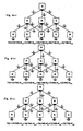
- Figs. 3(a)-(c) the factors for a first-stage filtering process are shown for one pixel consisting of the three light-emitting elements (sub-pixels) of R, G, and B.
- the target sub-pixel is an R sub-pixel
- the sub-pixel to its left is a B sub-pixel
- the sub-pixel to the right is a G sub-pixel
- energy collection is performed so that, for example, a factor of 1/10 is allocated from the B sub-pixel to the left (one sub-pixel prior to the target sub-pixel, n - 1), 3/10 is allocated from the R sub-pixel, which is the target sub-pixel, and 6/10 is allocated from the G sub-pixel to the right (one sub-pixel after the target sub-pixel, n + 1).
- V(n) (1/10) * V n-1 + (3/10) * V n + (6/10) * V n+1 .
- the filtering process when the target sub-pixel is a G sub-pixel is shown in Fig. 3(b) .
- the filtering process when the target sub-pixel is a B sub-pixel is shown in Fig. 3(c) .
- the factors for a second-stage filtering process are described with reference to Figs. 4(a)-(c) .
- the first stage is exactly the same as that shown in Figs. 3(a)-(c) .
- the target sub-pixel is R
- the order of sub-pixels in the stage below the B sub-pixel that branches from the target sub-pixel is GBR as shown in Fig. 4(a)
- energy collection is performed by allocating factors of 6/10, 1/10, and 3/10 in that order from the left side.
- the hierarchy shown in Fig. 4(a) is formed.
- the R sub-pixel (noted sub-pixel, n) at the center of Fig. 4(a)
- V(n) (6/100)* V n-2 + (4/100) * V n-1 + (30/100)* V n + (54/100) *V n+1 + (6/100) * V n+2 .
- the filtering process when the target sub-pixel is a G sub-pixel is as shown in Fig. 4(b) .
- the filtering process when the target sub-pixel is a B sub-pixel is as shown in Fig. 4(c) .
- step 1 the display information indicating that display reduction is to be performed is input to input means 1.
- the reduction rate (n) is then input from input means 1 (step 2).
- step 3 display control means 2 takes the original image data from original image data storage means 4, magnifies or reduces this image by 3/n in the first direction, reduces the original image by 1/n in the second direction, and stores the resulting image in working image data storage means 5.
- Either direction vertical/horizontal may be selected as the first direction of reduction.
- step 4 display control means 2 instructs filtering process means 7 to perform a filtering process, using the factors that reflect the degrees of contribution to luminance, on the working image in working image data storage means 5.
- the factors shown in any of Figs. 3(a)-(c) to 6(a)-(c) may be used.
- filtering process means 5 returns the processed image data to display control means 2.
- Display control means 2 stores the received data in display image storage means 8.
- the storage in display image storage means 8 is not in one pixel units but in units of the three light-emitting elements of R, G, and B that comprise one pixel (that is as a sub-pixel image).
- display control means 2 issues an instruction to anti-aliasing process means 6 to perform smoothing in the second direction of the sub-pixel image, stored in display image storage means 8.
- step 7 display control means 2 instructs display device 3 to display the image (in the form of sub-pixel display) by allocating the three-times magnified/reduced pattern to the three light-emitting elements that comprise one pixel of display device 3 based on the display image stored in display image storage means 8.
- FIG. 7(a)-(e) An example of image reduction by the present embodiment will now be described with reference to Figs. 7(a)-(e) .
- image reduction is performed under the same conditions (by 1 ⁇ 2 in the vertical and horizontal directions) as those of the prior-art example shown in Fig. 8 .
- the first direction is the horizontal direction of Fig. 8 and the second direction is the vertical direction of Fig. 8 .
- the original image is that shown in Fig. 7(a) .
- the original image data for this image are stored in original image data storage means 4.
- Image control means 2 then reduces this image by 1 ⁇ 2 in the vertical direction and magnifies this image by 3/2 in the horizontal direction as shown in Fig. 7(d) and stores the resulting image in working image data storage means 5.
- display control means 2 performs allocation of the working image data of Fig. 7(d) in a manner suitable for sub-pixel mapping and stores the image data of Fig. 7(e) in display image storage means 8. Display reduction, based on a reduced image of sub-pixels, each of which comprises one-third of one pixel, in the first direction (the horizontal direction in this example) is thus performed.
- the loss of information is limited during display reduction and a reduced display that is easy to view is realized.
- the filtering factors are arranged to perform high quality display with minimum color irregularities.
- R, G and B red, green and blue
- the invention should be seen by one skilled in the art to include any combination of color emitters.
- the above specification recites the common primary colors of R, G and B colors.
Description
- This invention concerns a method of performing display reduction of 1/n with a display device having an array of light-emitting elements of the three primary colors of R, G, and B.
- Display equipment that employs various types of display devices has been used in the past. Included among such display devices are color LCD's, color plasma displays, and other display devices, which use three light-emitting elements, respectively emitting light of the three primary colors of R, G, and B. Triads of the three emitters are aligned in a fixed pattern to form one pixel. The pixels are conventionally aligned in a first direction to form one line. A plurality of such lines are aligned in a second direction, orthogonal to the first direction, to complete the display screen.
- The problem that arises in the case where a display reduction of 1/n is to be performed using such a display device will now be described based on the example shown in
Figs. 8(a)-8(d) . This example concerns a display reduction of ½ in the vertical and horizontal directions. - If the original image is as shown in
Fig. 8(a) , the image that is reduced by ½ in the horizontal direction is as shown inFig. 8(b) . When the image is further reduced by ½ in the vertical direction, the image is as shown inFig. 8(c) . - An accurate reduction of the original image by ½ should result in the image shown in
Fig. 8(d) . However, in actuality, the reduced image is as shown inFig. 8(c) . The white portion at the right side of the column, which was contained in the original image, is lost in the reduction process. -
WO-A-00/21066 - Thus with the prior art, there is the problem that when display reduction is performed, part of the information in the original image is lost and the display becomes unclear.
- There is a requirement therefore for a display reduction method in which the loss of information is small.
- The present invention provides a display reduction method for reducing dimensions of an image by a factor of 1/n where n is not equal to zero, the image being displayed on a display device, the display reduction method comprising:
- storing an original image data consisting of a plurality of pixels arranged in an array with a first direction and a second direction, each of the plurality of pixels having three light-emitting elements emitting first, second and third colour;
- forming a working image data by multiplying the original image data by a factor of 3/n in the first direction; and,
- allocating a per-pixel image data of the working image data to the three light-emitting elements, thereby displaying the working image data on the display device.
- By this arrangement, the loss of information in the first direction is limited by making use of the correspondence of three light-emitting elements to one pixel in regard to the first direction. As a result, a display that is clear and easy to view is obtained even after reduction.
- In preferred embodiments, the abovementioned working image data are subject to a filtering process, based on factors that are weighed by the degrees of contribution to luminance of the three primary colors, R, G, and B, prior to making the display device perform the display.
- Since this arrangement takes into account the degrees of contribution of luminance of the three primary colors R, G, and B, sub-pixel display is performed and color irregularities are restricted further in comparison to the prior art to improve the quality of the sub-pixel display.
- Preferably, the filtering process is performed in one stage.
- Since this arrangement takes into account the degrees of contribution of luminance of the three primary colors R, G, and B, color irregularities are limited adequately even by a single-stage filtering process. Moreover, the processing speed is improved by the simplicity of the process.
- In other preferred emobidments, the filtering process is performed in two stages.
- With this arrangement, the degrees of contribution of luminance of the three primary colors R, G, and B, are taken into account over two stages to enable a fine-tuned filtering process to be performed. Color irregularities are thus further limited, thereby enabling further improvement of the display quality.
- Preferably, at least part of the factors are set so that R : G : B = 3 : 6 : 1.
- By this arrangement, luminance adjustment is performed in a manner that matches the actual circumstances.
- Preferably, the filtering process is performed on a total of three sub-pixels centered about a target sub-pixel.
- With this arrangement, since the degrees of contribution of luminance of the three primary colors R, G, and B, are taken into account, color irregularities are limited adequately even by a filtering process performed on a total of three sub-pixels. Moreover, the processing speed is improved by the simplicity of the process.
- In other preferred embodiments, the filtering process is performed on a total of five sub-pixels centered about a target sub-pixel.
- With this arrangement, since the degrees of contribution of luminance of the three primary colors R, G, and B, are taken into account across a wide range and a fine-tuned filtering process is performed, color irregularities are limited further to enable further improvement in the display quality.
- Preferably, an anti-aliasing process is performed in the second direction, after the filtering process and prior to making the display device perform the display.
- With this arrangement, jaggedness of the image is made less conspicuous.
- In preferred embodiments, the working image data are prepared by magnifying or reducing the original image data by 3/n in the first direction and 1/n in the second direction.
- By this arrangement, display reduction of equal rates of reduction in the vertical and horizontal directions is realized with little loss of information.
- Various embodiments of the invention will now be more particularly described by way of example, with reference to the accompanying drawings, in which:
-
Fig. 1 is a block diagram of the display equipment according to an embodiment of this invention; -
Fig. 2 is a flowchart to which reference will be made for explaining the display equipment of an embodiment of this invention; -
Figs. 3(a), (b), and (c) are explanatory diagrams used in explaining the factors used in an embodiment of this invention; -
Figs. 4(a), (b), and (c) are explanatory diagrams used in explaining the factors used in an embodiment of this invention -
Figs. 5(a), (b), and (c) are explanatory diagrams concerning the factors used in an embodiment of this invention; -
Figs. 6(a), (b), and (c) are explanatory diagrams concerning the factors used in an embodiment of this invention. -
Figs. 7(a), (b), (c), (d), and (e) are explanatory diagrams concerning the process of display reduction by an embodiment of this invention; -
Fig. 7(f) is an explanatory diagram of an ideal display reduction; -
Figs. 8(a), (b), and (c) are explanatory diagrams concerning the process of display reduction by a method of the prior art; -
Fig. 8(d) is an explanatory diagram of an ideal display reduction. - Referring to
Fig. 1 , an input means 1 inputs, display information. A display image storage means 8 (VRAM, etc.) contains an image for sub-pixel display. A display control means 2 controls the various elements of the system ofFigure 1 to makedisplay device 3 display the display image stored in the display image storage means 8. -
Display device 3 includes a plurality of sets of three light-emitting elements, which respectively emit light of the three primary colors of R, G, and B. The light-emitting elements are aligned in a fixed order to form one pixel. The pixels are aligned in a first direction to form one line. A plurality of such lines are aligned in a second direction, which is orthogonal to the first direction, to form the display screen. To be more specific,display device 3 may be a color LCD or color plasma display, etc. driven by a driver (not shown) to drive the respective elements of the color LCD or color plasma display, etc. - An original image storage means 4 stores the original image data prior to display reduction. The original image data are raster image data or vector image data that are subsequently developed into raster image data. The original image data may be that of a general image or a font.
- In the process of display reduction by display control means 2, a working image data storage means 5 stores a temporary working image, obtained by magnification or reduction of the original image stored in original image data storage means 4.
- An anti-aliasing process means 6 performs smoothing of the outlines of a given image.
- A filtering process means 7 performs a filtering process, based on factors to be described below, on the working image data stored in working image data storage means 5 and stores the resulting image in display image storage means 8.
- Referring now to
Figs. 3(a)-(c) , the factors for a first-stage filtering process are shown for one pixel consisting of the three light-emitting elements (sub-pixels) of R, G, and B. The degrees of contribution to luminance of the sub-pixels are such that R : G : B = 3 : 6 : 1. - If as shown in
Fig. 3(a) , the target sub-pixel is an R sub-pixel, since the sub-pixel to its left is a B sub-pixel and the sub-pixel to the right is a G sub-pixel, energy collection is performed so that, for example, a factor of 1/10 is allocated from the B sub-pixel to the left (one sub-pixel prior to the target sub-pixel, n - 1), 3/10 is allocated from the R sub-pixel, which is the target sub-pixel, and 6/10 is allocated from the G sub-pixel to the right (one sub-pixel after the target sub-pixel, n + 1). - Thus if the respective sub-pixel values V are expressed using a suffix, the value V(n) after the degrees of contribution to luminance are taken into account is such that V(n) = (1/10) * Vn-1 + (3/10) * Vn + (6/10) * Vn+1.
- Likewise, the filtering process when the target sub-pixel is a G sub-pixel is shown in
Fig. 3(b) . The filtering process when the target sub-pixel is a B sub-pixel is shown inFig. 3(c) . - As can be seen from
Figs. 3(a)-(c) , if just the factors of the first stage are used, the factors are applied to a total of three sub-pixels centered about the target sub-pixel. - The factors for a second-stage filtering process are described with reference to
Figs. 4(a)-(c) . The first stage is exactly the same as that shown inFigs. 3(a)-(c) . Here, when the target sub-pixel is R, since the order of sub-pixels in the stage below the B sub-pixel that branches from the target sub-pixel is GBR as shown inFig. 4(a) , energy collection is performed by allocating factors of 6/10, 1/10, and 3/10 in that order from the left side. - Likewise, since the order of sub-pixels in the stage below the R sub-pixel that branches from the target sub-pixel is BRG, energy collection is performed by allocating factors of 1/10, 3/10, and 6/10 in that order from the left side. Also, for the G sub-pixel that branches from the target sub-pixel, since the order of sub-pixels in the stage below is RGB, energy collection is performed by allocating factors of 3/10, 6/10, and 1/10 in that order from the left side.
- As a result, the hierarchy shown in
Fig. 4(a) is formed. With regard to the R sub-pixel (noted sub-pixel, n) at the center ofFig. 4(a) , there are three pathways, passing through the B, R, and G sub-pixels, respectively, of the upper stage that lead to this target sub-pixel. The factor for the value V(n) of the target sub-pixel is (1/10) * (3/10) + (3/10)* (3/10) + (6/10) * (3/10) = 30/100. - The factor for the other sub-pixels for the lowermost stage are determined in the same manner so that the value V(n) after the degrees of contribution to luminance are taken into account is such that V(n) = (6/100)* Vn-2 + (4/100) * Vn-1 + (30/100)* Vn + (54/100) *Vn+1 + (6/100) * Vn+2.
- Likewise, the filtering process when the target sub-pixel is a G sub-pixel is as shown in
Fig. 4(b) . The filtering process when the target sub-pixel is a B sub-pixel is as shown inFig. 4(c) . - As is clear from
Figs. 4(a)-(c) , when factors of two stages are used, the factors are applied to a total of five sub-pixels centered about the target sub-pixel. - As examples of modifications of the above, those shown in
Figs. 5(a)-(c) (where equal factors of (1/3) are allocated to the second stage) and inFigs. 6(a)-(c) (where equal factors of (1/3) are allocated to the first stage) is given. Even when equal allocation is performed on part of the stages as in these examples, if factors that reflect the degrees of contribution to luminance are used in the other stages, this is adequate for practical purposes in many cases. This invention also includes cases where the above weighting is applied to three or more stages. - Referring now to the flow chart in
Fig. 2 , atstep 1, the display information indicating that display reduction is to be performed is input to input means 1. The reduction rate (n) is then input from input means 1 (step 2). - Then in
step 3, display control means 2 takes the original image data from original image data storage means 4, magnifies or reduces this image by 3/n in the first direction, reduces the original image by 1/n in the second direction, and stores the resulting image in working image data storage means 5. Either direction (vertical/horizontal) may be selected as the first direction of reduction. - Next in step 4, display control means 2 instructs filtering process means 7 to perform a filtering process, using the factors that reflect the degrees of contribution to luminance, on the working image in working image data storage means 5. Here, the factors shown in any of
Figs. 3(a)-(c) to 6(a)-(c) may be used. - When the filtering process is completed, filtering process means 5 returns the processed image data to display control means 2. Display control means 2 stores the received data in display image storage means 8. The storage in display image storage means 8 is not in one pixel units but in units of the three light-emitting elements of R, G, and B that comprise one pixel (that is as a sub-pixel image).
- Next in
step 6, display control means 2 issues an instruction to anti-aliasing process means 6 to perform smoothing in the second direction of the sub-pixel image, stored in display image storage means 8. - Then in
step 7, display control means 2 instructsdisplay device 3 to display the image (in the form of sub-pixel display) by allocating the three-times magnified/reduced pattern to the three light-emitting elements that comprise one pixel ofdisplay device 3 based on the display image stored in display image storage means 8. - An example of image reduction by the present embodiment will now be described with reference to
Figs. 7(a)-(e) . In this example, image reduction is performed under the same conditions (by ½ in the vertical and horizontal directions) as those of the prior-art example shown inFig. 8 . The first direction is the horizontal direction ofFig. 8 and the second direction is the vertical direction ofFig. 8 . - First, the original image is that shown in
Fig. 7(a) . The original image data for this image are stored in original image data storage means 4. Image control means 2 then reduces this image by ½ in the vertical direction and magnifies this image by 3/2 in the horizontal direction as shown inFig. 7(d) and stores the resulting image in working image data storage means 5. - In achieving the condition of
Fig. 7(d) from that ofFig. 7(a) , the condition ofFig. 7(d) is reached via the conditions shown inFigs. 7(b) and 7(c) . - In any case, since the working image data shown in
Fig. 7(d) is stored in working image data storage means 5, display control means 2 performs allocation of the working image data ofFig. 7(d) in a manner suitable for sub-pixel mapping and stores the image data ofFig. 7(e) in display image storage means 8. Display reduction, based on a reduced image of sub-pixels, each of which comprises one-third of one pixel, in the first direction (the horizontal direction in this example) is thus performed. - It can be understood that even in comparison to the ideal reduced image shown in
Fig. 7(f) the image reduction by this embodiment results in the good image reduction result shown inFig. 7(e) , with which the white part of the row at the right is not lost. - As has been described above, by this invention, the loss of information is limited during display reduction and a reduced display that is easy to view is realized. Also, the filtering factors are arranged to perform high quality display with minimum color irregularities.
- Although the invention is described above as controlling R, G and B (red, green and blue) emitters, in some situations, other colors may be selected to produce the desired visual impression. Therefore, the invention should be seen by one skilled in the art to include any combination of color emitters. For example, there may be applications in which only two emitters are required to form a pixel. In other cases, more than three color emitters. For purposes of description, however, the above specification recites the common primary colors of R, G and B colors.
- Having described preferred embodiments of the invention with reference to the accompanying drawings, it is to be understood that the invention is not limited to those precise embodiments, and that various changes and modifications may be effected therein by one skilled in the art.
Claims (11)
- A display reduction method for reducing dimensions of an image by a factor of 1/n where n is not equal to zero, the image being displayed on a display device, the display reduction method comprising:storing an original image data consisting of a plurality of pixels arranged in an array with a first direction and a second direction, each of the plurality of pixels having three light-emitting elements emitting first, second and third colour;forming a working image data by multiplying the original image data by a factor of 3/n in the first direction; and,allocating a per-pixel image data of the working image data to the three light-emitting elements, thereby displaying the working image data on the display device.
- A display reduction method as claimed in Claim 1, further comprising:filtering the working image data; and,weighting said filtering in accordance with degree of respective contribution to luminance of the first, second and third colour, before displaying the working image data on the display device.
- A display reduction method as claimed in Claim 2, wherein the first, second and third colour are R, G and B, respectively.
- A display reduction method as claimed in Claim 2 or Claim 3, wherein at least part of the degree of the respective contribution is given by R:G:B = 3:6:1.
- A display reduction method as claimed in any one of Claims 2 to 4, wherein said filtering includes filtering in one stage.
- A display reduction method as claimed in any one of Claims 2 to 4, where said filtering includes filtering in at least two stages.
- A display reduction method as claimed in any one of Claims 2 to 6, wherein said filtering includes filtering for a total of three sub-pixels centered about a target sub-pixel.
- A display reduction method as claimed in any one of Claims 2 to 6, wherein said filtering includes filtering for five sub-pixels centred about a target sub-pixel.
- A display reduction method as claimed in any one of Claims 2 to 8, further comprising:anti-aliasing in the second direction after said filtering and before displaying the working image data on the display device.
- A display reduction method as claimed in any preceding claim, further comprising:multiplying the original image data by a factor of 1/n in the second direction.
- A display reduction apparatus for reducing dimensions of an image by a factor of 1/n where n is not equal to zero, the image being displayed on a display device (3), the display reduction apparatus comprising:means (4) for storing an original image data consisting of a plurality of pixels arranged in an array with a first direction and a second direction, thereby filling the display device, each of the plurality of pixels having three light-emitting elements emitting first, second and third colour;means (5) for forming a working image data by multiplying the original image data by a factor of 3/n in the first direction; and,means for allocating a per-pixel image data of the working image data to the three light-emitting elements, thereby displaying the working image data on the display device.
Applications Claiming Priority (2)
| Application Number | Priority Date | Filing Date | Title |
|---|---|---|---|
| JP2000220042 | 2000-07-21 | ||
| JP2000220042A JP2002040985A (en) | 2000-07-21 | 2000-07-21 | Reduced display method |
Publications (3)
| Publication Number | Publication Date |
|---|---|
| EP1174823A2 EP1174823A2 (en) | 2002-01-23 |
| EP1174823A3 EP1174823A3 (en) | 2003-01-22 |
| EP1174823B1 true EP1174823B1 (en) | 2008-04-23 |
Family
ID=18714721
Family Applications (1)
| Application Number | Title | Priority Date | Filing Date |
|---|---|---|---|
| EP01306274A Expired - Lifetime EP1174823B1 (en) | 2000-07-21 | 2001-07-20 | Method for image scaling |
Country Status (6)
| Country | Link |
|---|---|
| US (1) | US20020009237A1 (en) |
| EP (1) | EP1174823B1 (en) |
| JP (1) | JP2002040985A (en) |
| KR (1) | KR20020008768A (en) |
| CN (1) | CN1184606C (en) |
| DE (1) | DE60133692T2 (en) |
Families Citing this family (9)
| Publication number | Priority date | Publication date | Assignee | Title |
|---|---|---|---|---|
| JP4442392B2 (en) | 2004-11-05 | 2010-03-31 | カシオ計算機株式会社 | Image processing apparatus and image processing method |
| JP4623290B2 (en) * | 2005-07-01 | 2011-02-02 | 富士ゼロックス株式会社 | Image processing apparatus, image processing method, image processing program, and storage medium |
| KR100657343B1 (en) * | 2005-10-19 | 2006-12-14 | 삼성전자주식회사 | Apparatus and method for processing image |
| US8055077B2 (en) * | 2005-12-02 | 2011-11-08 | Tektronix, Inc. | R/T display compression preserving intensity information |
| US7460133B2 (en) | 2006-04-04 | 2008-12-02 | Sharp Laboratories Of America, Inc. | Optimal hiding for defective subpixels |
| CN102737617B (en) * | 2011-04-01 | 2014-04-30 | 华为终端有限公司 | Method and device for video image display |
| CN103366343B (en) * | 2013-07-17 | 2016-05-04 | 广东欧珀移动通信有限公司 | A kind of bitmap Zoom method and system |
| CN110785804A (en) * | 2017-06-27 | 2020-02-11 | 株式会社半导体能源研究所 | Display system and data processing method |
| DE112018004715T5 (en) | 2017-08-25 | 2020-06-18 | Semiconductor Energy Laboratory Co., Ltd. | Display panel and display device |
Family Cites Families (41)
| Publication number | Priority date | Publication date | Assignee | Title |
|---|---|---|---|---|
| US4720745A (en) * | 1983-06-22 | 1988-01-19 | Digivision, Inc. | Method and apparatus for enhancing video displays |
| EP0151846B1 (en) * | 1984-02-15 | 1987-10-14 | International Business Machines Corporation | Colour display apparatus and method of coding a colour image |
| US5164825A (en) * | 1987-03-30 | 1992-11-17 | Canon Kabushiki Kaisha | Image processing method and apparatus for mosaic or similar processing therefor |
| US5543819A (en) * | 1988-07-21 | 1996-08-06 | Proxima Corporation | High resolution display system and method of using same |
| JP2756292B2 (en) * | 1989-02-07 | 1998-05-25 | キヤノン株式会社 | Document output device |
| JPH03201788A (en) * | 1989-12-28 | 1991-09-03 | Nippon Philips Kk | Color display device |
| GB2263038B (en) * | 1991-12-30 | 1996-01-31 | Apple Computer | Apparatus for manipulating streams of data |
| US5450208A (en) * | 1992-11-30 | 1995-09-12 | Matsushita Electric Industrial Co., Ltd. | Image processing method and image processing apparatus |
| US5796409A (en) * | 1993-04-06 | 1998-08-18 | Ecole Polytechnique Federale De Lausanne | Method for producing contrast-controlled grayscale characters |
| US5633654A (en) * | 1993-11-12 | 1997-05-27 | Intel Corporation | Computer-implemented process and computer system for raster displaying video data using foreground and background commands |
| US5623593A (en) * | 1994-06-27 | 1997-04-22 | Macromedia, Inc. | System and method for automatically spacing characters |
| US6243055B1 (en) * | 1994-10-25 | 2001-06-05 | James L. Fergason | Optical display system and method with optical shifting of pixel position including conversion of pixel layout to form delta to stripe pattern by time base multiplexing |
| US5790714A (en) * | 1994-11-01 | 1998-08-04 | International Business Machines Corporation | System and method for scaling video |
| JP2726631B2 (en) * | 1994-12-14 | 1998-03-11 | インターナショナル・ビジネス・マシーンズ・コーポレイション | LCD display method |
| US5748178A (en) * | 1995-07-18 | 1998-05-05 | Sybase, Inc. | Digital video system and methods for efficient rendering of superimposed vector graphics |
| US6005582A (en) * | 1995-08-04 | 1999-12-21 | Microsoft Corporation | Method and system for texture mapping images with anisotropic filtering |
| US5852443A (en) * | 1995-08-04 | 1998-12-22 | Microsoft Corporation | Method and system for memory decomposition in a graphics rendering system |
| KR100424755B1 (en) * | 1995-09-29 | 2004-08-30 | 마쯔시다덴기산교 가부시키가이샤 | Television receiver |
| US5910805A (en) * | 1996-01-11 | 1999-06-08 | Oclc Online Computer Library Center | Method for displaying bitmap derived text at a display having limited pixel-to-pixel spacing resolution |
| JP3227086B2 (en) * | 1996-02-01 | 2001-11-12 | 基弘 栗須 | TV on-screen display device |
| US5852673A (en) * | 1996-03-27 | 1998-12-22 | Chroma Graphics, Inc. | Method for general image manipulation and composition |
| IL119259A (en) * | 1996-09-17 | 2000-12-06 | Comview Graphics Ltd | Electro-optical display apparatus and method of using same |
| US6288703B1 (en) * | 1996-11-25 | 2001-09-11 | Ultimatte Corporation | Method for removing from an image the background surrounding a selected subject by generating candidate mattes |
| US5990380A (en) * | 1997-10-10 | 1999-11-23 | University Of Florida Research Foundation, Inc. | Percutaneous biofixed medical implants |
| JP3933278B2 (en) * | 1997-11-04 | 2007-06-20 | 株式会社ワコム | Position detecting method and apparatus capable of detecting position indicator |
| US6104375A (en) * | 1997-11-07 | 2000-08-15 | Datascope Investment Corp. | Method and device for enhancing the resolution of color flat panel displays and cathode ray tube displays |
| US6836571B1 (en) * | 1997-11-28 | 2004-12-28 | OCé PRINTING SYSTEMS GMBH | Method for converting digital raster data of a first resolution into digital target data of a second resolution |
| US6348929B1 (en) * | 1998-01-16 | 2002-02-19 | Intel Corporation | Scaling algorithm and architecture for integer scaling in video |
| US6456745B1 (en) * | 1998-09-16 | 2002-09-24 | Push Entertaiment Inc. | Method and apparatus for re-sizing and zooming images by operating directly on their digital transforms |
| ATE511688T1 (en) * | 1998-10-07 | 2011-06-15 | Microsoft Corp | ASSIGNMENT OF IMAGE DATA SAMPLES TO IMAGE DOT SUB-COMPONENTS ON A DISPLAY DEVICE DIVIDED INTO STRIPS |
| US6356278B1 (en) * | 1998-10-07 | 2002-03-12 | Microsoft Corporation | Methods and systems for asymmeteric supersampling rasterization of image data |
| US6278434B1 (en) * | 1998-10-07 | 2001-08-21 | Microsoft Corporation | Non-square scaling of image data to be mapped to pixel sub-components |
| US6377273B1 (en) * | 1998-11-04 | 2002-04-23 | Industrial Technology Research Institute | Fast area-coverage computing method for anti-aliasing in graphics |
| US6750875B1 (en) * | 1999-02-01 | 2004-06-15 | Microsoft Corporation | Compression of image data associated with two-dimensional arrays of pixel sub-components |
| KR100324879B1 (en) * | 1999-02-01 | 2002-02-28 | 마찌다 가쯔히꼬 | Character display apparatus, character display method, and recording medium |
| US6681053B1 (en) * | 1999-08-05 | 2004-01-20 | Matsushita Electric Industrial Co., Ltd. | Method and apparatus for improving the definition of black and white text and graphics on a color matrix digital display device |
| US6563502B1 (en) * | 1999-08-19 | 2003-05-13 | Adobe Systems Incorporated | Device dependent rendering |
| US6384839B1 (en) * | 1999-09-21 | 2002-05-07 | Agfa Monotype Corporation | Method and apparatus for rendering sub-pixel anti-aliased graphics on stripe topology color displays |
| US6775420B2 (en) * | 2000-06-12 | 2004-08-10 | Sharp Laboratories Of America, Inc. | Methods and systems for improving display resolution using sub-pixel sampling and visual error compensation |
| US6608632B2 (en) * | 2000-06-12 | 2003-08-19 | Sharp Laboratories Of America, Inc. | Methods and systems for improving display resolution in images using sub-pixel sampling and visual error filtering |
| KR20020008040A (en) * | 2000-07-18 | 2002-01-29 | 마츠시타 덴끼 산교 가부시키가이샤 | Display apparatus, display method, and recording medium which the display control program is recorded |
-
2000
- 2000-07-21 JP JP2000220042A patent/JP2002040985A/en active Pending
-
2001
- 2001-07-04 CN CNB011224126A patent/CN1184606C/en not_active Expired - Fee Related
- 2001-07-16 US US09/906,359 patent/US20020009237A1/en not_active Abandoned
- 2001-07-20 EP EP01306274A patent/EP1174823B1/en not_active Expired - Lifetime
- 2001-07-20 KR KR1020010043660A patent/KR20020008768A/en not_active Application Discontinuation
- 2001-07-20 DE DE60133692T patent/DE60133692T2/en not_active Expired - Fee Related
Also Published As
| Publication number | Publication date |
|---|---|
| DE60133692T2 (en) | 2009-07-02 |
| EP1174823A2 (en) | 2002-01-23 |
| JP2002040985A (en) | 2002-02-08 |
| EP1174823A3 (en) | 2003-01-22 |
| US20020009237A1 (en) | 2002-01-24 |
| CN1334554A (en) | 2002-02-06 |
| CN1184606C (en) | 2005-01-12 |
| DE60133692D1 (en) | 2008-06-05 |
| KR20020008768A (en) | 2002-01-31 |
Similar Documents
| Publication | Publication Date | Title |
|---|---|---|
| CA1328514C (en) | Method and apparatus for displaying a multicolor image | |
| US8860642B2 (en) | Display and weighted dot rendering method | |
| EP0210423B1 (en) | Color image display system | |
| EP1174854B1 (en) | Display equipment, display method, and storage medium storing a display control program using sub-pixels | |
| EP1174855A2 (en) | Display method by using sub-pixels | |
| EP0396956B1 (en) | Display system for instruments | |
| JP2003520980A (en) | Method and apparatus for efficiently implementing and modifying foreground and background color selection | |
| WO1993013489A1 (en) | An anti-aliasing method for polynomial curves using integer arithmetics | |
| CN104794998A (en) | Display drive method, device and display device | |
| EP1174823B1 (en) | Method for image scaling | |
| WO2011129376A1 (en) | Liquid crystal display device and method for displaying fonts on liquid crystal display device | |
| CN110599962A (en) | Rendering method of Delta type sub-pixel display panel with different color sequences | |
| US7142219B2 (en) | Display method and display apparatus | |
| US7528814B2 (en) | Method and device providing enhanced characters | |
| US20100123721A1 (en) | Image device and data processing system | |
| US6836271B2 (en) | Boldfaced character-displaying method and display equipment employing the boldfaced character-displaying method | |
| EP1557813B1 (en) | Compression of image data associated with two-dimensional arrays of pixel sub-components | |
| EP0403081B1 (en) | Colour display | |
| CN115588409A (en) | Sub-pixel rendering method and device and display equipment | |
| JP2761540B2 (en) | Method and apparatus for displaying an image on a hardware screen | |
| JP4075998B2 (en) | Image display device and image display method | |
| US6388647B2 (en) | Increasing the number of colors output by a passive liquid crystal display | |
| EP1308923A1 (en) | Method and device providing enhanced characters | |
| EP0413483A2 (en) | A display system | |
| JP3089356B2 (en) | Beam forming device for matrix display device |
Legal Events
| Date | Code | Title | Description |
|---|---|---|---|
| PUAI | Public reference made under article 153(3) epc to a published international application that has entered the european phase |
Free format text: ORIGINAL CODE: 0009012 |
|
| AK | Designated contracting states |
Kind code of ref document: A2 Designated state(s): AT BE CH CY DE DK ES FI FR GB GR IE IT LI LU MC NL PT SE TR |
|
| AX | Request for extension of the european patent |
Free format text: AL;LT;LV;MK;RO;SI |
|
| PUAL | Search report despatched |
Free format text: ORIGINAL CODE: 0009013 |
|
| AK | Designated contracting states |
Kind code of ref document: A3 Designated state(s): AT BE CH CY DE DK ES FI FR GB GR IE IT LI LU MC NL PT SE TR |
|
| AX | Request for extension of the european patent |
Free format text: AL;LT;LV;MK;RO;SI |
|
| 17P | Request for examination filed |
Effective date: 20030428 |
|
| AKX | Designation fees paid |
Designated state(s): DE FR GB SE |
|
| 17Q | First examination report despatched |
Effective date: 20050419 |
|
| GRAP | Despatch of communication of intention to grant a patent |
Free format text: ORIGINAL CODE: EPIDOSNIGR1 |
|
| GRAS | Grant fee paid |
Free format text: ORIGINAL CODE: EPIDOSNIGR3 |
|
| GRAA | (expected) grant |
Free format text: ORIGINAL CODE: 0009210 |
|
| AK | Designated contracting states |
Kind code of ref document: B1 Designated state(s): DE FR GB SE |
|
| REG | Reference to a national code |
Ref country code: GB Ref legal event code: FG4D |
|
| REF | Corresponds to: |
Ref document number: 60133692 Country of ref document: DE Date of ref document: 20080605 Kind code of ref document: P |
|
| RAP2 | Party data changed (patent owner data changed or rights of a patent transferred) |
Owner name: PANASONIC CORPORATION |
|
| PG25 | Lapsed in a contracting state [announced via postgrant information from national office to epo] |
Ref country code: SE Free format text: LAPSE BECAUSE OF FAILURE TO SUBMIT A TRANSLATION OF THE DESCRIPTION OR TO PAY THE FEE WITHIN THE PRESCRIBED TIME-LIMIT Effective date: 20080723 |
|
| ET | Fr: translation filed | ||
| PLBE | No opposition filed within time limit |
Free format text: ORIGINAL CODE: 0009261 |
|
| STAA | Information on the status of an ep patent application or granted ep patent |
Free format text: STATUS: NO OPPOSITION FILED WITHIN TIME LIMIT |
|
| 26N | No opposition filed |
Effective date: 20090126 |
|
| PGFP | Annual fee paid to national office [announced via postgrant information from national office to epo] |
Ref country code: FR Payment date: 20090710 Year of fee payment: 9 |
|
| PGFP | Annual fee paid to national office [announced via postgrant information from national office to epo] |
Ref country code: DE Payment date: 20080926 Year of fee payment: 9 Ref country code: GB Payment date: 20090715 Year of fee payment: 9 |
|
| GBPC | Gb: european patent ceased through non-payment of renewal fee |
Effective date: 20100720 |
|
| REG | Reference to a national code |
Ref country code: FR Ref legal event code: ST Effective date: 20110331 |
|
| PG25 | Lapsed in a contracting state [announced via postgrant information from national office to epo] |
Ref country code: DE Free format text: LAPSE BECAUSE OF NON-PAYMENT OF DUE FEES Effective date: 20110201 |
|
| REG | Reference to a national code |
Ref country code: DE Ref legal event code: R119 Ref document number: 60133692 Country of ref document: DE Effective date: 20110201 |
|
| PG25 | Lapsed in a contracting state [announced via postgrant information from national office to epo] |
Ref country code: FR Free format text: LAPSE BECAUSE OF NON-PAYMENT OF DUE FEES Effective date: 20100802 |
|
| PG25 | Lapsed in a contracting state [announced via postgrant information from national office to epo] |
Ref country code: GB Free format text: LAPSE BECAUSE OF NON-PAYMENT OF DUE FEES Effective date: 20100720 |