EP1174746A1 - Optical fiber cable and optical fiber cable with plug - Google Patents
Optical fiber cable and optical fiber cable with plug Download PDFInfo
- Publication number
- EP1174746A1 EP1174746A1 EP00985988A EP00985988A EP1174746A1 EP 1174746 A1 EP1174746 A1 EP 1174746A1 EP 00985988 A EP00985988 A EP 00985988A EP 00985988 A EP00985988 A EP 00985988A EP 1174746 A1 EP1174746 A1 EP 1174746A1
- Authority
- EP
- European Patent Office
- Prior art keywords
- optical fiber
- fiber cable
- coating layer
- adhesive layer
- nylon
- Prior art date
- Legal status (The legal status is an assumption and is not a legal conclusion. Google has not performed a legal analysis and makes no representation as to the accuracy of the status listed.)
- Granted
Links
Images

Classifications
-
- G—PHYSICS
- G02—OPTICS
- G02B—OPTICAL ELEMENTS, SYSTEMS OR APPARATUS
- G02B6/00—Light guides; Structural details of arrangements comprising light guides and other optical elements, e.g. couplings
- G02B6/44—Mechanical structures for providing tensile strength and external protection for fibres, e.g. optical transmission cables
-
- G—PHYSICS
- G02—OPTICS
- G02B—OPTICAL ELEMENTS, SYSTEMS OR APPARATUS
- G02B6/00—Light guides; Structural details of arrangements comprising light guides and other optical elements, e.g. couplings
- G02B6/24—Coupling light guides
- G02B6/36—Mechanical coupling means
- G02B6/38—Mechanical coupling means having fibre to fibre mating means
- G02B6/3807—Dismountable connectors, i.e. comprising plugs
-
- G—PHYSICS
- G02—OPTICS
- G02B—OPTICAL ELEMENTS, SYSTEMS OR APPARATUS
- G02B1/00—Optical elements characterised by the material of which they are made; Optical coatings for optical elements
- G02B1/04—Optical elements characterised by the material of which they are made; Optical coatings for optical elements made of organic materials, e.g. plastics
- G02B1/045—Light guides
- G02B1/046—Light guides characterised by the core material
-
- G—PHYSICS
- G02—OPTICS
- G02B—OPTICAL ELEMENTS, SYSTEMS OR APPARATUS
- G02B1/00—Optical elements characterised by the material of which they are made; Optical coatings for optical elements
- G02B1/04—Optical elements characterised by the material of which they are made; Optical coatings for optical elements made of organic materials, e.g. plastics
- G02B1/045—Light guides
- G02B1/048—Light guides characterised by the cladding material
-
- G—PHYSICS
- G02—OPTICS
- G02B—OPTICAL ELEMENTS, SYSTEMS OR APPARATUS
- G02B6/00—Light guides; Structural details of arrangements comprising light guides and other optical elements, e.g. couplings
- G02B6/02—Optical fibres with cladding with or without a coating
- G02B6/02033—Core or cladding made from organic material, e.g. polymeric material
-
- G—PHYSICS
- G02—OPTICS
- G02B—OPTICAL ELEMENTS, SYSTEMS OR APPARATUS
- G02B6/00—Light guides; Structural details of arrangements comprising light guides and other optical elements, e.g. couplings
- G02B6/02—Optical fibres with cladding with or without a coating
- G02B6/02395—Glass optical fibre with a protective coating, e.g. two layer polymer coating deposited directly on a silica cladding surface during fibre manufacture
-
- G—PHYSICS
- G02—OPTICS
- G02B—OPTICAL ELEMENTS, SYSTEMS OR APPARATUS
- G02B6/00—Light guides; Structural details of arrangements comprising light guides and other optical elements, e.g. couplings
- G02B6/44—Mechanical structures for providing tensile strength and external protection for fibres, e.g. optical transmission cables
- G02B6/4401—Optical cables
- G02B6/4429—Means specially adapted for strengthening or protecting the cables
- G02B6/443—Protective covering
-
- G—PHYSICS
- G02—OPTICS
- G02B—OPTICAL ELEMENTS, SYSTEMS OR APPARATUS
- G02B6/00—Light guides; Structural details of arrangements comprising light guides and other optical elements, e.g. couplings
- G02B6/44—Mechanical structures for providing tensile strength and external protection for fibres, e.g. optical transmission cables
- G02B6/4401—Optical cables
- G02B6/4429—Means specially adapted for strengthening or protecting the cables
- G02B6/4436—Heat resistant
-
- G—PHYSICS
- G02—OPTICS
- G02B—OPTICAL ELEMENTS, SYSTEMS OR APPARATUS
- G02B6/00—Light guides; Structural details of arrangements comprising light guides and other optical elements, e.g. couplings
- G02B6/24—Coupling light guides
- G02B6/36—Mechanical coupling means
- G02B6/38—Mechanical coupling means having fibre to fibre mating means
- G02B6/3807—Dismountable connectors, i.e. comprising plugs
- G02B6/381—Dismountable connectors, i.e. comprising plugs of the ferrule type, e.g. fibre ends embedded in ferrules, connecting a pair of fibres
-
- G—PHYSICS
- G02—OPTICS
- G02B—OPTICAL ELEMENTS, SYSTEMS OR APPARATUS
- G02B6/00—Light guides; Structural details of arrangements comprising light guides and other optical elements, e.g. couplings
- G02B6/24—Coupling light guides
- G02B6/36—Mechanical coupling means
- G02B6/38—Mechanical coupling means having fibre to fibre mating means
- G02B6/3807—Dismountable connectors, i.e. comprising plugs
- G02B6/3833—Details of mounting fibres in ferrules; Assembly methods; Manufacture
- G02B6/3855—Details of mounting fibres in ferrules; Assembly methods; Manufacture characterised by the method of anchoring or fixing the fibre within the ferrule
- G02B6/3857—Crimping, i.e. involving plastic deformation
Definitions
- the present invention relates to an optical fiber cable and optical fiber cable with plug used for optical signal transmission lines, computer connection lines for high-speed optical communications, lines around exchanges, lines for factory automated machinery control, data transmission lines for automobiles and other moving vehicles, and optical sensor lines.
- optical fibers are already used practically in short-distance data communications and sensor applications. At such times, the optical fiber is infrequently used alone, but rather is frequently used in the form of an optical fiber cable in which the outside of the optical fiber is protected with a coating layer.
- the coating layer on the end of the cable is frequently peeled to expose the optical fiber and a plug component is attached to the end of the cable so that it is used in the form of an optical fiber cable with plug.
- the coefficients of thermal expansion of each of the materials that compose the optical fiber, coating layer, and plug are different.
- the optical fiber is easy to contract due to relaxation of its orientation during spinning. Accordingly, phenomenon in which the end of the optical fiber protrudes or retracts from the end of the optical fiber cable with plug, namely the phenomenon of pistoning, may occur due to time-based changes or thermal hysteresis and the like of the optical fiber, coating and plug when the optical fiber cable is used.
- the distance between the end of the optical fiber and the light source or light receiving element changes from its initial value resulting in a change in the amount of coupled light, which may cause problems.
- optical fiber cables are used vehicle mounting applications and in factory control equipment wiring applications. Since optical fiber cables used in such applications are exposed to environments in which lubricating oil, engine oil, and other organic solvents are used, they are required to have oil resistance.
- a technology that uses an amide polymer for the coating layer is disclosed in Japanese Unexamined Patent Application, First Publication No. Sho 50-2552, Japanese Unexamined Patent Application, First Publication No. Hei 10-319281, and the like.
- the object of the present invention is to provide an optical fiber cable having superior oil resistance and flame resistance, that is resistant to peeling of the optical fiber and coating layers, and to provide an optical fiber cable with plug that is resistant to the occurrence of pistoning phenomenon.
- the optical fiber may be composed of a core, a sheath formed around the core, and a protective layer formed around the sheath.
- the optical fiber cable of the present invention is an optical fiber cable in which an adhesive layer, a primary layer, and a secondary layer are sequentially formed around the outside of an optical fiber.
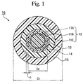
- Fig. 1 is a cross-sectional view showing one mode of optical fiber cable 10 of the present invention.
- Adhesive layer 13 as well as primary coating layer 14 and secondary coating layer 15 are sequentially formed around the outside of optical fiber 12 comprising core 11A, sheath 11B, and protective layer 11C formed on the outside of sheath 11B.
- An optical fiber having a known structure is used for the optical fiber 12, examples of which include an SI optical fiber having a core-sheath structure as shown in Fig. 1, a GI optical fiber in which the refractive index of core 11A gradually decreases from the center to the outside, a multi-layer optical fiber in which the refractive index of core 11A decreases in a stepwise manner from the center to the outside, and a multi-core optical fiber having a plurality of cores 11A in a single optical fiber 12.
- sheath 11B may be additionally coated around the outside of GI optical fibers or multi-layer optical fibers.
- methyl methacrylate polymers are used for the core material, and preferably methyl methacrylate polymers are used. More preferable examples of core materials include methyl methacrylate homopolymers, copolymers having for their main component methyl methacrylate units, copolymers having for their main component benzyl methacrylate units, and fluorinated alkyl methacrylate polymers, with methyl methacrylate homopolymers being particularly preferable.
- sheath material Known materials having a lower refractive index than the core material are used for the sheath material, preferable examples of which include copolymers of fluorinated alkyl (meth)acrylate units and methyl methacrylate units, polymers composed of ⁇ -fluoroacrylic esters, polymers containing a vinylidene fluoride unit, and blends composed of each of the polymers described above.
- a vinylidene fluoride unit preferably vinylidene fluoride unit
- various monomer units such as tetrafluoroethylene, propylene hexafluoride, acetone hexafluoride, ethylene, or propylene
- protective layer 11C refers to a light-transmitting layer that is laminated onto the outermost layer of optical fiber 12 and is able to contribute to the reflective refraction of light when light is transmitted through optical fiber 12. It is preferable that protective layer 11C be fused to core 11A with respect to an optical fiber 12 comprising only an inner layer, namely core 11A, or that protective layer 11C be fused to sheath 11B with respect to an optical fiber 12 having a core-sheath structure when producing optical fiber 12 so that each is substantially integrated into a single unit to tightly adhere the layers.
- Known materials similar to sheath materials are used for the material of protective layer 11C, examples of which include copolymers comprising (meth)acrylates having short-chain fluorinated alkyl groups, (meth)acrylates having long-chain fluorinated alkyl groups and various methyl methacrylate monomer units used in ordinary optical fibers 12 having a high angular aperture, as well as vinylidene fluoride polymers.
- vinylidene fluoride copolymers are used preferably because of the superior flexibility and solvent resistance of optical fiber cable 10.
- vinylidene fluoride polymers that are used preferably include vinylidene fluoride homopolymers as well as copolymers composed of a vinylidene fluoride unit and various monomer units such as tetrafluoroethylene, propylene hexafluoride, acetone hexafluoride, ethylene, or propylene.
- a copolymer composed of vinylidene fluoride units and tetrafluoroethylene units it is preferable that the copolymer contain 70-90 mol% of the vinylidene fluoride unit to increase transparency.
- a light-transmitting material for protective layer 11C that has a smaller refractive index than the material that forms the sheath in order to reduce bending loss of optical fiber 12.
- This optical fiber 12 can be produced by a known method such as the melt spinning method.
- optical fiber cable 10 of the present invention in a high-temperature environment of 70-80°C or in an environment subject to extreme temperature differences, since pistoning is inhibited, it is preferable to use an optical fiber having a small coefficient of thermal contraction for optical fiber 12, and even more preferable to use an optical fiber 12 having a coefficient of contraction of 0 to 0.5% when heated for 50 hours with dry heat at 90°C.
- Such an optical fiber 12 having a small coefficient of thermal contraction can be obtained by, for example, heat treating optical fiber 12.
- this heat treatment can be performed continuously or for each batch, it is preferable to perform heat treatment for each batch for no more than 100 hours at a temperature such that glass transition starting temperature Tg, as measured in accordance with JIS K 7121-1987, of the core of optical fiber 12 and heat treatment temperature T satisfy the equation: Tg - 30 ⁇ T ⁇ Tg.
- optical fiber cable 10 of the present invention adhesive layer 13, primary coating layer 14, and secondary coating layer 15 are sequentially formed around the outside of optical fiber 12.
- adhesive layer 13 refers to a layer provided between optical fiber 12 and primary coating layer 14 that has a thickness of 0.5 to 200 ⁇ m, peel strength between itself and optical fiber 12 of 50 N or more, and peel strength between itself and primary coating layer 14 of 50 N or more.
- peel strength here refers to the force required to peel apart the interface of two layers.
- this adhesive layer 13 since primary layer 14 and optical fiber 12 can be firmly joined even if a material is used for primary coating layer 14 that does not have adequate adhesion with optical fiber 12, the degree of freedom in selecting the material used for primary coating layer 14 increases. Moreover, as a result of this, the degree of freedom in selecting the material used for secondary coating layer 15 also increases. Accordingly, by providing this adhesive layer 13, a material, for example, that does not have adequate adhesion with optical fiber 12 but has other superior properties such as superior flame resistance, can be used for primary coating layer 14, thereby making it possible to impart properties such as flame resistance to optical fiber cable 10.
- the thickness of adhesive layer 13 is less than 0.5 ⁇ m, optical fiber 12 and primary coating layer 14 can no longer be firmly joined, while if the thickness of adhesive layer 13 exceeds 200 ⁇ m, various properties such as flame resistance and solvent resistance of optical fiber cable 10 decrease, it also increases the cost of the material used for adhesive layer 13. In addition, in the case of a layer having a peel strength of less than 50 N, optical fiber 12 and primary coating layer 14 cannot be firmly joined.
- a material containing a polyamide polymer is preferably used for this adhesive layer 13. If a polyamide polymer is used, and particularly in the case primary coating layer 14 is formed from a material having for its main component a polyamide polymer, the peel strength between adhesive layer 13 and primary coating layer 14 can be further increased.
- polyamide polymers include homopolymers composed of monomer units such as nylon 10, nylon 11, nylon 12, nylon 6, and nylon 66, copolymers composed of combinations of these monomer units, and nylon elastomers which are copolymers containing nylon monomer units containing flexible segments. These may be used alone or in combinations of two or more types, and may also be used as a mixture with other polymers and compounds.
- copolymers composed of a nylon 12 unit and at least one nylon 6 unit and nylon 66 unit, mixtures of polyamide polymer and vinylidene fluoride polymer, nylon elastomers and mixtures of polyamide polymer and at least one organic acid and organic acid anhydride are preferable.
- adhesive layer 13 can be formed around the outside of optical fiber 12 at a comparatively low temperature. Accordingly, the use of these polymers is preferable because adhesive layer 13 can be easily formed without causing thermal deterioration of the transmission performance of optical fiber 12.
- materials containing these polymers have superior adhesion with vinylidene fluoride polymers. Accordingly, providing adhesive layer 13 with a material containing these polymers on optical fiber 12 in which the outermost layer is formed from vinylidene fluoride polymer is particularly preferable because it increases the peel strength between optical fiber 12 and adhesive layer 13.
- copolymers composed of a nylon 12 unit and at least one nylon 6 unit or nylon 66 unit have a comparatively large number of amide bonds with polar groups per molecule, interaction occurs with the polarity of the vinylidene fluoride polymer. Accordingly, when a material containing a copolymer composed of a nylon 12 unit and at least one nylon 6 unit and nylon 66 unit is used for adhesive layer 13, the peel strength between adhesive layer 13 and optical fiber 12 and the peel strength 15 between adhesive layer 13 and primary coating layer 14 are both superior. In particular, even more superior peel strength is obtained if a three-dimensional copolymer composed of a nylon 12 unit, nylon 6 unit, and nylon 66 unit is used.
- the content of polyamide polymer in the mixture of polyamide polymer and vinylidene fluoride polymer is preferably 50% by weight or more, and more preferably 95% by weight or less in order to sufficiently improve peel strength.
- nylon elastomers have good flexibility and large elongation. Accordingly, if adhesive layer 13 is provided that is composed of a material containing nylon elastomer, when force is applied to optical fiber cable 10 that causes primary coating layer 14 to peel off stress occurring at the interface of optical fiber 12 and adhesive layer 13 as well as that occurring at the interface of adhesive layer 13 and primary coating layer 14 is alleviated and reduced, thereby peeling strength is substantially increased.
- the mixture of polyamide polymer and at least one of organic acid and organic acid anhydride has high polarity, and in particular, in the case the outermost layer of optical fiber 12 is formed from a vinylidene fluoride polymer, interaction occurs with the polarity of the vinylidene fluoride polymer. Accordingly, adhesive layer 13 is formed that has extremely high peel strength.
- the polyamide copolymer used here is preferably nylon 11 or nylon 12 polymer, and in particular, nylon 11 homopolymer or nylon 12 homopolymer is preferably used.
- organic acids include methacrylic acid, acrylic acid, maleic acid, fumaric acid, salicylic acid, succinic acid, glutaric acid, and phthalic acid.
- organic acid anhydrides include anhydrides of these organic acids.
- the content of at least one of the organic acid and organic acid anhydride relative to 100 parts by weight of polyamide polymer is preferably 0.1 parts by weight or more in order to adequately improve peel strength, and preferably 10 parts by weight or less in order to maintain flexibility of the coating layers and preventing worsening of the handling ease of optical fiber cable 10.
- nylon 11 in particular has superior properties in comparison with nylon 12 in terms of dynamic properties such as low-temperature impact strength, bending fatigue resistance, tensile rupture elongation, and low flexural elasticity, wear resistance, coefficient of linear expansion, and low gas permeability. Consequently, when nylon 11 is used for the polyamide polymer, an optical fiber cable 10 can be obtained that has superior flexibility and fatigue resistance, and low levels of pistoning in high-temperature environments as well as deterioration of transmission characteristics as compared with the case of using nylon 12.
- nylon 11 which has a melting point about 10°C higher than nylon 12
- nylon 11 since nylon 11 has superior bending resistance and wear resistance, even in cases in which optical fiber cable 10 is deformed, dynamic action such as stress applied to optical fiber 12 as well as contraction of optical fiber 12 in high-temperature environments can be further inhibited.
- the outermost layer of optical fiber 12 is formed with a polymer having ester groups or highly polar C-F bonds such as fluorinated (meth)acrylate or vinylidene fluoride
- nylon 11 for the adhesive layer. This is because, since nylon 11 has a larger amount of amide bonds per unit weight than nylon 12, strong interaction occurs between these amide bonds and the polarity of the outermost layer of optical fiber 12, enabling adhesive layer 13 to be formed which firmly joins with optical fiber 12 and primary coating layer 14.
- Primary coating layer 14 is provided on the outside of adhesive layer 13 by strongly adhering with adhesive layer 13 and inhibits pistoning of optical fiber 12, and furthermore, secondary coating layer 15 is provided on the outside of primary coating layer 14 which can be peeled off comparatively easily as necessary such as during connecting work of optical fiber cable 10.
- secondary coating layer 15 is provided on the outside of primary coating layer 14 which can be peeled off comparatively easily as necessary such as during connecting work of optical fiber cable 10.
- a material containing a amide polymer having superior oil resistance, heat resistance and the like is preferably used for primary coating layer 14 and secondary coating layer 15.
- polyamide polymers include homopolymers composed of monomer units such as nylon 11, nylon 12, nylon 6, nylon 66, nylon 612, and nylon 621, polyamide copolymers composed of combinations of these monomer units, and nylon elastomers.
- nylon 11 homopolymers and nylon 12 homopolymers are preferably used because they have satisfactory moldability in the coating process and are unlikely to cause thermal and mechanical damage to optical fiber 12.
- a polyester elastomer may also be used alone for primary coating layer 14 and secondary coating layer 15. Alternatively, this may be used in combination with a polyamide polymer.
- polyester elastomers examples include “HYTREL” (trade name: DU PONT-TORAY CO., LTD.), “PELPRENE” (trade name: Toyobo Co., Ltd.) and “LUMOD” (trade name: General Electric Company).
- the optical fiber cable 10 of the present invention preferably is provided with flame resistance to a degree that passes a flame resistance test in compliance with DIN 72251-5.
- a material consisting of a mixture of 8 to 60 parts by weight of a triazine compound to 100 parts by weight of polyamide polymer for the material that forms primary coating layer 14 or secondary coating layer 15. More preferably, a material is used that consists of a mixture of 10 to 60 parts by weight of triazine compound to 100 parts by weight of polyamide polymer.
- the compound represented with the following chemical formula (1) is one example of that used for the triazine compound, and melamine-cyanuric acid is particularly preferable: (wherein, R represents OH, NH 2 or N(R 1 ) 2 H, and R 1 represents an aliphatic alkyl group).
- additives such as phosphorus compounds, antimony compounds, molding assistants and other typically added additives may be added to the polyamide polymer.
- the flame resistant test to be measured in compliance with DIN 72551-5 refers to that in which the test of DIN 72551-5, which is a method of measuring flame resistance for electrical wires, has been slightly modified in the manner described below in order to measure the flame resistance of optical fiber cable 10.
- this measurement method it is necessary to hold electrical wire at an incline of 45° during or after combustion.
- optical fiber cable 10 differs from electrical wiring in that it is difficult to hold optical fiber cable 10 at an incline of 45° during or after combustion of optical fiber 12. Accordingly, flame resistance is measured while wrapping a pair of copper wires so as to be mutually crossing in the form of a spiral around optical fiber cable 10 in order to hold optical fiber cable 10 at an incline of 45° during or after combustion.
- Copper wire having a diameter of 0.7 mm ⁇ is used for the copper wire, and the spiraling period is 20 mm in the lengthwise direction of optical fiber cable 10.
- a criterion for determining the acceptability of the flame resistance test is such that if the flame goes out within 30 seconds after igniting optical fiber 12 and moving the flame away from the sample, the sample is acceptable, while if the flame does not go out within 30 seconds, the sample is not acceptable.
- the peel strength of primary coating layer 14 and secondary coating layer 15 is 30 N or less, and more preferably from 2.9 to 30 N. If the peel strength is less than 2.9 N, optical fiber 12 with primary coating layer 14 easily comes apart from secondary coating layer 15, thereby tending to make handling difficult. On the other hand, if peel strength exceeds 30 N, stripping becomes poor, and primary coating 14 may stretch when peeling secondary coating layer 15 during connection work of optical fiber cable 10 and the like, thereby resulting in the risk of decreased handling ease.
- the peel strength of secondary coating layer 15 and primary coating layer 14 can be adjusted by suitably selecting the combination of materials used for primary coating layer 15 and materials used for primary coating 14 or by suitably selecting a coating method to be described later.
- primary coating layer 14 and secondary coating layer 15 of optical fiber cable 10 may be composed of a single layer as in the example of Fig. 1, or they may be respectively composed of multiple layers.
- the peel strength between those layers is preferably 50 N or more, and more preferably 58.8 N or more. If the peel strength is less than 50 N, adhesion between layers is insufficient which may prevent the effect of providing adhesive layer 13 from being adequately demonstrated.
- secondary coating layer 15 is composed of multiple layers, there are no particular restrictions on the peel strength between those layers.
- secondary coating layer 15 that is the outermost layer of optical fiber cable 10 of the present invention
- ease of identification and design of optical fiber cable 10 can be easily enhanced.
- a material composed of nylon 11 or nylon 12 that does not contain an additive such as dye for primary coating layer 14 the additive contained in secondary coating layer 15 can be inhibited from migrating to optical fiber 12.
- deterioration of the transmission characteristics of optical fiber 12 caused by migration of this additive into optical fiber 12 can be prevented.
- various dyes and other additives can be selected for improving the ease of identification and design of optical fiber cable 10 while maintaining superior transmission characteristics.
- D 1 /D 2 is 1.2 to 3.5. If D 1 /D 2 is less than 1.2, improvement of the characteristics of optical fiber cable 10 resulting from providing primary coating layer 14 and secondary coating layer 15 are inadequate. For example, even if a material having superior flame resistance is used for primary coating layer 14 and secondary coating layer 15, if D 1 /D 2 is less than 1.2, the flame resistance of optical fiber cable 10 is inadequate. If D 1 /D 2 exceeds 3.5, the flexibility of optical fiber cable 10 decreases resulting in poor handling. Consequently, it is difficult to install optical fiber cable 10 in confined areas, thereby making it unsuitable for automotive applications and the like.
- Optical fiber cable 10 of the present invention can be produced by a known method, examples of which include a method in which adhesive layer 13, primary coating layer 14 and secondary coating layer 15 are sequentially provided on optical fiber 12 using a cross head coating apparatus, and a method in which a material that forms adhesive layer 13, primary coating layer 14 and secondary coating layer 15 is laminated on a material that forms optical fiber 12 by a method of multi-component fiber spinning.
- a method in which adhesive layer 13, primary coating layer 14, and secondary coating layer 15 are sequentially provided on optical fiber 12 using a cross head coating apparatus is preferable.
- a method in which adhesive layer 13 and primary coating layer 14 are collectively coated onto optical fiber 12 followed by coating secondary coating layer 15 is especially preferable.
- the peel strength between adhesive layer 13 and primary coating layer 14 can be controlled to 50 N or more, and furthermore, peel strength between primary coating layer 14 and secondary coating layer 15 can be controlled to 30 N or less.
- peel strength can also be adjusted by the coating apparatus used.
- a cross head coating apparatus of the compression type as shown in Fig. 2 in which the end of nipple 22 is located to the inside of the end surface 21 a of die 21.
- the peel strength between primary coating layer 14 and secondary coating layer 15 can be lowered to 30 N or less, thereby improving the ease of stripping of optical fiber cable 10, the use of a tubing type of coating apparatus is preferable. Furthermore, these coating apparatuses can be suitably used according to the materials composing optical fiber 12, adhesive layer 13, and each of the coating layers as well as the required peel strength.
- a cross head coating apparatus of the compression type in which adhesive layer 13 and primary coating layer 14 are coated collectively as shown in Fig. 2 in order to increase the peel strengths between optical fiber 12 and adhesive layer 13 and between adhesive layer 13 and primary coating layer 14.
- this coating apparatus is equipped with die 21 and nipple 22.
- this apparatus by feeding a material that forms adhesive layer 13 from a first flow path 23, and feeding a material that forms primary coating layer 14 from a second flow path 24, adhesive layer 13 and primary coating layer 14 can be collectively coated around optical fiber 12.
- reference symbol 25 represents the axis of optical fiber 12 that passes through the center of nipple 22.
- the coating temperature is preferably from 200 to 220°C. If the temperature is lower than 200°C, the fluidity of the material is low, and as a result, moldability may decrease and also it leads to the risk of being unable to adequately increasing the peel strength between optical fiber 12 and adhesive layer 13. On the other hand, if the temperature exceeds 220°C, optical fiber 12 may melt and become deformed, and its optical characteristics may be deteriorated.
- the angle ⁇ formed by a third flow path 26, into which first flow path 23 and second flow path 24 merge, and optical fiber axis 25 is preferably from 30 to 60°. Namely, it is preferable that optical fiber 12 and the materials that form adhesive layer 13 and primary coating layer 14 make contact at an angle of 30 to 60°. If ⁇ is smaller than 30°, it is difficult to coat adhesive layer 13 and primary coating layer 14 at a uniform thickness on optical fiber 12, while if ⁇ is larger than 60°, the heat and stress applied to optical fiber 12 by the materials heated to a high temperature increase, which may cause deterioration of the optical characteristics of optical fiber 12. In the case of using nylon 11 or nylon 12 for the polyamide polymer, it is preferable to form third flow path 26 at an angle of 40 to 50° with respect to optical fiber axis 25.
- the coating temperature and contact angle between the materials and optical fiber 12 are also preferably within the above ranges.
- adhesion between optical fiber 12 and adhesive layer 13 can be increased by controlling the thickness of die 21 used (distance to end surface 21a of die 21 from the position where the materials of optical fiber 12 and adhesive layer 13 make contact within the coating apparatus) and the aperture of die 21.
- the thickness of die 21 is preferably 3 to 7 mm, and more preferably 4 to 6 mm.
- the diameter of the aperture of die 21 is preferably from 2.3 to 2.6 mm, and more preferably from 2.35 to 2.5 mm, in the case of producing, for example, an optical fiber cable 10 having a diameter of 2.2 mm.
- the diameter of the aperture of die 21 is preferably about 104 to 118%, and more preferably 107 to 114%, of the diameter of optical fiber cable 10.
- adhesion between optical fiber 12 and adhesive layer 13 can be increased the smaller the diameter of the aperture of die 21, if the diameter of the aperture of die 21 is about equal to the diameter of optical fiber cable 10, the heat and stress applied to optical fiber 12 by the materials heated to a high temperature may cause deterioration of the optical characteristics of optical fiber 12.
- optical fiber cable 10 can be produced having superior adhesion between optical fiber 12 and adhesive layer 13 as well as superior optical characteristics.
- the optical fiber cable with plug of the present invention has a plug connected to at least one end of the above optical fiber cable 10.
- the plug can be selected from known plugs according to the application.
- a fastening (caulking) mechanism for example, can be used as the mechanism for anchoring the plug to optical fiber cable 10. It is preferable that a plug having high mechanical strength be used for the plug.
- test cables inspected The number of test cables inspected and the number of acceptable test cables are shown in the tables.
- a test optical fiber cable 30 was prepared in which the coating on one end is peeled back, the coating on the other end is not peeled back, and the length L of the coated portion is 30 mm.
- Optical fiber cable 10 was immersed for 1000 hours in gasoline at 25°C, and the increase in transmission loss caused by that immersion (dB/km) was measured from the difference between transmission loss of optical fiber cable 10 after immersion and transmission loss of optical fiber cable 10 before immersion.
- Secondary coating layer 15 was separated from optical fiber cable 10 and the status of primary coating layer 14 at the separated portion was assessed visually. Wire stripper separation was judged as being acceptable (indicated with ⁇ in the tables) if there were no abnormalities such as stretching or damage in primary coating layer 14.
- a pistoning test was carried out by peeling off secondary coating layer 15 from the end of optical fiber cable 10 to expose primary coating layer 14, attaching a plug having an inner diameter 50 ⁇ m larger than the diameter of primary coating layer 14 to this end and fastening (caulking) to primary coating layer 14 to form an optical fiber cable with plug having a length of 50 cm. This was then allowed to stand for 1000 hours in an atmosphere at 85°C and 95% relative humidity followed by measurement of the length ( ⁇ m) by which optical fiber 12 later protruded or retracted from the end surface.
- MMA methylmethacrylate
- MAA 1,1,2,2-H-perfluorodecylmethacrylate
- MAA MMA/methacrylic acid
- these materials were melted, sequentially laminated in concentric fashion starting from the center and compound spun to obtain optical fiber 10 having a core diameter of 970 ⁇ m, sheath thickness of 5 ⁇ m and protective layer thickness of 10 ⁇ m.
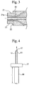
- the same material as primary coating layer 14 was supplied to a cross head coating apparatus using the tubing method as shown in Fig. 3 to form secondary coating layer 15, and optical fiber cable 10 having an outer diameter of 2.2 mm is obtained.
- the coating temperature at this time was 210°C
- the angle ⁇ formed between third flow path 26 and optical fiber axis 25 was 45°
- the thickness of die 21 was 3 mm
- the diameter of the aperture of die 21 was 2.4 mm.
- the transmission loss of the resulting optical fiber cable 10 was satisfactory at 122 dB/km.
- optical fiber cable 10 was measured for flame resistance, peel strength, solvent resistance, wire stripper separation and pistoning.
- the composition of optical fiber cable 10 and the results of these evaluations are shown in Tables 1 and 5.
- optical fiber cables 10 were produced in the same manner as Example 1 followed by measurement of transmission loss, flame resistance, peel strength, solvent resistance, wire stripper separation, and pistoning.
- the compositions of optical fiber cables 10 along with the results of their evaluation are shown in Tables 1 through 8.
- optical fiber used may be composed of a core, a sheath formed around the core, and a protective layer formed around the sheath.
Landscapes
- Physics & Mathematics (AREA)
- General Physics & Mathematics (AREA)
- Optics & Photonics (AREA)
- Optical Fibers, Optical Fiber Cores, And Optical Fiber Bundles (AREA)
Abstract
Description

| Ex. 1 | Ex.2 | Ex.3 | Ex.4 | ||
| Optical fiber | Core | (A) | (A) | (A) | (A) |
| Sheath | (B) | (B) | (B) | (B) | |
| Protective layer | (C) | (C) | (C) | (C) | |
| Outer diam./µm | 1000 | 1000 | 1000 | 1000 | |
| Adhesive layer | Material | Ny12/Ny6/ Ny66 copolymer | Mixture of Ny12 and VDF/TFE copolymer (1) (50:50 weight ratio) | | Mixture of Ny12 and MAA (100: 1.5 weight ratio) |
| Thickness/ µm | 100 | 50 | 50 | 20 | |
| Primary coating layer | Material | Mixture of Ny12 and ICM (100:20 weight ratio) | Mixture of Ny12 and ICM (100:20 weight ratio) | Mixture of Ny12 and ICM (100:20 weight ratio) | Mixture of Ny12 and ICM (100:20 weight ratio) |
| Outer diam./mm | 1.5 | 1.5 | 1.5 | 1.6 | |
| Secondary coating layer | Material | Mixture of Ny12 and ICM (100:20 weight ratio) | Mixture of Ny12 and ICM (100:20 weight ratio) | Mixture of Ny12 and ICM (100:20 weight ratio) | Mixture of Ny12 and ICM (100:20 weight ratio) |
| Outer diam./mm | 2.2 | 2.2 | 2.2 | 2.2 | |
| D1/D2 | 1.83 | 2 | 2 | 2.12 |
| Ex. 5 | Ex. 6 | Comp. Ex. 1 | Comp. Ex. 2 | Comp. Ex. 3 | ||
| Optical fiber | Core | (A) | (A) | (A) | (A) | (A) |
| Sheath | (B) | (B) | (B) | (B) | (B) | |
| Protective layer | (C) | (C) | (C) | (C) | (C) | |
| Outer diam./µm | 1000 | 1000 | 1000 | 1000 | 1000 | |
| Adhesive layer | Material | Copolymer of Ny12/Ny6/ Ny66 | Copolymer of Ny12/Ny6/ Ny66 | Copolymer of Ny12/Ny6/ Ny66 | Copolymer of Ny12/Ny6/ Ny66 | None |
| Thickness/ µm | 50 | 50 | 250 | 150 | - | |
| Primary coating layer | Material | Mixture of Ny12 and ICM (100:10 weight ratio) | Mixture of Ny12 and ICM (100:40 weight ratio) | Mixture of Ny12 and ICM (100:20 weight ratio) | Mixture of Ny12 and ICM (100:20 weight ratio) | Mixture of Ny12 and ICM (100:20 weight ratio) |
| Outer diam./mm | 1.5 | 1.5 | 1.5 | 1.4 | 1.5 | |
| Second-ar y coating layer | Material | Mixture of Ny12 and ICM (100:10 weight ratio) | Mixture of Ny12 and ICM (100:40 weight ratio) | Mixture of Ny12 and ICM (100:20 weight ratio) | Mixture of Ny12 and ICM (100:20 weight ratio) | Mixture of Ny12 and ICM (100:20 weight ratio) |
| Outer diam./mm | 2.2 | 2.2 | 2.2 | 1.5 | 2.2 | |
| D1/D2 | 2 | 2 | 1.47 | 1.15 | 2.2 |
| Ex. 7 | Ex. 8 | Ex. 9 | ||
| Optical fiber | Core | (A) | (A) | (A) |
| Sheath | VDF/TFE copolymer (2) | (C) | (C) | |
| Protective layer | None | VDF/TFE copolymer (2) | None | |
| Outer diameter/µm | 1000 | 1000 | 750 | |
| Adhesive layer | Material | Mixture of Ny12 and copolymer of Ny12/Ny6/ Ny66 (50:50 weight ratio) | Mixture of Ny11 and copolymer of Ny12/Ny6/ Ny66 (80:20 weight ratio) | Mixture of Ny11 and maleic anhydride (98:2 weight ratio) |
| Thickness/µm | 80 | 70 | 100 | |
| Primary coating layer | Material | Ny11 | Mixture of Ny12 and ICM (100:20 weight ratio) | Mixture of Ny11 and ICM (100:20 weight ratio) |
| Outer diameter/mm | 1.5 | 1.6 | 1.4 | |
| Secondary coating layer | Material | Mixture of Ny12 and ICM (100:40 weight ratio) ratio) | Mixture of Ny12 and ICM (100:20 weight ratio) | Mixture of Ny6/Ny12 copolymer and ratio) ICM (100:20 weight ratio) |
| Outer diameter/mm | 2.2 | 2.2 | 1.8 | |
| D1/D2 | 1.9 | 1.9 | 1.9 |
| Ex.10 | Ex.11 | Ex.12 | Ex.13 | ||
| Optical fiber | Core | (A) | (A) | (A) | (A) |
| Sheath | (B) | (D) | VDF/TFE copolymer (2) | (B) | |
| Protective layer | VDF/TFE copolymer (2) | VDF/TFE copolymer (2) | (C) | (C) | |
| Outer diam./µm | 1000 | 1000 | 500 | 1000 | |
| Adhesive layer | Material | Mixture of Ny11 and Ny12/Ny6/ Ny66 copolymer (75:25 weight ratio) | Mixture of Ny11 and Ny12/Ny6/ Ny66 copolymer (90:10 weight ratio) | Ny12/Ny6/ Ny66 copolymer | Ny11 |
| Thickness/ µm | 100 | 100 | 90 | 100 | |
| Primary coating layer | Material | Mixture of Ny12 and ICM (100:20 weight ratio) | Mixture of Ny12 and ICM (100:20 weight ratio) | Mixture of Ny11 and ICM (100:20 weight ratio) | Mixture of Ny12 and ICM (100:20 weight ratio) |
| Outer diam./mm | 1.8 | 1.4 | 1.2 | 1.5 | |
| Secondary coating layer | Material | Mixture of nylon 12 elastomer and ICM (100:20 weight ratio) | Mixture of Ny6/Ny12 copolymer and ICM (100:20 weight ratio) | Mixture of Ny6/Ny12 copolymer and ICM (100:20 weight ratio) | Mixture of Ny12 and ICM (100:20 weight (100:20 weight ratio) |
| Outer diam./mm | 2.2 | 1.5 | 2.2 | 2.2 | |
| D1/D2 | 1.8 | 1.25 | 3.2 | 1.83 |
| Ex. I | Ex.2 | Ex. 3 | Ex.4 | Ex.5 | Ex.6 | |
| Transmiss ion loss (dB/km) | 122 | 125 | 126 | 128 | 123 | 130 |
| Flame resistance (no. acceptable / no. tested) | 20/20 | 20/20 | 20/20 | 20/20 | 20/20 | 20/20 |
| Solvent resistance (dB/km) | 122 | 124 | 125 | 125 | 123 | 128 |
| Peel strength (1)(N) | 80 or more | 80 or more | 80 or more | 80 or more | 80 or more | 80 or more |
| Peel strength (2)(N) | 20 | 20 | 20 | 20 | 20 | 20 |
| WS separation | ○ | ○ | ○ | ○ | ○ | ○ |
| Pistoning (µm) | 0 | 0 | 0 | 0 | 0 | 0 |
| Comp. Ex. 1 | Comp. Ex. 2 | Comp. Ex. 3 | |
| Transmission loss (dB/km) | 123 | 129 | 123 |
| Flame resistance (no. acceptable/ no. tested) | 15/20 | 3/20 | 20/20 |
| Solvent resistance (dB/km) | 124 | 130 | 126 |
| Peel strength (N) | 80 or more | 80 or more | 20 |
| Peel strength (N) | 20 | 20 | 20 |
| WS separation | ○ | ○ | ○ |
| Pistoning (µm) | 0 | 0 | -40 |
| Ex.7 | Ex.8 | Ex.9 | Ex. 10 | Ex.11 | Ex.12 | |
| Transmission loss (dB/km) | 125 | 129 | 128 | 126 | 122 | 135 |
| Flame resistance (no. acceptable/no. tested) | 20/20 | 20/20 | 20/20 | 20/20 | 20/20 | 20/20 |
| Solvent resistance (dB/km) | 125 | 130 | 127 | 127 | 122 | 136 |
| Peel strength (1)(N) | 80 or more | 80 or more | 80 or more | 80 or more | 80 or more | 80 or more |
| WS separation | ○ | ○ | ○ | ○ | ○ | ○ |
| Pistoning (µm) | 0 | 0 | 0 | 0 | 0 | 0 |
| Example 13 | |
| Transmission loss (dB/km) | 125 |
| Flame resistance (no. acceptable/no. tested) | 20/20 |
| Solvent resistance (dB/km) | 124 |
| Peel strength (1) (N) | 80 or more |
| Peel strength (2) (N) | 20 |
| WS separation | ○ |
| Pistoning (µm) | 0 |
Claims (20)
- An optical fiber cable of diameter D1 (mm) in which an adhesive layer having a thickness of 0.5 to 200 µm, a primary coating layer, and a secondary coating layer are sequentially formed around the outside of an optical fiber in which the outermost layer is composed of vinylidene fluoride polymer;
wherein, in the case the diameter of the optical fiber is represented with Da (mm), the thickness of the adhesive layer is represented with d (mm), and Da + 2d is represented with D2, then D1/D2 = 1.2 to 3.5. - An optical fiber cable of diameter D1 (mm) in which an adhesive layer having a thickness of 0.5 to 200 µm, a primary coating layer, and a secondary coating layer are sequentially formed around the outside of an optical fiber composed of a core, a sheath formed around the core, and a protective layer formed around the sheath;
wherein, in the case the diameter of the optical fiber is represented with Da (mm), the thickness of the adhesive layer is represented with d (mm), and Da + 2d is represented with D2, then D1/D2 = 1.2 to 3.5. - The optical fiber cable according to claim 1, wherein the primary coating layer and secondary coating layer are composed of a material containing polyamide polymer.
- The optical fiber cable according to claim 2, wherein the primary coating layer and secondary coating layer are composed of a material containing polyamide polymer.
- The optical fiber cable according to claim 1, being acceptable of a flame resistance test in compliance with DIN 72551-5.
- The optical fiber cable according to claim 2, being acceptable of a flame resistance test in compliance with DIN 72551-5.
- The optical fiber cable according to claim 1, wherein at least one of the primary coating layer and the secondary coating layer is composed of a material in which 8 to 60 parts by weight of triazine compound is mixed with respect to 100 parts by weight of polyamide polymer.
- The optical fiber cable according to claim 2, wherein at least one of the primary coating layer and the secondary coating layer is composed of a material in which 8 to 60 parts by weight of triazine compound is mixed with respect to 100 parts by weight of polyamide polymer.
- The optical fiber cable according to claim 1, wherein the adhesive layer is composed of a material containing a copolymer comprised of a nylon 12 unit and at least one of nylon 6 unit and nylon 66 unit.
- The optical fiber cable according to claim 2, wherein the adhesive layer is composed of a material containing a copolymer comprised of a nylon 12 unit and at least one of nylon 6 unit and nylon 66 unit.
- The optical fiber cable according to claim 1, wherein the adhesive layer is composed of a material containing nylon elastomer.
- The optical fiber cable according to claim 2, wherein the adhesive layer is composed of a material containing nylon elastomer.
- The optical fiber cable according to claim 1, wherein the adhesive layer is composed of a material containing polyamide polymer and vinylidene fluoride polymer.
- The optical fiber cable according to claim 2, wherein the adhesive layer is composed of a material containing polyamide polymer and vinylidene fluoride polymer.
- The optical fiber cable according to claim 1, wherein the adhesive layer is composed of a material containing nylon 12 polymer and at least one of organic acid and organic acid anhydride.
- The optical fiber cable according to claim 2, wherein the adhesive layer is composed of a material containing nylon 12 polymer and at least one of organic acid and organic acid anhydride.
- The optical fiber cable according to claim 1, wherein the adhesive layer is composed of a material containing nylon 11.
- The optical fiber cable according to claim 2, wherein the adhesive layer is composed of a material containing nylon 11.
- An optical fiber cable with plug comprising a plug connected to at least one end of the optical fiber cable according to claim 1.
- An optical fiber cable with plug comprising a plug connected to at least one end of the optical fiber cable according to claim 2.
Applications Claiming Priority (3)
| Application Number | Priority Date | Filing Date | Title |
|---|---|---|---|
| JP37491199 | 1999-12-28 | ||
| JP37491199 | 1999-12-28 | ||
| PCT/JP2000/009414 WO2001048526A1 (en) | 1999-12-28 | 2000-12-28 | Optical fiber cable and optical fiber cable with plug |
Publications (3)
| Publication Number | Publication Date |
|---|---|
| EP1174746A1 true EP1174746A1 (en) | 2002-01-23 |
| EP1174746A4 EP1174746A4 (en) | 2005-06-22 |
| EP1174746B1 EP1174746B1 (en) | 2009-04-08 |
Family
ID=18504643
Family Applications (1)
| Application Number | Title | Priority Date | Filing Date |
|---|---|---|---|
| EP00985988A Expired - Lifetime EP1174746B1 (en) | 1999-12-28 | 2000-12-28 | Optical fiber cable and optical fiber cable with plug |
Country Status (6)
| Country | Link |
|---|---|
| US (2) | US6453104B1 (en) |
| EP (1) | EP1174746B1 (en) |
| KR (1) | KR100396106B1 (en) |
| CN (1) | CN1237361C (en) |
| DE (1) | DE60041962D1 (en) |
| WO (1) | WO2001048526A1 (en) |
Cited By (6)
| Publication number | Priority date | Publication date | Assignee | Title |
|---|---|---|---|---|
| WO2003083546A1 (en) * | 2002-03-29 | 2003-10-09 | Mitsubishi Cable Industries, Ltd. | Optical fiber core |
| WO2004097487A1 (en) * | 2003-04-25 | 2004-11-11 | Fuji Photo Film Co., Ltd. | Optical member with protective layer, method and apparatus of producing optical member with protective layer |
| WO2005082979A1 (en) * | 2004-02-27 | 2005-09-09 | Degussa Ag | Polymer powder comprising a copolymer, use in a shaping method which uses a focussed application of energy and moulded body that is produced from said polymer powder |
| DE102009016834A1 (en) | 2009-04-10 | 2010-10-14 | Hottinger Baldwin Messtechnik Gmbh | Optical solid core |
| EP3654079A1 (en) * | 2018-11-16 | 2020-05-20 | The Boeing Company | System and method for providing flammability protection for plastic optical fiber |
| TWI925813B (en) | 2018-11-16 | 2026-05-21 | 美商波音公司 | Flame-resistant system and methods for providing flammability protection for plastic optical fiber cable |
Families Citing this family (18)
| Publication number | Priority date | Publication date | Assignee | Title |
|---|---|---|---|---|
| JP2003119335A (en) * | 2001-10-15 | 2003-04-23 | Kureha Chem Ind Co Ltd | Polymer composition for electric wire coating |
| US6785520B2 (en) * | 2002-03-01 | 2004-08-31 | Cognio, Inc. | System and method for antenna diversity using equal power joint maximal ratio combining |
| DE10228439A1 (en) * | 2002-06-26 | 2004-01-22 | Degussa Ag | Plastic optical fiber |
| TW200407556A (en) * | 2002-11-08 | 2004-05-16 | Delta Electronics Inc | A film deposition method for stress balance |
| US6915052B2 (en) * | 2003-03-06 | 2005-07-05 | E. I. Du Pont De Nemours And Company | Covered optical fiber |
| FR2890182B1 (en) * | 2005-08-24 | 2008-04-18 | Nexans Sa | INDEX GRADIENT OPTICAL PERFORATED FIBER AND PROCESS FOR PRODUCING SUCH A FIBER |
| JP2007333795A (en) * | 2006-06-12 | 2007-12-27 | Furukawa Electric Co Ltd:The | Optical fiber core and manufacturing method thereof |
| KR101402462B1 (en) * | 2006-09-28 | 2014-06-03 | 미츠비시 레이온 가부시키가이샤 | Plastic optical fiber cable and signal transmission method with the same |
| US20100079862A1 (en) * | 2007-06-19 | 2010-04-01 | Nitto Denko Corporation | Polarizing fiber, polarizer, polarizing plate, laminated optical film, and image display |
| KR20100004980A (en) * | 2007-09-19 | 2010-01-13 | 아사히 가세이 이-매터리얼즈 가부시키가이샤 | Flexible plastic optical fiber cable |
| MX2010009754A (en) * | 2008-03-05 | 2010-10-15 | 3M Innovative Porperties Company | Color shifting multilayer polymer fibers and security articles containing color shifting multilayer polymer fibers. |
| BRPI0914331A2 (en) | 2008-06-23 | 2021-04-20 | Mitsubishi Rayon Co., Ltd. | plastic fiber optic cable and method for transmitting signal |
| CN102122040A (en) * | 2010-10-13 | 2011-07-13 | 成都亨通光通信有限公司 | Heat-resistant cable |
| US10222547B2 (en) | 2015-11-30 | 2019-03-05 | Corning Incorporated | Flame-retardant optical fiber coating |
| US10558006B2 (en) * | 2016-06-13 | 2020-02-11 | Carlisle Interconnect Technologies, Inc. | Fiber-optic cable and method of manufacture |
| JP7320337B2 (en) * | 2016-11-02 | 2023-08-03 | 旭化成株式会社 | heat resistant plastic fiber optic cable |
| US10167396B2 (en) | 2017-05-03 | 2019-01-01 | Corning Incorporated | Low smoke fire-resistant optical ribbon |
| CN111707613B (en) * | 2020-04-10 | 2021-02-02 | 杭州博日科技股份有限公司 | Optical fiber mounting seat, PCR optical module and PCR instrument |
Family Cites Families (21)
| Publication number | Priority date | Publication date | Assignee | Title |
|---|---|---|---|---|
| JPS502552A (en) | 1973-05-07 | 1975-01-11 | ||
| JPS5186555A (en) | 1975-01-24 | 1976-07-29 | Toyo Boseki | NANNENSEI HORIAMIDOSOSEIBUTSU |
| JPS63221163A (en) | 1987-03-09 | 1988-09-14 | Daiseru Hiyurusu Kk | Resin composition |
| JP2809721B2 (en) | 1989-07-07 | 1998-10-15 | 旭化成工業株式会社 | Plastic optical fiber cable with excellent mechanical properties |
| JPH0796645B2 (en) * | 1989-07-24 | 1995-10-18 | 東レ株式会社 | Polyamide resin composition |
| JP2567951B2 (en) * | 1989-08-30 | 1996-12-25 | 古河電気工業株式会社 | Manufacturing method of metal coated optical fiber |
| JPH0476053A (en) * | 1990-07-17 | 1992-03-10 | Tonen Chem Corp | Polyamide resin composition |
| US5280060A (en) | 1990-08-02 | 1994-01-18 | Sumitomo Chemical Company, Limited | Thermoplastic resin composition containing a fluidity modifier |
| JP2956160B2 (en) | 1990-08-02 | 1999-10-04 | 住友化学工業株式会社 | Thermoplastic resin composition |
| JPH06194549A (en) | 1992-12-25 | 1994-07-15 | Fujikura Ltd | Dyeing wire for optical fiber ribbon and its manufacturing method |
| JP3004845B2 (en) | 1993-09-09 | 2000-01-31 | 旭化成工業株式会社 | Flame retardant plastic optical fiber cable |
| DE4338761A1 (en) * | 1993-11-12 | 1995-05-18 | Siemens Ag | Non-floating optical submarine cable |
| FR2728692B1 (en) * | 1994-12-23 | 1997-01-31 | Alcatel Fibres Optiques | SINGLE-MODE OPTICAL FIBER |
| JP3756625B2 (en) | 1997-05-16 | 2006-03-15 | 旭化成エレクトロニクス株式会社 | Plastic optical fiber cable |
| JPH10332996A (en) | 1997-06-03 | 1998-12-18 | Sumitomo Wiring Syst Ltd | Plastic optical fiber cord |
| DE19908110A1 (en) | 1999-02-25 | 2000-08-31 | Alcatel Sa | Element with extruded cover |
| JP4369550B2 (en) | 1999-03-04 | 2009-11-25 | 旭化成イーマテリアルズ株式会社 | Manufacturing method of plastic optical fiber cable |
| JP4382903B2 (en) | 1999-03-29 | 2009-12-16 | 旭化成イーマテリアルズ株式会社 | Plastic optical fiber cable |
| JP2000292659A (en) | 1999-04-08 | 2000-10-20 | Asahi Chem Ind Co Ltd | Plastic optical fiber cable |
| JP2000329980A (en) | 1999-05-18 | 2000-11-30 | Asahi Chem Ind Co Ltd | Plastic optical fiber cable |
| US6243523B1 (en) * | 1999-06-29 | 2001-06-05 | Lucent Technologies Inc. | Coated optical fiber with increased modulus and thermally enhanced strippability |
-
1999
- 1999-12-28 US US09/914,384 patent/US6453104B1/en not_active Expired - Lifetime
-
2000
- 2000-12-28 EP EP00985988A patent/EP1174746B1/en not_active Expired - Lifetime
- 2000-12-28 DE DE60041962T patent/DE60041962D1/en not_active Expired - Lifetime
- 2000-12-28 CN CNB008043728A patent/CN1237361C/en not_active Expired - Lifetime
- 2000-12-28 WO PCT/JP2000/009414 patent/WO2001048526A1/en not_active Ceased
- 2000-12-28 KR KR10-2001-7011012A patent/KR100396106B1/en not_active Expired - Fee Related
-
2002
- 2002-06-03 US US10/158,921 patent/US6584256B2/en not_active Expired - Lifetime
Cited By (9)
| Publication number | Priority date | Publication date | Assignee | Title |
|---|---|---|---|---|
| WO2003083546A1 (en) * | 2002-03-29 | 2003-10-09 | Mitsubishi Cable Industries, Ltd. | Optical fiber core |
| WO2004097487A1 (en) * | 2003-04-25 | 2004-11-11 | Fuji Photo Film Co., Ltd. | Optical member with protective layer, method and apparatus of producing optical member with protective layer |
| WO2005082979A1 (en) * | 2004-02-27 | 2005-09-09 | Degussa Ag | Polymer powder comprising a copolymer, use in a shaping method which uses a focussed application of energy and moulded body that is produced from said polymer powder |
| DE102009016834A1 (en) | 2009-04-10 | 2010-10-14 | Hottinger Baldwin Messtechnik Gmbh | Optical solid core |
| WO2010115416A2 (en) | 2009-04-10 | 2010-10-14 | Hottinger Baldwin Messtechnik Gmbh | Solid core optic fiber |
| DE202010017620U1 (en) | 2009-04-10 | 2012-03-01 | Hottinger Baldwin Messtechnik Gmbh | Optical solid core |
| EP3654079A1 (en) * | 2018-11-16 | 2020-05-20 | The Boeing Company | System and method for providing flammability protection for plastic optical fiber |
| US11243365B2 (en) | 2018-11-16 | 2022-02-08 | The Boeing Company | Methods for providing flammability protection for plastic optical fiber |
| TWI925813B (en) | 2018-11-16 | 2026-05-21 | 美商波音公司 | Flame-resistant system and methods for providing flammability protection for plastic optical fiber cable |
Also Published As
| Publication number | Publication date |
|---|---|
| US6584256B2 (en) | 2003-06-24 |
| EP1174746B1 (en) | 2009-04-08 |
| CN1342270A (en) | 2002-03-27 |
| US20030072546A1 (en) | 2003-04-17 |
| CN1237361C (en) | 2006-01-18 |
| EP1174746A4 (en) | 2005-06-22 |
| US6453104B1 (en) | 2002-09-17 |
| KR100396106B1 (en) | 2003-08-29 |
| WO2001048526A1 (en) | 2001-07-05 |
| KR20010113717A (en) | 2001-12-28 |
| DE60041962D1 (en) | 2009-05-20 |
Similar Documents
| Publication | Publication Date | Title |
|---|---|---|
| US6584256B2 (en) | Optical fiber cable and optical fiber cable with plug | |
| WO2010113639A1 (en) | Plastic optical fiber and plastic optical fiber code | |
| EP1333302A1 (en) | Optical fiber cable and optical fiber cable with plug | |
| JP2004252401A (en) | Multi-core plastic optical fiber and multi-core plastic optical fiber cable | |
| JP3850961B2 (en) | High NA plastic optical fiber and cable | |
| JP3889287B2 (en) | Plastic optical fiber cable and plastic optical fiber cable with plug | |
| KR100460397B1 (en) | OPTICAL FIBER CORD AND OPTICAL FlBER CORD WITH PLUG | |
| JP2004163927A (en) | Plastic optical fiber and plastic optical fiber cable | |
| JP4104988B2 (en) | Optical fiber and optical fiber cable | |
| JP3871603B2 (en) | Optical fiber cable and optical fiber cable with plug | |
| JP4225547B2 (en) | Plastic optical fiber and plastic optical fiber cable | |
| JP2003075692A (en) | Optical fiber cable and optical fiber cable with plug | |
| JP2005099447A (en) | Manufacturing method of plastic optical fiber cable | |
| JP2003139973A (en) | Plastic optical fiber, plastic optical fiber cable and plastic optical fiber cable with plug | |
| JP3875904B2 (en) | Optical fiber cable and optical fiber cable with plug | |
| JPWO2001048526A1 (en) | Optical fiber cable and optical fiber cable with plug | |
| JP4409233B2 (en) | Manufacturing method of plastic optical fiber cable | |
| JP2007249111A (en) | Flexible plastic optical fiber cable | |
| JPH11237513A (en) | Heat resistant multi-core plastic optical fiber for optical signal transmission and cable | |
| JP4124307B2 (en) | Plastic optical fiber | |
| JP4043957B2 (en) | Optical fiber cable and optical fiber cable with plug | |
| JP3808587B2 (en) | Plastic optical fiber cable | |
| JPH11160552A (en) | Plastic optical fiber | |
| JP2003098408A (en) | Optical fiber cable and optical fiber cable with plug | |
| JPH1123918A (en) | Signal transmitting small-diameter plastic optical fiber and signal transmitting small-diameter plastic optical fiber cable using the fiber |
Legal Events
| Date | Code | Title | Description |
|---|---|---|---|
| PUAI | Public reference made under article 153(3) epc to a published international application that has entered the european phase |
Free format text: ORIGINAL CODE: 0009012 |
|
| 17P | Request for examination filed |
Effective date: 20010827 |
|
| AK | Designated contracting states |
Kind code of ref document: A1 Designated state(s): AT BE CH CY DE DK ES FI FR GB GR IE IT LI LU MC NL PT SE TR |
|
| AX | Request for extension of the european patent |
Free format text: AL;LT;LV;MK;RO;SI |
|
| RBV | Designated contracting states (corrected) |
Designated state(s): DE FR GB IT |
|
| A4 | Supplementary search report drawn up and despatched |
Effective date: 20050511 |
|
| RIC1 | Information provided on ipc code assigned before grant |
Ipc: 7G 02B 6/16 B Ipc: 7G 02B 6/44 A |
|
| 17Q | First examination report despatched |
Effective date: 20050823 |
|
| GRAP | Despatch of communication of intention to grant a patent |
Free format text: ORIGINAL CODE: EPIDOSNIGR1 |
|
| RIC1 | Information provided on ipc code assigned before grant |
Ipc: G02B 6/44 20060101AFI20081015BHEP Ipc: G02B 6/02 20060101ALI20081015BHEP |
|
| GRAS | Grant fee paid |
Free format text: ORIGINAL CODE: EPIDOSNIGR3 |
|
| GRAA | (expected) grant |
Free format text: ORIGINAL CODE: 0009210 |
|
| RIN1 | Information on inventor provided before grant (corrected) |
Inventor name: NAKAMURA, KAZUKI Inventor name: YAMAMOTO, TAKARA Inventor name: KUBO, HIROE Inventor name: KITAYAMA, TAKESHI Inventor name: SHIMADA, KATSUHIKO Inventor name: OKUMURA, JUN |
|
| AK | Designated contracting states |
Kind code of ref document: B1 Designated state(s): DE FR GB IT |
|
| REG | Reference to a national code |
Ref country code: GB Ref legal event code: FG4D |
|
| REF | Corresponds to: |
Ref document number: 60041962 Country of ref document: DE Date of ref document: 20090520 Kind code of ref document: P |
|
| PLBE | No opposition filed within time limit |
Free format text: ORIGINAL CODE: 0009261 |
|
| STAA | Information on the status of an ep patent application or granted ep patent |
Free format text: STATUS: NO OPPOSITION FILED WITHIN TIME LIMIT |
|
| 26N | No opposition filed |
Effective date: 20100111 |
|
| PGFP | Annual fee paid to national office [announced via postgrant information from national office to epo] |
Ref country code: GB Payment date: 20141224 Year of fee payment: 15 |
|
| PGFP | Annual fee paid to national office [announced via postgrant information from national office to epo] |
Ref country code: FR Payment date: 20141208 Year of fee payment: 15 |
|
| PGFP | Annual fee paid to national office [announced via postgrant information from national office to epo] |
Ref country code: IT Payment date: 20141127 Year of fee payment: 15 |
|
| GBPC | Gb: european patent ceased through non-payment of renewal fee |
Effective date: 20151228 |
|
| REG | Reference to a national code |
Ref country code: FR Ref legal event code: ST Effective date: 20160831 |
|
| PG25 | Lapsed in a contracting state [announced via postgrant information from national office to epo] |
Ref country code: GB Free format text: LAPSE BECAUSE OF NON-PAYMENT OF DUE FEES Effective date: 20151228 |
|
| PG25 | Lapsed in a contracting state [announced via postgrant information from national office to epo] |
Ref country code: FR Free format text: LAPSE BECAUSE OF NON-PAYMENT OF DUE FEES Effective date: 20151231 |
|
| PG25 | Lapsed in a contracting state [announced via postgrant information from national office to epo] |
Ref country code: IT Free format text: LAPSE BECAUSE OF NON-PAYMENT OF DUE FEES Effective date: 20151228 |
|
| REG | Reference to a national code |
Ref country code: DE Ref legal event code: R082 Ref document number: 60041962 Country of ref document: DE Representative=s name: TBK, DE Ref country code: DE Ref legal event code: R081 Ref document number: 60041962 Country of ref document: DE Owner name: MITSUBISHI CHEMICAL CORPORATION, JP Free format text: FORMER OWNER: MITSUBISHI RAYON CO., LTD., TOKIO/TOKYO, JP |
|
| PGFP | Annual fee paid to national office [announced via postgrant information from national office to epo] |
Ref country code: DE Payment date: 20191217 Year of fee payment: 20 |
|
| REG | Reference to a national code |
Ref country code: DE Ref legal event code: R071 Ref document number: 60041962 Country of ref document: DE |