EP1174623A2 - Blower - Google Patents
Blower Download PDFInfo
- Publication number
- EP1174623A2 EP1174623A2 EP01306058A EP01306058A EP1174623A2 EP 1174623 A2 EP1174623 A2 EP 1174623A2 EP 01306058 A EP01306058 A EP 01306058A EP 01306058 A EP01306058 A EP 01306058A EP 1174623 A2 EP1174623 A2 EP 1174623A2
- Authority
- EP
- European Patent Office
- Prior art keywords
- raceway groove
- diameter portion
- sleeve
- peripheral surface
- front face
- Prior art date
- Legal status (The legal status is an assumption and is not a legal conclusion. Google has not performed a legal analysis and makes no representation as to the accuracy of the status listed.)
- Granted
Links
Images


Classifications
-
- F—MECHANICAL ENGINEERING; LIGHTING; HEATING; WEAPONS; BLASTING
- F04—POSITIVE - DISPLACEMENT MACHINES FOR LIQUIDS; PUMPS FOR LIQUIDS OR ELASTIC FLUIDS
- F04D—NON-POSITIVE-DISPLACEMENT PUMPS
- F04D29/00—Details, component parts, or accessories
- F04D29/05—Shafts or bearings, or assemblies thereof, specially adapted for elastic fluid pumps
- F04D29/056—Bearings
- F04D29/0563—Bearings cartridges
-
- F—MECHANICAL ENGINEERING; LIGHTING; HEATING; WEAPONS; BLASTING
- F04—POSITIVE - DISPLACEMENT MACHINES FOR LIQUIDS; PUMPS FOR LIQUIDS OR ELASTIC FLUIDS
- F04D—NON-POSITIVE-DISPLACEMENT PUMPS
- F04D25/00—Pumping installations or systems
- F04D25/02—Units comprising pumps and their driving means
- F04D25/06—Units comprising pumps and their driving means the pump being electrically driven
- F04D25/0606—Units comprising pumps and their driving means the pump being electrically driven the electric motor being specially adapted for integration in the pump
-
- F—MECHANICAL ENGINEERING; LIGHTING; HEATING; WEAPONS; BLASTING
- F04—POSITIVE - DISPLACEMENT MACHINES FOR LIQUIDS; PUMPS FOR LIQUIDS OR ELASTIC FLUIDS
- F04D—NON-POSITIVE-DISPLACEMENT PUMPS
- F04D29/00—Details, component parts, or accessories
- F04D29/05—Shafts or bearings, or assemblies thereof, specially adapted for elastic fluid pumps
- F04D29/056—Bearings
- F04D29/059—Roller bearings
Definitions
- the present invention relates especially to a blower suitable in the application for cooling office automation equipment.
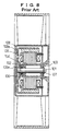
- the double row bearing device employed in the blower for cooling the office automation equipment includes a pair of ball bearings 102 and 103 fit on a shaft 101 of the motor as shown in Fig. 8.
- Inner rings 102a, 103a of each ball bearing 102, 103 are loose fit to the shaft 101, and outer rings 102b, 103b are also loose fit within the sleeve 104 being the bearing housing.
- a compressed coil spring 106 for applying pre-load to both ball bearings is interposed between the outer surface of the inner ring 102a of the left ball bearing 102 disposed adjacent the yoke 105 and the front face plate 105a of the yoke 105 integrally connected to the front face plate 108a of the impeller 108.
- a stop ring 107 for retaining the ball bearing 103 is provided around the right end of the shaft 101 and secured thereto.
- the clearance defined between the yoke 105 and the ball bearing 102 is very narrow, making it difficult to incorporate the compressed spring 106 into the clearance. Further, the necessity of incorporation of the spring into the clearance upon assembling the blower will make the assembling operation complicated.
- the level of the pre-loading force depends exclusively upon the distance between the yoke 105 and the bearing 102. Setting such distance is difficult and therefore, applying suitable amount of pre-loading force is difficult.
- the sleeve 104 has at both ends thereof larger inner diameter portions 104a, 104b for accommodating the outer rings of the ball bearings.
- Each of the larger inner diameter portions includes a shoulder respectively to which the outer ring of the ball bearing will be abutted.
- the blower employing the double row bearing device of the prior art requires a pair of ball bearings including an inner and an outer ring. A complicated operation for inserting the pre-loading spring is required. This involves a high cost for manufacturing the bearing device.
- the diameter of the shaft of the bearing device of the prior art is smaller than that of the sleeve by twice the sum of the thickness of the inner and outer rings of the ball bearings fit around the shaft. Therefore, it is difficult to provide durability, prevent rotational run out, and reduce generation of vibrations or noise.
- the object of the present invention is to provide a blower including a bearing structure wherein the number of components is reduced, assembly is easy, manufacturing cost is reduced, and the diameter of the shaft is increased being good at its durability, further eliminating rotational run out and providing superior quietness.
- blower in accordance with the first aspect of the present invention having an impeller adapted to be rotated upon energizing the blower comprising;
- blower in accordance with the second aspect of the present invention comprising;
- blower in accordance with the third aspect of the present invention comprising;
- the blower in accordance with the fourth aspect of the present invention comprising; a frame including a base connected through stays to the frame so as to be positioned at the central portion of the frame,
- blower in accordance with the fifth aspect of the present invention comprising;
- the balls for the first and second rows of any of the first to the fifth aspects of the present invention are made of ceramic material.
- the outer diameter of the inner ring of any of the first to the fifth aspects of the present invention are the same as that of the larger diameter portion of the shaft, and the diameter of the balls for the first row is the same as that of the balls for the second row.
- the blower in accordance with this embodiment is of a shaft rotating type.
- the frame of the body of the blower is designated by the reference numeral 1 in Figs. 1-3.
- the frame is preferably made of synthetic resin.
- a base 3 is supported through a few stays 2 by means of the frame formed integrally therewith.
- the outer periphery of the base 3 is formed with a flange 3a protruding frontward forming a relatively flat cylindrical configuration.
- the base 3 also has a cylindrical bearing holder 4 protruding frontward formed integrally therewith.
- a stator 5 including an iron core 5a and coils 5b is provided around the exterior surface of the bearing holder 4.
- a sleeve 6 served as an outer ring of the bearing is secured by adhesive within the interior of the bearing holder 4.
- a shaft 7 to be journalled through bearing means described hereinafter is disposed within the sleeve 6.
- a hub 8c for a central aperture provided through a front face plate 8a of a rotor or yoke 8 is fit and secured thereto.
- the yoke 8 has at its outer periphery a flange 8b extending rearward, on the inner surface of which is provided with a magnet 9 corresponding to the stator 5.
- the front face plate 8a of the yoke 8 is secured by any known means such as rivets 12 to a front face plate 10a of an impeller 10 having at its periphery a flange 10b extending rearward.
- the impeller 10 includes suitable number of blades 11 attached to the outer periphery of the flange.
- the reference numeral 13 is added to a printed circuit board connected at its terminals to the coil of the stator.
- the printed circuit board is secured to the iron core holder 14 of the stator by means of machine screws 15.
- the reference numeral 16 is added to leads to the printed circuit board, and the reference numeral 17 is added to a space in which electrical components are to be accommodated.
- the reference numeral 18 is added to a dust proof washer of resinous material fit around the outer periphery of the shaft 7.
- the washer serves to prevent the dusts from immigrating through the clearance defined between the sleeve 6 and the shaft 7 into the bearing device.
- the present invention relates especially to the structure of the bearing apparatus for journaling the shaft.
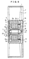
- the structure of the bearing device will now be described in detail with reference to Fig. 4.
- the shaft 7 is a stepped shaft including a larger diameter portion 7a and a reduced diameter portion 7b provided at one end of the shaft.
- the first inner raceway groove 19a is formed around the outer periphery of the larger diameter portion at a suitable position.
- the first outer raceway groove 19b is formed on the inner peripheral surface of said sleeve 6 so as to be positioned opposite to the first inner raceway groove 19a.
- a plurality of balls 20a of metallic or ceramic material for the first row are interposed between both grooves 19a, 19b.
- An inner ring 21 of the same outer diameter as that of the larger diameter portion of the shaft is fit slidably over the reduced diameter portion 7b of the shaft.
- the second inner raceway groove 22a is formed around the outer peripheral surface of the inner ring.
- the second outer raceway groove 22b is formed on the inner peripheral surface of said sleeve so as to be positioned opposite to the second inner raceway groove 22a.
- a plurality of balls 20b of steel or ceramic material for the second row are interposed between both grooves 22a, 22b.
- a stop ring 23 is provided around the outer periphery of the distal end of the reduced diameter portion.
- a pre-loading spring 24 is interposed between the stop ring 23 and the end surface of the inner ring 21.
- the spring 24 may be a helical spring as shown in Figs. 3 and 4, or any other spring such as a disc spring or a leaf spring.
- the balls 20a, 20b are equal in their diameter.
- the balls of ceramic material are higher in their hardness, and good at their abrasive resistance and durability.
- the blower including a bearing of which the balls are of ceramic material can be used in high rotational speed, assuring the quietness thereof.
- the assembling operation of the bearing device will be effected through the following steps; a plurality of balls 20a are disposed between the first inner raceway groove 19a formed around the shaft and the first outer raceway groove 19b formed within the sleeve, a plurality of balls 20b are disposed between the second inner raceway groove 22a formed around the inner ring and the second outer raceway groove 22b formed within the sleeve, then the pre-loading spring 24 is urged against the end face of the inner ring 21, and the stop ring 23 is secured to the reduced diameter portion 7b of the shaft with applying the pre-loading force due to the elastic force of the spring to the end face of the inner ring 21 in parallel to the axis of the shaft.
- the blower in accordance with the first embodiment can be assembled easily in the following steps; attaching the stator 5 to the cylindrical bearing holder 4 of the base 3, fitting or securing the central hub 8c of the yoke 8 around which the impeller 10 is connected integrally therewith to the shaft 7 of the bearing device assembled as described above and applied thereto a suitable pre-load by the spring 24, and then fitting the sleeve 6 of the bearing apparatus into the cylindrical bearing holder 4 of the base 3 and bonded thereto.
- the shaft of higher rigidity good at durability, inhibited in its rotational run out, and superior quietness can be provided.
- the bearing device of the present invention is a double row bearing device, it is unnecessary to employ a pair of ball bearings. This is because the single sleeve having the first and the second raceway grooves formed on the inner peripheral surface thereof will serve as outer rings of the ball bearings.
- the pre-loading spring has been incorporated preliminary into the bearing so that the delicate and complicated operation required in the blower of the prior art for incorporating the pre-loading spring into the small space can be precluded.
- the blower in accordance with this embodiment is a blower of a sleeve rotating type in which the shaft is stationary.
- the blower of this embodiment will now be described in detail with reference to Fig. 5.
- the frame 1 is of substantially the same structure as that of the first embodiment and includes a base 3 positioned at the central portion of the frame.
- the base 3 has a cylindrical bearing holder 4 formed integrally therewith and extending frontward (i.e. leftward in Fig. 5) therefrom.
- a stator 5 including an iron core 5a and coils 5b is attached to the outer surface of the cylindrical bearing holder 4.
- the bearing device including a sleeve 6, a shaft 7 and balls 20a, 20b interposed as double row therebetween is adapted to be inserted into the cylindrical bearing holder 4 in the reverse direction to that shown in Fig. 4.
- the larger diameter portion 7a is inserted into a boss 26 of the base 3, and secured thereto by means of a machine screw 25.
- the outer diameter of the sleeve 6 is smaller than the inner diameter of the holder 4 so as to rotate within the holder 4.
- the front end portion of the sleeve 6 is adapted to be inserted into a hub 8c for a central aperture provided through a front face plate 8a of a yoke 8, and secured thereto.
- the yoke 8 has at its periphery a rearward (i.e. rightward in Fig. 5) extending flange 8b, on the inner surface of which is provided with a magnet 9 corresponding to the stator 5.
- the front face plate 8a of the yoke 8 is secured by any known means such as rivets 12 to a front face plate 10a of an impeller 10 having at its periphery a rearward extending flange 10b.
- the impeller 10 includes suitable numbers of blades 11 attached to the outer periphery of the flange.
- the blower of this embodiment can be assembled easily in the following steps; attaching the stator 5 to the cylindrical bearing holder 4 of the base 3, fitting the sleeve 6 of the bearing device into the hub 8c of the yoke and secured thereto to connect the impeller to the bearing, inserting the sleeve 6 of the bearing device into the cylindrical bearing holder 4 of the base 3 so as to be concentric therewith, and securing the rear end of the shaft to the boss 26 of the base by means of the machine screw 25.
- blower in accordance with this embodiment is also of the sleeve rotating type in which the shaft is stationary.
- the blower of this embodiment will now be described in detail with reference to Fig. 6.
- the blower of this embodiment can be distinguished from those of the above mentioned embodiments in that the base 3 does not have the cylindrical bearing holder, the yoke is a cylindrical member, and the stator 5 is secured to the base.
- the blower includes the stator attached to the inner peripheral surface of the flange 3a extending frontward from the base 3, and a magnet 9 connected to the annular yoke 8 fit around the exterior of the sleeve 6 of the bearing device of Fig. 4 and secured thereto.
- the outer periphery of the magnet 9 are spaced a distance from the inner peripheral surface of the stator 5.
- the front end portion of the sleeve 6 is adapted to be inserted into the hub 27a for a central aperture provided through a supporting plate 27 and secured thereto.
- the supporting plate 27 is secured by any known means such as rivets 12 to a front plate portion 10a of an impeller 10.
- the blower of this embodiment can be assembled easily in the following steps; attaching the stator 5 to the flange 3a of the base, fitting the sleeve 6 into the hub 27a of the supporting plate 27 connected integrally to the impeller 10 and secured thereto, mounting the yoke 8 and the magnet 9 on the sleeve 6 to form a bearing apparatus, inserting thus obtained bearing device into the stator 5, and securing the rear end of the shaft to a boss 26 of the base 3 by means of a machine screw 25.
- the blower in accordance with this embodiment includes the base 3 having a flange 3b extending backward from the outer periphery thereof to form a cylindrical body with a bottom having an opening at the rear end thereof.
- the cylindrical body is occluded by a cover 28 to define a sealed chamber 29 for accommodating electric equipment.
- the accommodating chamber 29 is adapted to accommodate the electrical equipment such as a printed circuit board 13 or other electronic parts 30.
- a plurality of internally threaded bosses 3c are extending backward (rightwards in the drawings) from the bottom of the base 3 to detachably mount the cover to the base 3 by engaging screws 31 extending through the cover 28 with the internal threads of the bosses.
- the reference numeral 32 is added to leads for delivering electricity to the coil 5b of the stator 5 extend through legs 14a of the iron core holder 14 of the stator and connected to the printed circuit board 13.
- the structure of the blower of this fourth embodiment is substantially the same as that of the first embodiment but for the fact that the chamber 29 is a sealed one.
- the blower in accordance with the fourth embodiment is provided at the rear side of the base with a chamber for accommodating electrical equipment so that the printed circuit board or electronic parts can be protected from moisture, dirt, dusts, or other harmful gas or substance contained in a wind generated through the wind tunnel portion, and the degradation of the insulating property such as the electric insulation or dielectric strength can be avoided.
- the reliability of the blower or the equipment incorporated within the blower can be enhanced.
- the bearing apparatus of the blower in accordance with the present invention does not require a conventional ball bearing including both inner and outer rings, so that the diameter of the larger diameter portion of the shaft can be enlarged by the sum of the thickness of the inner and outer rings of the ball bearing, and the diameter of the reduced diameter portion of the shaft can also be enlarged by the thickness of the outer ring of the ball bearing, i.e. generally thick shaft can be obtained.
- the bearing device of the present invention is a double row bearing device, it is unnecessary to employ a pair of ball bearings. This is because the single sleeve having the first and the second outer raceway grooves formed on the inner peripheral surface thereof will serve as outer ring of the ball bearings.
- the preliminary completed bearing apparatus in which a suitable amount of pre-loading force is applied by means of the pre-loading spring may be incorporated into the base or the rotor hub of the blower, since the pre-loading spring had been incorporated preliminary into the bearing device itself.
Landscapes
- Engineering & Computer Science (AREA)
- Mechanical Engineering (AREA)
- General Engineering & Computer Science (AREA)
- Structures Of Non-Positive Displacement Pumps (AREA)
- Support Of The Bearing (AREA)
Abstract
Description
- The present invention relates especially to a blower suitable in the application for cooling office automation equipment.
- Conventionally, the double row bearing device employed in the blower for cooling the office automation equipment includes a pair of
ball bearings shaft 101 of the motor as shown in Fig. 8. -
Inner rings shaft 101, andouter rings sleeve 104 being the bearing housing. - A
compressed coil spring 106 for applying pre-load to both ball bearings is interposed between the outer surface of theinner ring 102a of theleft ball bearing 102 disposed adjacent theyoke 105 and thefront face plate 105a of theyoke 105 integrally connected to thefront face plate 108a of theimpeller 108. Astop ring 107 for retaining the ball bearing 103 is provided around the right end of theshaft 101 and secured thereto. - However, in the case of the pre-loading means as shown in Fig. 9, the clearance defined between the
yoke 105 and the ball bearing 102 is very narrow, making it difficult to incorporate thecompressed spring 106 into the clearance. Further, the necessity of incorporation of the spring into the clearance upon assembling the blower will make the assembling operation complicated. The level of the pre-loading force depends exclusively upon the distance between theyoke 105 and thebearing 102. Setting such distance is difficult and therefore, applying suitable amount of pre-loading force is difficult. - The
sleeve 104 has at both ends thereof largerinner diameter portions inner diameter portions - As it can be seen from the above, the blower employing the double row bearing device of the prior art requires a pair of ball bearings including an inner and an outer ring. A complicated operation for inserting the pre-loading spring is required. This involves a high cost for manufacturing the bearing device.
- The bigger the diameter of the motor shaft is, the higher is the rigidity of the shaft, and thus the rotational run out is reduced and a quiet motor with high durability can be obtained. However, the diameter of the shaft of the bearing device of the prior art is smaller than that of the sleeve by twice the sum of the thickness of the inner and outer rings of the ball bearings fit around the shaft. Therefore, it is difficult to provide durability, prevent rotational run out, and reduce generation of vibrations or noise.
- Accordingly, the object of the present invention is to provide a blower including a bearing structure wherein the number of components is reduced, assembly is easy, manufacturing cost is reduced, and the diameter of the shaft is increased being good at its durability, further eliminating rotational run out and providing superior quietness.
- These and other objects are achieved by a blower in accordance with the first aspect of the present invention having an impeller adapted to be rotated upon energizing the blower comprising;
- a bearing device for supporting a rotational center portion of the impeller, the bearing device including;
- a sleeve,
- a stepped shaft including a larger diameter portion and a reduced diameter portion provided at one end thereof,
- the first inner raceway groove formed at an appropriate position around the outer peripheral surface of the larger diameter portion,
- the first outer raceway groove formed on an inner peripheral surface of the sleeve so as to correspond with the first inner raceway groove,
- balls of the first row interposed between the first and second grooves,
- an inner ring slidably fit over the reduced diameter portion,
- the second inner raceway groove formed around an outer peripheral surface of the inner ring,
- the second outer raceway groove formed on the inner peripheral surface of the sleeve so as to correspond with the second inner raceway groove,
- balls of the second row interposed between the second inner and outer grooves,
- a stop ring provided around the inner periphery of the distal end of the reduced diameter portion, and
- a pre-loading spring interposed between the stop ring and an end surface of the inner ring to provide a suitable amount of pre-loading force to the inner ring.
-
- The blower in accordance with the second aspect of the present invention comprising;
- a frame including a base connected through stays to the frame so as to be positioned at the central portion of the frame,
- a cylindrical bearing holder formed integrally with the base to extend therefrom forwardly,
- a stator including an iron core and a coil and mounted on the exterior of the cylindrical bearing holder,
- an impeller including a front face plate, a flange formed over the outer periphery of the front face plate, and suitable numbers of blades provided on the outer periphery of the flange,
- a yoke including a front face plate to which the front face plate of the impeller is secured, a flange formed over the outer periphery of the front face plate, a magnet mounted on the flange, and
- a bearing device for supporting the central portion of the yoke through a shaft of the bearing device to which the central portion of the yoke is fit and secured thereto, the bearing device including;
- a sleeve,
- a stepped shaft including a larger diameter portion and a reduced diameter portion provided at one end thereof,
- the first inner raceway groove formed at an appropriate position around the outer peripheral surface of the larger diameter portion,
- the first outer raceway groove formed on an inner peripheral surface of the sleeve so as to correspond with the first inner raceway groove,
- balls of the first row interposed between the first and second grooves,
- an inner ring slidably fit over the reduced diameter portion,
- the second inner raceway groove formed around an outer peripheral surface of the inner ring,
- the second outer raceway groove formed on the inner peripheral surface of the sleeve so as to correspond with the second inner raceway groove,
- balls of the second row interposed between the third and fourth grooves,
- a stop ring provided around the inner periphery of the distal end of the reduced diameter portion, and
- a pre-loading spring interposed between the stop ring and an end surface of the inner ring to provide a suitable amount of pre-loading force to the inner ring.
-
- The blower in accordance with the third aspect of the present invention comprising;
- a frame including a base connected through stays to the frame so as to be positioned at the central portion of the frame,
- a cylindrical bearing holder formed integrally with the base to extend therefrom forwardly,
- a stator including an iron core and a coil and mounted on the exterior of the cylindrical bearing holder,
- an impeller including a front face plate, a flange formed over the outer periphery of the front face plate, and suitable numbers of blades provided on the outer periphery of the flange,
- a yoke including a front face plate to which the front face plate of the impeller is secured, a flange formed over the outer periphery of the front face plate, a magnet mounted on the flange, and
- a bearing device for supporting the central portion of the yoke through a sleeve of the bearing apparatus to which the central portion of the yoke is fit and secured thereto, the bearing device including;
- a sleeve,
- a stepped shaft including a larger diameter portion and a reduced diameter portion provided at one end thereof,
- the first inner raceway groove formed at an appropriate position around the outer peripheral surface of the larger diameter portion,
- the first outer raceway groove formed on an inner peripheral surface of the sleeve so as to correspond with the first inner raceway groove,
- balls of the first row interposed between the first and second grooves,
- an inner ring slidably fit over the reduced diameter portion,
- the second inner raceway groove formed around an outer peripheral surface of the inner ring,
- the second outer raceway groove formed on the inner peripheral surface of the sleeve so as to correspond with the second inner raceway groove,
- balls of the second row interposed between the third and fourth grooves,
- a stop ring provided around the inner periphery of the distal end of the reduced diameter portion, and
- a pre-loading spring interposed between the stop ring and an end surface of the inner ring to provide a suitable amount of pre-loading force to the inner ring.
-
- The blower in accordance with the fourth aspect of the present invention comprising; a frame including a base connected through stays to the frame so as to be positioned at the central portion of the frame,
- a cylindrical bearing holder formed integrally with the base to extend therefrom forwardly,
- a stator including an iron core and a coil and mounted on the exterior of the cylindrical bearing holder,
- an impeller including a front face plate, a flange formed over the outer periphery of the front face plate, and suitable number of blades provided on the outer periphery of the flange,
- a yoke including a front face plate to which the front face plate of the impeller is secured, a flange formed over the outer periphery of the front face plate, a magnet mounted on the flange, and
- a bearing device for supporting the central portion of the yoke through a sleeve thereof to which the central portion of the yoke is fit and secured thereto, the bearing device including;
- a sleeve,
- a stepped shaft including a larger diameter portion and a reduced diameter portion provided at one end thereof,
- the first inner raceway groove formed at an appropriate position around the outer peripheral surface of the larger diameter portion,
- the first outer raceway groove formed on an inner peripheral surface of the sleeve so as to correspond with the first inner raceway groove,
- balls of the first row interposed between the first and second grooves,
- an inner ring slidably fit over the reduced diameter portion,
- the second inner raceway groove formed around an outer peripheral surface of the inner ring,
- the second outer raceway groove formed on the inner peripheral surface of the sleeve so as to correspond with the second inner raceway groove,
- balls of the second row interposed between the third and fourth grooves,
- a stop ring provided around the inner periphery of the distal end of the reduced diameter portion, and
- a pre-loading spring interposed between the stop ring and an end surface of the inner ring to provide a suitable amount of pre-loading force to the inner ring, wherein
- the bearing device is provided within the cylindrical bearing holder so that the sleeve can be rotated around the axis of the bearing device, and the end of the shaft is secured to the base.
-
- The blower in accordance with the fifth aspect of the present invention comprising;
- a frame including a base connected through stays to the frame so as to be positioned at the central portion of the frame,
- a stator including an iron core and a coil and mounted on the inner peripheral surface of a flange extending forwardly from an outer periphery of the base,
- an impeller including a front face plate, a flange formed over the outer periphery of the front face plate, and suitable numbers of blades provided on the outer periphery of the flange,
- a bearing device for supporting the central portion of a supporting plate mounted on the rear surface of the front face plate, the bearing device including;
- a sleeve to which the central portion of the supporting plate is fit and secured,
- a stepped shaft including a larger diameter portion and a reduced diameter portion provided at one end thereof,
- the first inner raceway groove formed at an appropriate position around the outer peripheral surface of the larger diameter portion,
- the first outer raceway groove formed on an inner peripheral surface of the sleeve so as to correspond with the first inner raceway groove,
- balls of the first row interposed between the first and second grooves,
- an inner ring slidably fit over the reduced diameter portion,
- the second inner raceway groove formed around an outer peripheral surface of the inner ring,
- the second outer raceway groove formed on the inner peripheral surface of the sleeve so as to correspond with the second inner raceway groove,
- balls of the second row interposed between the second inner and outer grooves,
- a stop ring provided around the inner periphery of the distal end of the reduced diameter portion, and
- a pre-loading spring interposed between the stop ring and an end surface of the inner ring to provide a suitable amount of pre-loading force to the inner ring, wherein
- the exterior of the sleeve of the bearing apparatus is provided with a cylindrical yoke on which a magnet corresponding to the coil of the stator is provided, and the end of the shaft is secured to the base.
-
- In the blower in accordance with the sixth to the tenth aspect of the present invention, the balls for the first and second rows of any of the first to the fifth aspects of the present invention, are made of ceramic material.
- In the blower in accordance with the eleventh to the fifteenth aspect of the present invention, the outer diameter of the inner ring of any of the first to the fifth aspects of the present invention are the same as that of the larger diameter portion of the shaft, and the diameter of the balls for the first row is the same as that of the balls for the second row.
- Further feature of the present invention will become apparent to those skilled in the art to which the present invention relates from reading the following specification with reference to the accompanying drawings, in which:
- Fig. 1 is an elevational view showing the first embodiment of the blower in accordance with the present invention;
- Fig. 2 is a rear elevational view showing the first embodiment of the blower in accordance with the present invention;
- Fig. 3 is a longitudinal sectional view showing the first embodiment of the blower in accordance with the present invention;
- Fig. 4 is an enlarged cross-sectional view showing the bearing device of the blower in accordance with the present invention;
- Fig. 5 is a longitudinal sectional view showing the second embodiment of the blower in accordance with the present invention;
- Fig. 6 is a longitudinal sectional view showing the third embodiment of the blower in accordance with the present invention;
- Fig. 7 is a longitudinal sectional view showing the third embodiment of the blower in accordance with the present invention;
- Fig. 8 is a longitudinal sectional view showing an example of the blower of the prior art; and
- Fig. 9 is an enlarged cross-sectional view showing the bearing device of the blower of the prior art.
-
- Preferred embodiments in accordance with the present invention will now be described with reference to the attached drawings.
- The blower in accordance with this embodiment is of a shaft rotating type. The frame of the body of the blower is designated by the
reference numeral 1 in Figs. 1-3. The frame is preferably made of synthetic resin. - A
base 3 is supported through afew stays 2 by means of the frame formed integrally therewith. The outer periphery of thebase 3 is formed with aflange 3a protruding frontward forming a relatively flat cylindrical configuration. - The
base 3 also has acylindrical bearing holder 4 protruding frontward formed integrally therewith. Astator 5 including aniron core 5a andcoils 5b is provided around the exterior surface of thebearing holder 4. Asleeve 6 served as an outer ring of the bearing is secured by adhesive within the interior of thebearing holder 4. - A
shaft 7 to be journalled through bearing means described hereinafter is disposed within thesleeve 6. At the distal end of the shaft protruding through thesleeve 6, ahub 8c for a central aperture provided through afront face plate 8a of a rotor oryoke 8 is fit and secured thereto. - The
yoke 8 has at its outer periphery aflange 8b extending rearward, on the inner surface of which is provided with amagnet 9 corresponding to thestator 5. - The
front face plate 8a of theyoke 8 is secured by any known means such asrivets 12 to afront face plate 10a of animpeller 10 having at its periphery aflange 10b extending rearward. Theimpeller 10 includes suitable number ofblades 11 attached to the outer periphery of the flange. - The
reference numeral 13 is added to a printed circuit board connected at its terminals to the coil of the stator. The printed circuit board is secured to theiron core holder 14 of the stator by means ofmachine screws 15. Thereference numeral 16 is added to leads to the printed circuit board, and thereference numeral 17 is added to a space in which electrical components are to be accommodated. - The
reference numeral 18 is added to a dust proof washer of resinous material fit around the outer periphery of theshaft 7. The washer serves to prevent the dusts from immigrating through the clearance defined between thesleeve 6 and theshaft 7 into the bearing device. - In the blower of the above mentioned arrangement, energizing the coil of the stator rotates the
yoke 8, and thus theimpeller 10 connected to the yoke to provide a blow of wind by theblades 11. - Hence, the present invention relates especially to the structure of the bearing apparatus for journaling the shaft. The structure of the bearing device will now be described in detail with reference to Fig. 4.
- The
shaft 7 is a stepped shaft including alarger diameter portion 7a and a reduceddiameter portion 7b provided at one end of the shaft. The firstinner raceway groove 19a is formed around the outer periphery of the larger diameter portion at a suitable position. The firstouter raceway groove 19b is formed on the inner peripheral surface of saidsleeve 6 so as to be positioned opposite to the firstinner raceway groove 19a. A plurality ofballs 20a of metallic or ceramic material for the first row are interposed between bothgrooves - An
inner ring 21 of the same outer diameter as that of the larger diameter portion of the shaft is fit slidably over the reduceddiameter portion 7b of the shaft. The secondinner raceway groove 22a is formed around the outer peripheral surface of the inner ring. The secondouter raceway groove 22b is formed on the inner peripheral surface of said sleeve so as to be positioned opposite to the secondinner raceway groove 22a. A plurality ofballs 20b of steel or ceramic material for the second row are interposed between bothgrooves - A
stop ring 23 is provided around the outer periphery of the distal end of the reduced diameter portion. A pre-loadingspring 24 is interposed between thestop ring 23 and the end surface of theinner ring 21. Thespring 24 may be a helical spring as shown in Figs. 3 and 4, or any other spring such as a disc spring or a leaf spring. - The
balls - The blower including a bearing of which the balls are of ceramic material can be used in high rotational speed, assuring the quietness thereof.
- The assembling operation of the bearing device will be effected through the following steps; a plurality of
balls 20a are disposed between the firstinner raceway groove 19a formed around the shaft and the firstouter raceway groove 19b formed within the sleeve, a plurality ofballs 20b are disposed between the secondinner raceway groove 22a formed around the inner ring and the secondouter raceway groove 22b formed within the sleeve, then thepre-loading spring 24 is urged against the end face of theinner ring 21, and thestop ring 23 is secured to the reduceddiameter portion 7b of the shaft with applying the pre-loading force due to the elastic force of the spring to the end face of theinner ring 21 in parallel to the axis of the shaft. - The blower in accordance with the first embodiment can be assembled easily in the following steps; attaching the
stator 5 to thecylindrical bearing holder 4 of thebase 3, fitting or securing thecentral hub 8c of theyoke 8 around which theimpeller 10 is connected integrally therewith to theshaft 7 of the bearing device assembled as described above and applied thereto a suitable pre-load by thespring 24, and then fitting thesleeve 6 of the bearing apparatus into thecylindrical bearing holder 4 of thebase 3 and bonded thereto. - As seen from the above, thus assembled blower does not require a conventional ball bearing including both inner and outer ring, so that the diameter of the
larger diameter portion 7a of the shaft can be enlarged by the sum of the thickness of the inner and outer rings of the ball bearing, and the diameter of the reduceddiameter portion 7b of the shaft can also be enlarged by the thickness of the outer ring of the ball bearing, i.e. generally thick shaft can be obtained. - Accordingly, the shaft of higher rigidity, good at durability, inhibited in its rotational run out, and superior quietness can be provided.
- Although the bearing device of the present invention is a double row bearing device, it is unnecessary to employ a pair of ball bearings. This is because the single sleeve having the first and the second raceway grooves formed on the inner peripheral surface thereof will serve as outer rings of the ball bearings.
- In other words, it is unnecessary to use two outer rings of the bearings other than the sleeve, and only one inner ring is required on the reduced diameter portion of the shaft.
- Further, the pre-loading spring has been incorporated preliminary into the bearing so that the delicate and complicated operation required in the blower of the prior art for incorporating the pre-loading spring into the small space can be precluded.
- The blower in accordance with this embodiment is a blower of a sleeve rotating type in which the shaft is stationary. The blower of this embodiment will now be described in detail with reference to Fig. 5.
- The
frame 1 is of substantially the same structure as that of the first embodiment and includes abase 3 positioned at the central portion of the frame. Thebase 3 has acylindrical bearing holder 4 formed integrally therewith and extending frontward (i.e. leftward in Fig. 5) therefrom. Astator 5 including aniron core 5a andcoils 5b is attached to the outer surface of thecylindrical bearing holder 4. - The bearing device including a
sleeve 6, ashaft 7 andballs cylindrical bearing holder 4 in the reverse direction to that shown in Fig. 4. In this arrangement, thelarger diameter portion 7a is inserted into aboss 26 of thebase 3, and secured thereto by means of amachine screw 25. The outer diameter of thesleeve 6 is smaller than the inner diameter of theholder 4 so as to rotate within theholder 4. - The front end portion of the
sleeve 6 is adapted to be inserted into ahub 8c for a central aperture provided through afront face plate 8a of ayoke 8, and secured thereto. Theyoke 8 has at its periphery a rearward (i.e. rightward in Fig. 5) extendingflange 8b, on the inner surface of which is provided with amagnet 9 corresponding to thestator 5. - The
front face plate 8a of theyoke 8 is secured by any known means such asrivets 12 to afront face plate 10a of animpeller 10 having at its periphery a rearward extendingflange 10b. Theimpeller 10 includes suitable numbers ofblades 11 attached to the outer periphery of the flange. - In the blower of the above mentioned arrangement, energizing the coil of the stator rotates the
yoke 8 together with the sleeve, and thus theimpeller 10 connected to the yoke to provide a blow of wind by theblades 11. - The blower of this embodiment can be assembled easily in the following steps; attaching the
stator 5 to thecylindrical bearing holder 4 of thebase 3, fitting thesleeve 6 of the bearing device into thehub 8c of the yoke and secured thereto to connect the impeller to the bearing, inserting thesleeve 6 of the bearing device into thecylindrical bearing holder 4 of thebase 3 so as to be concentric therewith, and securing the rear end of the shaft to theboss 26 of the base by means of themachine screw 25. - The blower in accordance with this embodiment is also of the sleeve rotating type in which the shaft is stationary. The blower of this embodiment will now be described in detail with reference to Fig. 6.
- The blower of this embodiment can be distinguished from those of the above mentioned embodiments in that the
base 3 does not have the cylindrical bearing holder, the yoke is a cylindrical member, and thestator 5 is secured to the base. - The blower includes the stator attached to the inner peripheral surface of the
flange 3a extending frontward from thebase 3, and amagnet 9 connected to theannular yoke 8 fit around the exterior of thesleeve 6 of the bearing device of Fig. 4 and secured thereto. The outer periphery of themagnet 9 are spaced a distance from the inner peripheral surface of thestator 5. - The front end portion of the
sleeve 6 is adapted to be inserted into thehub 27a for a central aperture provided through a supportingplate 27 and secured thereto. The supportingplate 27 is secured by any known means such asrivets 12 to afront plate portion 10a of animpeller 10. - In the blower of the above mentioned arrangement, energizing the coil of the stator rotates the
yoke 8 together with thesleeve 6, and thus theimpeller 10 connected to the sleeve through the supportingplate 27 to provide a blow of wind by theblades 11. - The blower of this embodiment can be assembled easily in the following steps; attaching the
stator 5 to theflange 3a of the base, fitting thesleeve 6 into thehub 27a of the supportingplate 27 connected integrally to theimpeller 10 and secured thereto, mounting theyoke 8 and themagnet 9 on thesleeve 6 to form a bearing apparatus, inserting thus obtained bearing device into thestator 5, and securing the rear end of the shaft to aboss 26 of thebase 3 by means of amachine screw 25. - The blower in accordance with this embodiment includes the
base 3 having aflange 3b extending backward from the outer periphery thereof to form a cylindrical body with a bottom having an opening at the rear end thereof. The cylindrical body is occluded by acover 28 to define a sealedchamber 29 for accommodating electric equipment. Theaccommodating chamber 29 is adapted to accommodate the electrical equipment such as a printedcircuit board 13 or otherelectronic parts 30. - A plurality of internally threaded bosses 3c are extending backward (rightwards in the drawings) from the bottom of the
base 3 to detachably mount the cover to thebase 3 by engagingscrews 31 extending through thecover 28 with the internal threads of the bosses. - The
reference numeral 32 is added to leads for delivering electricity to thecoil 5b of thestator 5 extend throughlegs 14a of theiron core holder 14 of the stator and connected to the printedcircuit board 13. - The structure of the blower of this fourth embodiment is substantially the same as that of the first embodiment but for the fact that the
chamber 29 is a sealed one. - The blower in accordance with the fourth embodiment is provided at the rear side of the base with a chamber for accommodating electrical equipment so that the printed circuit board or electronic parts can be protected from moisture, dirt, dusts, or other harmful gas or substance contained in a wind generated through the wind tunnel portion, and the degradation of the insulating property such as the electric insulation or dielectric strength can be avoided. Thus, the reliability of the blower or the equipment incorporated within the blower can be enhanced.
- As seen from the above, the bearing apparatus of the blower in accordance with the present invention does not require a conventional ball bearing including both inner and outer rings, so that the diameter of the larger diameter portion of the shaft can be enlarged by the sum of the thickness of the inner and outer rings of the ball bearing, and the diameter of the reduced diameter portion of the shaft can also be enlarged by the thickness of the outer ring of the ball bearing, i.e. generally thick shaft can be obtained.
- Accordingly, a shaft of higher rigidity, good at durability, inhibited in its rotational run out, and superior quietness can be provided.
- Although the bearing device of the present invention is a double row bearing device, it is unnecessary to employ a pair of ball bearings. This is because the single sleeve having the first and the second outer raceway grooves formed on the inner peripheral surface thereof will serve as outer ring of the ball bearings.
- In other words, it is unnecessary to use two outer rings of the bearings other than the sleeve, and only one inner ring is required on the reduced diameter portion of the shaft.
- Further, the preliminary completed bearing apparatus in which a suitable amount of pre-loading force is applied by means of the pre-loading spring may be incorporated into the base or the rotor hub of the blower, since the pre-loading spring had been incorporated preliminary into the bearing device itself.
- The delicate and complicated operation required in the assembling operation of the blower of the prior art for incorporating the pre-loading spring into the small space can be precluded so that the assembling operation of the blower can be effected easily and quickly.
- Further, it is unnecessary to form lager inner diameter portions at the interior portions of both ends of the sleeve served also as the outer ring, so that the rotational run out caused by the eccentricity between the sleeve and the lager inner diameter portions and the generation of the noise accompanied therewith can be avoided.
- While particular embodiments of the present invention have been illustrated and described, it should be obvious to those skilled in the art that various changes and modifications can be made without departing from the spirit and scope of the invention.
Claims (7)
- A blower (1) having an impeller (10) rotated upon energising the blower comprising:a bearing device for supporting a rotational centre portion (10b) of the impeller (10), the bearing device including:a sleeve (6),a stepped shaft (7) including a larger diameter portion (7a) and a reduced diameter portion (7b) provided at one end thereof,a first inner raceway groove (19a) formed at an appropriate position around the outer peripheral surface of the larger diameter portion (7a),a first outer raceway groove (19b) formed on an inner peripheral surface of the sleeve (6) so as to correspond with said first inner raceway groove (19a),balls (20a) of a first row interposed between the first and second grooves (19a, 19b),an inner ring (21) slidably fitted over the reduced diameter portion (7b),a second inner raceway groove (22a) formed around an outer peripheral surface of the inner ring (21),a second outer raceway groove (22b) formed on the inner peripheral surface of said sleeve (6) so as to correspond with said second inner raceway groove (22a),balls (20) of a second row interposed between said second inner and outer raceway grooves (22a, 22b),a stop ring (23) provided around a distal end of the reduced diameter portion (7b), anda pre-loading spring (24) interposed between the stop ring (23) and an end surface of the inner ring (21) to provide a suitable amount of pre-loading force to the inner ring (21).
- A blower (1) comprising:a frame including a base (3) connected through stays (2) to the frame so as to be positioned at the central portion of said frame,a cylindrical bearing holder (4) formed integrally with said base (3) to extend forwardly therefrom,a stator (5) including an iron core (5a) and a coil (5b) and mounted on the exterior of the cylindrical bearing holder (4),an impeller (10) including a front face plate (10a), a flange (10b) formed over the outer periphery of the front face plate (10a), and a suitable number of blades (11) provided on the outer periphery of said flange (10b),a yoke (8) including a front face plate (8a) to which the front face plate (10a) of the impeller (10) is secured, a flange (8b) formed over the outer periphery of the front face plate (8a), a magnet (9) mounted on the flange (8b), anda bearing device for supporting the central portion of the yoke (8) through a shaft (7) of the bearing device to which the central portion of said yoke (8) is fitted and secured, the bearing device including:a sleeve (6),a stepped shaft (7) including a larger diameter portion (7a) and a reduced diameter portion (7b) provided at one end thereof,a first inner raceway groove (19a) formed at an appropriate position around the outer peripheral surface of the larger diameter portion (7a),a first outer raceway groove (19b) formed on an inner peripheral surface of the sleeve (6) so as to correspond with said first inner raceway groove (19a),balls (20a) of a first row interposed between said first and second grooves (19a, 19b),an inner ring (21) slidably fitted over the reduced diameter portion (7b),a second inner raceway groove (22a) constituting a third groove formed around an outer peripheral surface of the inner ring (21),a second outer raceway groove (22b) constituting a fourth groove formed on the inner peripheral surface of the sleeve (6) so as to correspond with said second inner raceway groove (22a),balls (20b) of a second row interposed between the third and fourth grooves (22a, 22b),a stop ring (23) provided around a distal end of the reduced diameter portion (7b), anda pre-loading spring (24) interposed between the stop ring (23) and an end surface of the inner ring (21) to provide a suitable amount of pre-loading force to the inner ring (21).
- A blower (1) comprising:a frame including a base (3) connected through stays (2) to the frame so as to be positioned at the central portion of said frame,a cylindrical bearing holder (4) formed integrally with said base (3) to extend forwardly therefrom,a stator (5) including an iron core (5a) and a coil (5b) and mounted on the exterior of the cylindrical bearing holder (4),an impeller (10) including a front face plate (10a), a flange (10b) formed over the outer periphery of the front face plate (10a), and a suitable number of blades (11) provided on the outer periphery of said flange (10b),a yoke (8) including a front face plate (8a) to which the front face plate (10a) of the impeller (10) is secured, a flange (8b) formed over the outer periphery of the front face plate (8a), a magnet (9) mounted on the flange (8b), anda bearing device for supporting the central portion of the yoke (8) through a sleeve (6) of said bearing device to which the central portion of said yoke (8) is fitted and secured, the bearing device including:a sleeve (6),a stepped shaft (7) including a larger diameter portion (7a) and a reduced diameter portion (7b) provided at one end thereof,a first inner raceway groove (19a) formed at an appropriate position around the outer peripheral surface of the larger diameter portion (7a),a first outer raceway groove (19b) formed on an inner peripheral surface of the sleeve (6) so as to correspond with said first inner raceway groove (19a),balls (20a) of a first row interposed between said first and second grooves (19a, 19b),an inner ring (21) slidably fitted over the reduced diameter portion (7b),a second inner raceway groove (22a) constituting a third groove formed around an outer peripheral surface of the inner ring (21),a second outer raceway groove (22b) constituting a fourth groove formed on the inner peripheral surface of the sleeve (6) so as to correspond with said second inner raceway groove (22a),balls (20b) of a second row interposed between the third and fourth grooves (22a, 22b),a stop ring (23) provided around a distal end of the reduced diameter portion (7b), anda pre-loading spring (24) interposed between the stop ring (23) and an end surface of the inner ring (21) to provide a suitable amount of pre-loading force to the inner ring (21).
- A blower (1) comprising:a frame including a base (3) connected through stays (2) to the frame so as to be positioned at the central portion of said frame,a cylindrical bearing holder (4) formed integrally with said base (3) to extend forwardly therefrom,a stator (5) including an iron core (5a) and a coil (5b) and mounted on the exterior of the cylindrical bearing holder (4),an impeller (10) including a front face plate (10a), a flange (10b) formed over the outer periphery of the front face plate (10a), and a suitable number of blades (11) provided on the outer periphery of said flange (10b),a yoke (8) including a front face plate (8a) to which the front face plate (10a) of the impeller (10) is secured, a flange (8b) formed over the outer periphery of the front face plate (8a), a magnet (9) mounted on the flange (8b), anda bearing device for supporting the central portion of the yoke (8) through a sleeve (8c) to which the central portion of said yoke (8) is fitted and secured, the bearing device including:a sleeve (6),a stepped shaft (7) including a larger diameter portion (7a) and a reduced diameter portion (7b) provided at one end thereof,a first inner raceway groove (19a) formed at an appropriate position around the outer peripheral surface of the larger diameter portion (7a),a first outer raceway groove (19b) formed on an inner peripheral surface of the sleeve (6) so as to correspond with said first inner raceway groove (19a),balls (20a) of a first row interposed between said first and second grooves (19a, 19b),an inner ring (21) slidably fitted over the reduced diameter portion (7b),a second inner raceway groove (22a) constituting a third groove formed around an outer peripheral surface of the inner ring (21),a second outer raceway groove (22b) constituting a fourth groove formed on the inner peripheral surface of the sleeve (6) so as to correspond with said second inner raceway groove (22a),balls (20b) of a second row interposed between the third and fourth grooves (22a, 22b),a stop ring (23) provided around a distal end of the reduced diameter portion (7b), anda pre-loading spring (24) interposed between the stop ring (23) and an end surface of the inner ring (21) to provide a suitable amount of pre-loading force to the inner ring (21), whereinthe bearing device is provided within the cylindrical bearing holder (4) so that the sleeve (6) can be rotated around the axis of the bearing device, and the end of the shaft is secured to the base.
- A blower (1) comprising:a frame including a base (3) connected through stays (2) to the frame so as to be positioned at the central portion of the frame,a stator (5) including an iron core (5a) and a coil (5b) and mounted on the inner peripheral surface of a flange (3a) extending forwardly from an outer periphery of the base (3),an impeller (10) including a front face plate (10a), a flange (10b) formed over the outer periphery of a front face plate (10a), and a suitable number of blades (11) provided on an outer periphery of the flange (10b),a bearing device for supporting the central portion of a supporting plate (27) mounted on the rear surface of said front face plate (10a), the bearing device including:a sleeve (6) to which a central portion (27a) of the supporting plate (27) is fitted and secured,a stepped shaft (7) including a larger diameter portion (7a) and a reduced diameter portion (7b) provided at one end thereof,a first inner raceway groove (19a) formed at an appropriate position around the outer peripheral surface of the larger diameter portion (7a),a first outer raceway groove (19b) formed on an inner peripheral surface of the sleeve (6) so as to correspond with said first inner raceway groove (19a),balls (20a) of a first row interposed between said first and second grooves (19a, 19b),an inner ring (21) slidably fitted over the reduced diameter portion (7b),a second inner raceway groove (22a) formed around an outer peripheral surface of the inner ring (21),a second outer raceway groove (22b) formed on the inner peripheral surface of said sleeve (6) so as to correspond with said second inner raceway groove (22a),balls (20b) of a second row interposed between said second inner and outer raceway grooves (22a, 22b),a stop ring (23) provided around a distal end of the reduced diameter portion (7b), anda pre-loading spring (24) interposed between said stop ring (23) and an end surface of said inner ring (21) to provide a suitable amount of pre-loading force to the inner ring (21), whereinthe exterior of the sleeve (6) of the bearing apparatus is provided with a cylindrical yoke (8) on which a magnet (9) corresponding to said coil (5b) of said stator (5) is provided, and the end of said shaft (7) is secured to the base (3).
- A blower according to any preceding claim wherein said balls (20a, 20b) of the first and second rows are made of ceramic material.
- A blower according to any preceding claim wherein the outer diameter of said inner ring (21) is the same as that of the larger diameter portion (7a) of said shaft (7), and diameter of said balls (20a) of the first row is the same as that of said balls (20b) of the second row.
Applications Claiming Priority (2)
| Application Number | Priority Date | Filing Date | Title |
|---|---|---|---|
| JP2000220900 | 2000-07-21 | ||
| JP2000220900A JP2002039091A (en) | 2000-07-21 | 2000-07-21 | Blower |
Publications (3)
| Publication Number | Publication Date |
|---|---|
| EP1174623A2 true EP1174623A2 (en) | 2002-01-23 |
| EP1174623A3 EP1174623A3 (en) | 2003-02-05 |
| EP1174623B1 EP1174623B1 (en) | 2008-01-02 |
Family
ID=18715420
Family Applications (1)
| Application Number | Title | Priority Date | Filing Date |
|---|---|---|---|
| EP01306058A Expired - Lifetime EP1174623B1 (en) | 2000-07-21 | 2001-07-13 | Blower |
Country Status (4)
| Country | Link |
|---|---|
| US (1) | US6511303B2 (en) |
| EP (1) | EP1174623B1 (en) |
| JP (1) | JP2002039091A (en) |
| DE (1) | DE60132138T2 (en) |
Cited By (2)
| Publication number | Priority date | Publication date | Assignee | Title |
|---|---|---|---|---|
| WO2013110473A3 (en) * | 2012-01-28 | 2014-01-03 | Brose Fahrzeugteile GmbH & Co. Kommanditgesellschaft, Würzburg | Radiator fan of a motor vehicle |
| WO2021178527A1 (en) * | 2020-03-03 | 2021-09-10 | Resmed Motor Technologies Inc. | Bearing sleeve for blower |
Families Citing this family (65)
| Publication number | Priority date | Publication date | Assignee | Title |
|---|---|---|---|---|
| US5345170A (en) * | 1992-06-11 | 1994-09-06 | Cascade Microtech, Inc. | Wafer probe station having integrated guarding, Kelvin connection and shielding systems |
| US6380751B2 (en) * | 1992-06-11 | 2002-04-30 | Cascade Microtech, Inc. | Wafer probe station having environment control enclosure |
| US6232789B1 (en) * | 1997-05-28 | 2001-05-15 | Cascade Microtech, Inc. | Probe holder for low current measurements |
| US5561377A (en) * | 1995-04-14 | 1996-10-01 | Cascade Microtech, Inc. | System for evaluating probing networks |
| US5914613A (en) * | 1996-08-08 | 1999-06-22 | Cascade Microtech, Inc. | Membrane probing system with local contact scrub |
| US6002263A (en) * | 1997-06-06 | 1999-12-14 | Cascade Microtech, Inc. | Probe station having inner and outer shielding |
| US6256882B1 (en) | 1998-07-14 | 2001-07-10 | Cascade Microtech, Inc. | Membrane probing system |
| JP2001309606A (en) * | 2000-04-19 | 2001-11-02 | Minebea Co Ltd | Compound-bearing motor for oa apparatus |
| JP2001304199A (en) * | 2000-04-19 | 2001-10-31 | Minebea Co Ltd | Blower |
| US6965226B2 (en) * | 2000-09-05 | 2005-11-15 | Cascade Microtech, Inc. | Chuck for holding a device under test |
| US6914423B2 (en) * | 2000-09-05 | 2005-07-05 | Cascade Microtech, Inc. | Probe station |
| DE20114544U1 (en) * | 2000-12-04 | 2002-02-21 | Cascade Microtech, Inc., Beaverton, Oreg. | wafer probe |
| US6970634B2 (en) * | 2001-05-04 | 2005-11-29 | Cascade Microtech, Inc. | Fiber optic wafer probe |
| AU2002327490A1 (en) | 2001-08-21 | 2003-06-30 | Cascade Microtech, Inc. | Membrane probing system |
| US6777964B2 (en) * | 2002-01-25 | 2004-08-17 | Cascade Microtech, Inc. | Probe station |
| US7352258B2 (en) * | 2002-03-28 | 2008-04-01 | Cascade Microtech, Inc. | Waveguide adapter for probe assembly having a detachable bias tee |
| WO2003100445A2 (en) * | 2002-05-23 | 2003-12-04 | Cascade Microtech, Inc. | Probe for testing a device under test |
| US6847219B1 (en) * | 2002-11-08 | 2005-01-25 | Cascade Microtech, Inc. | Probe station with low noise characteristics |
| US6724205B1 (en) * | 2002-11-13 | 2004-04-20 | Cascade Microtech, Inc. | Probe for combined signals |
| US6861856B2 (en) * | 2002-12-13 | 2005-03-01 | Cascade Microtech, Inc. | Guarded tub enclosure |
| TW568192U (en) * | 2003-01-27 | 2003-12-21 | Datech Technology Co Ltd | Metal bushing motor to fix in a fan |
| US7070336B2 (en) * | 2003-05-13 | 2006-07-04 | Sunonwealth Electric Machine Industry Co., Ltd. | Bearing positioning member for a spindle motor |
| US7492172B2 (en) * | 2003-05-23 | 2009-02-17 | Cascade Microtech, Inc. | Chuck for holding a device under test |
| US7057404B2 (en) * | 2003-05-23 | 2006-06-06 | Sharp Laboratories Of America, Inc. | Shielded probe for testing a device under test |
| US7086843B2 (en) * | 2003-06-13 | 2006-08-08 | Asia Vital Components Co., Ltd. | Cooling fan hub assembly |
| JP2005127319A (en) * | 2003-10-02 | 2005-05-19 | Nippon Densan Corp | Fan device |
| US7211915B2 (en) * | 2003-10-15 | 2007-05-01 | Hewlett-Packard Development Company, L.P. | Motor assembly using redundant bearings and support elements |
| US7250626B2 (en) * | 2003-10-22 | 2007-07-31 | Cascade Microtech, Inc. | Probe testing structure |
| US7187188B2 (en) * | 2003-12-24 | 2007-03-06 | Cascade Microtech, Inc. | Chuck with integrated wafer support |
| JP2007517231A (en) * | 2003-12-24 | 2007-06-28 | カスケード マイクロテック インコーポレイテッド | Active wafer probe |
| JP2005256749A (en) * | 2004-03-12 | 2005-09-22 | Nippon Densan Corp | Fan |
| JP3970260B2 (en) | 2004-04-23 | 2007-09-05 | 三菱重工業株式会社 | pump |
| DE202005021434U1 (en) * | 2004-06-07 | 2008-03-20 | Cascade Microtech, Inc., Beaverton | Thermo-optical clamping device |
| EP1766426B1 (en) * | 2004-07-07 | 2013-09-11 | Cascade Microtech, Inc. | Probe head having a membrane suspended probe |
| KR20070058522A (en) * | 2004-09-13 | 2007-06-08 | 캐스케이드 마이크로테크 인코포레이티드 | Double sided probing structures |
| US20060092505A1 (en) * | 2004-11-02 | 2006-05-04 | Umech Technologies, Co. | Optically enhanced digital imaging system |
| US20060169897A1 (en) * | 2005-01-31 | 2006-08-03 | Cascade Microtech, Inc. | Microscope system for testing semiconductors |
| US7535247B2 (en) * | 2005-01-31 | 2009-05-19 | Cascade Microtech, Inc. | Interface for testing semiconductors |
| US7656172B2 (en) * | 2005-01-31 | 2010-02-02 | Cascade Microtech, Inc. | System for testing semiconductors |
| US7449899B2 (en) * | 2005-06-08 | 2008-11-11 | Cascade Microtech, Inc. | Probe for high frequency signals |
| JP5080459B2 (en) * | 2005-06-13 | 2012-11-21 | カスケード マイクロテック インコーポレイテッド | Wideband active / passive differential signal probe |
| US7723999B2 (en) * | 2006-06-12 | 2010-05-25 | Cascade Microtech, Inc. | Calibration structures for differential signal probing |
| US7403028B2 (en) | 2006-06-12 | 2008-07-22 | Cascade Microtech, Inc. | Test structure and probe for differential signals |
| US7764072B2 (en) * | 2006-06-12 | 2010-07-27 | Cascade Microtech, Inc. | Differential signal probing system |
| US7443186B2 (en) * | 2006-06-12 | 2008-10-28 | Cascade Microtech, Inc. | On-wafer test structures for differential signals |
| US7766627B2 (en) * | 2006-12-12 | 2010-08-03 | Asia Vital Components Co., Ltd. | Motor device for a fan |
| JP2008196480A (en) * | 2007-01-16 | 2008-08-28 | Sanyo Denki Co Ltd | Axial-flow fan |
| US20080170935A1 (en) * | 2007-01-16 | 2008-07-17 | Sanyo Denki Co., Ltd. | Axial-flow fan |
| CN101285476A (en) * | 2007-04-13 | 2008-10-15 | 富准精密工业(深圳)有限公司 | Cooling fan |
| JP5169033B2 (en) * | 2007-06-12 | 2013-03-27 | 日本電産株式会社 | Axial fan |
| CN201090471Y (en) * | 2007-07-04 | 2008-07-23 | 鑫贺精密电子(东莞)有限公司 | Energy saving heat radiating fun of integrated shaping injection magnet ring |
| US7876114B2 (en) * | 2007-08-08 | 2011-01-25 | Cascade Microtech, Inc. | Differential waveguide probe |
| TWI349071B (en) * | 2008-02-01 | 2011-09-21 | Delta Electronics Inc | Fan |
| TWI370609B (en) * | 2008-02-05 | 2012-08-11 | Delta Electronics Inc | Foreign bodies-or water-proof fan and motor |
| JP5129667B2 (en) * | 2008-06-26 | 2013-01-30 | 山洋電気株式会社 | Axial blower |
| US7888957B2 (en) * | 2008-10-06 | 2011-02-15 | Cascade Microtech, Inc. | Probing apparatus with impedance optimized interface |
| US8410806B2 (en) | 2008-11-21 | 2013-04-02 | Cascade Microtech, Inc. | Replaceable coupon for a probing apparatus |
| US8319503B2 (en) | 2008-11-24 | 2012-11-27 | Cascade Microtech, Inc. | Test apparatus for measuring a characteristic of a device under test |
| TWI384127B (en) * | 2009-05-11 | 2013-02-01 | Sunonwealth Electr Mach Ind Co | Fan |
| CN102128173A (en) * | 2010-01-20 | 2011-07-20 | 鸿富锦精密工业(深圳)有限公司 | Fan |
| CN102192163A (en) * | 2010-03-08 | 2011-09-21 | 鸿富锦精密工业(深圳)有限公司 | Fan |
| EP2547910B1 (en) * | 2010-03-15 | 2018-05-16 | Ebm-Papst St. Georgen GmbH & CO. KG | Outer rotor motor fan with integrated bearing cartridge and cabinet for control electronics |
| CN103016389A (en) * | 2011-09-23 | 2013-04-03 | 富瑞精密组件(昆山)有限公司 | Bearing seat and radiating fan using same |
| JP6172234B2 (en) * | 2015-10-15 | 2017-08-02 | ダイキン工業株式会社 | Electric motor and blower |
| JP2018178802A (en) * | 2017-04-07 | 2018-11-15 | 日本電産株式会社 | Fan motor |
Citations (3)
| Publication number | Priority date | Publication date | Assignee | Title |
|---|---|---|---|---|
| FR2124677A5 (en) * | 1971-02-03 | 1972-09-22 | Bosch | |
| WO1992015789A1 (en) * | 1991-03-09 | 1992-09-17 | Leybold Aktiengesellschaft | Radial-flow fan |
| EP0771002A2 (en) * | 1995-10-25 | 1997-05-02 | Minebea Kabushiki-Kaisha | Compound bearing assembly for the swing arm of a hard disc drive |
Family Cites Families (4)
| Publication number | Priority date | Publication date | Assignee | Title |
|---|---|---|---|---|
| US5267842A (en) * | 1982-11-09 | 1993-12-07 | Papst Licensing Gmbh | Miniaturized direct current fan |
| JPH05248393A (en) * | 1992-03-06 | 1993-09-24 | Mitsubishi Electric Corp | Fan |
| JP3465104B2 (en) * | 1998-08-18 | 2003-11-10 | ミネベア株式会社 | Axial blower |
| JP3401640B2 (en) * | 2000-02-29 | 2003-04-28 | ミネベア株式会社 | Blower and manufacturing method thereof |
-
2000
- 2000-07-21 JP JP2000220900A patent/JP2002039091A/en not_active Withdrawn
-
2001
- 2001-06-29 US US09/893,876 patent/US6511303B2/en not_active Expired - Fee Related
- 2001-07-13 EP EP01306058A patent/EP1174623B1/en not_active Expired - Lifetime
- 2001-07-13 DE DE60132138T patent/DE60132138T2/en not_active Expired - Fee Related
Patent Citations (3)
| Publication number | Priority date | Publication date | Assignee | Title |
|---|---|---|---|---|
| FR2124677A5 (en) * | 1971-02-03 | 1972-09-22 | Bosch | |
| WO1992015789A1 (en) * | 1991-03-09 | 1992-09-17 | Leybold Aktiengesellschaft | Radial-flow fan |
| EP0771002A2 (en) * | 1995-10-25 | 1997-05-02 | Minebea Kabushiki-Kaisha | Compound bearing assembly for the swing arm of a hard disc drive |
Cited By (4)
| Publication number | Priority date | Publication date | Assignee | Title |
|---|---|---|---|---|
| WO2013110473A3 (en) * | 2012-01-28 | 2014-01-03 | Brose Fahrzeugteile GmbH & Co. Kommanditgesellschaft, Würzburg | Radiator fan of a motor vehicle |
| CN104081058A (en) * | 2012-01-28 | 2014-10-01 | 博泽沃尔兹堡汽车零部件有限公司 | Radiator fan of a motor vehicle |
| US10094386B2 (en) | 2012-01-28 | 2018-10-09 | Brose Fahrzeugteile GmbH & Co. Kommanditgesellschaft. | Radiator fan of a motor vehicle |
| WO2021178527A1 (en) * | 2020-03-03 | 2021-09-10 | Resmed Motor Technologies Inc. | Bearing sleeve for blower |
Also Published As
| Publication number | Publication date |
|---|---|
| JP2002039091A (en) | 2002-02-06 |
| EP1174623A3 (en) | 2003-02-05 |
| DE60132138D1 (en) | 2008-02-14 |
| DE60132138T2 (en) | 2008-12-18 |
| US6511303B2 (en) | 2003-01-28 |
| EP1174623B1 (en) | 2008-01-02 |
| US20020009378A1 (en) | 2002-01-24 |
Similar Documents
| Publication | Publication Date | Title |
|---|---|---|
| EP1174623B1 (en) | Blower | |
| US6916160B2 (en) | Axial electric fan blower with electric components housing sealed from moisture, dirt and dust or other harmful gas | |
| US6379129B1 (en) | Blower | |
| US4682065A (en) | Molded plastic motor housing with integral stator mounting and shaft journalling projection | |
| EP1617094B1 (en) | Small-sized motor and method of manufacturing the same | |
| GB2100367A (en) | Ball bearing devices | |
| JP2006109575A (en) | Brushless motor | |
| JP2017225319A (en) | motor | |
| EP0758155B1 (en) | Electric drive motor with a compound bearing assembly | |
| JP2021170913A (en) | Outer rotor type motor | |
| EP0770998A1 (en) | Hard disc drive with a compound bearing assembly | |
| JPH0530701A (en) | Motor | |
| JP2017225318A (en) | motor | |
| CN217486321U (en) | Elevator assembly and disc type motor thereof | |
| JPH0746049Y2 (en) | Blower motor for vehicle air conditioner | |
| JP3503794B2 (en) | motor | |
| JP2010142057A (en) | Rotary electric machine | |
| JPH0528925Y2 (en) | ||
| JP3298335B2 (en) | Rotating body mounting structure and electric blower using the same | |
| JPH05146113A (en) | Motor holding structure | |
| JP6409248B2 (en) | motor | |
| KR100893039B1 (en) | Stepping motor | |
| JP3650468B2 (en) | Bearing with throttle valve opening sensor | |
| JP2002064959A (en) | Brush holding structure and motor | |
| JP3050907B2 (en) | Disk drive |
Legal Events
| Date | Code | Title | Description |
|---|---|---|---|
| PUAI | Public reference made under article 153(3) epc to a published international application that has entered the european phase |
Free format text: ORIGINAL CODE: 0009012 |
|
| AK | Designated contracting states |
Kind code of ref document: A2 Designated state(s): AT BE CH CY DE DK ES FI FR GB GR IE IT LI LU MC NL PT SE TR |
|
| AX | Request for extension of the european patent |
Free format text: AL;LT;LV;MK;RO;SI |
|
| PUAL | Search report despatched |
Free format text: ORIGINAL CODE: 0009013 |
|
| AK | Designated contracting states |
Designated state(s): AT BE CH CY DE DK ES FI FR GB GR IE IT LI LU MC NL PT SE TR |
|
| AX | Request for extension of the european patent |
Extension state: AL LT LV MK RO SI |
|
| 17P | Request for examination filed |
Effective date: 20030627 |
|
| AKX | Designation fees paid |
Designated state(s): DE FR GB |
|
| 17Q | First examination report despatched |
Effective date: 20060718 |
|
| GRAP | Despatch of communication of intention to grant a patent |
Free format text: ORIGINAL CODE: EPIDOSNIGR1 |
|
| GRAS | Grant fee paid |
Free format text: ORIGINAL CODE: EPIDOSNIGR3 |
|
| GRAA | (expected) grant |
Free format text: ORIGINAL CODE: 0009210 |
|
| AK | Designated contracting states |
Kind code of ref document: B1 Designated state(s): DE FR GB |
|
| REG | Reference to a national code |
Ref country code: GB Ref legal event code: FG4D |
|
| REF | Corresponds to: |
Ref document number: 60132138 Country of ref document: DE Date of ref document: 20080214 Kind code of ref document: P |
|
| PLBE | No opposition filed within time limit |
Free format text: ORIGINAL CODE: 0009261 |
|
| STAA | Information on the status of an ep patent application or granted ep patent |
Free format text: STATUS: NO OPPOSITION FILED WITHIN TIME LIMIT |
|
| PGFP | Annual fee paid to national office [announced via postgrant information from national office to epo] |
Ref country code: FR Payment date: 20080718 Year of fee payment: 8 |
|
| 26N | No opposition filed |
Effective date: 20081003 |
|
| PGFP | Annual fee paid to national office [announced via postgrant information from national office to epo] |
Ref country code: GB Payment date: 20080618 Year of fee payment: 8 |
|
| PGFP | Annual fee paid to national office [announced via postgrant information from national office to epo] |
Ref country code: DE Payment date: 20080924 Year of fee payment: 8 |
|
| GBPC | Gb: european patent ceased through non-payment of renewal fee |
Effective date: 20090713 |
|
| REG | Reference to a national code |
Ref country code: FR Ref legal event code: ST Effective date: 20100331 |
|
| PG25 | Lapsed in a contracting state [announced via postgrant information from national office to epo] |
Ref country code: FR Free format text: LAPSE BECAUSE OF NON-PAYMENT OF DUE FEES Effective date: 20090731 |
|
| PG25 | Lapsed in a contracting state [announced via postgrant information from national office to epo] |
Ref country code: GB Free format text: LAPSE BECAUSE OF NON-PAYMENT OF DUE FEES Effective date: 20090713 |
|
| PG25 | Lapsed in a contracting state [announced via postgrant information from national office to epo] |
Ref country code: DE Free format text: LAPSE BECAUSE OF NON-PAYMENT OF DUE FEES Effective date: 20100202 |