EP1174584B1 - Asymmetrischer diamantimprägnierter Bohrmeissel - Google Patents
Asymmetrischer diamantimprägnierter Bohrmeissel Download PDFInfo
- Publication number
- EP1174584B1 EP1174584B1 EP01117366A EP01117366A EP1174584B1 EP 1174584 B1 EP1174584 B1 EP 1174584B1 EP 01117366 A EP01117366 A EP 01117366A EP 01117366 A EP01117366 A EP 01117366A EP 1174584 B1 EP1174584 B1 EP 1174584B1
- Authority
- EP
- European Patent Office
- Prior art keywords
- bit
- drill bit
- blades
- drill
- gage
- Prior art date
- Legal status (The legal status is an assumption and is not a legal conclusion. Google has not performed a legal analysis and makes no representation as to the accuracy of the status listed.)
- Expired - Lifetime
Links
Images


Classifications
-
- E—FIXED CONSTRUCTIONS
- E21—EARTH OR ROCK DRILLING; MINING
- E21B—EARTH OR ROCK DRILLING; OBTAINING OIL, GAS, WATER, SOLUBLE OR MELTABLE MATERIALS OR A SLURRY OF MINERALS FROM WELLS
- E21B17/00—Drilling rods or pipes; Flexible drill strings; Kellies; Drill collars; Sucker rods; Cables; Casings; Tubings
- E21B17/10—Wear protectors; Centralising devices, e.g. stabilisers
- E21B17/1092—Gauge section of drill bits
-
- E—FIXED CONSTRUCTIONS
- E21—EARTH OR ROCK DRILLING; MINING
- E21B—EARTH OR ROCK DRILLING; OBTAINING OIL, GAS, WATER, SOLUBLE OR MELTABLE MATERIALS OR A SLURRY OF MINERALS FROM WELLS
- E21B10/00—Drill bits
- E21B10/26—Drill bits with leading portion, i.e. drill bits with a pilot cutter; Drill bits for enlarging the borehole, e.g. reamers
- E21B10/265—Bi-center drill bits, i.e. an integral bit and eccentric reamer used to simultaneously drill and underream the hole
-
- E—FIXED CONSTRUCTIONS
- E21—EARTH OR ROCK DRILLING; MINING
- E21B—EARTH OR ROCK DRILLING; OBTAINING OIL, GAS, WATER, SOLUBLE OR MELTABLE MATERIALS OR A SLURRY OF MINERALS FROM WELLS
- E21B10/00—Drill bits
- E21B10/46—Drill bits characterised by wear resisting parts, e.g. diamond inserts
Definitions
- the invention relates generally to drag bits made from solid infiltrated matrix material impregnated with abrasive particles. More particularly, the invention relates to impregnated bits adapted to drill a hole larger than the diameter of an opening through which the bit can freely pass.
- Drag bits Rotary drill bits with no moving elements on them are typically referred to as "drag" bits. Drag bits are often used to drill very hard or abrasive formations, or where high bit rotation speeds are required.
- Drag bits are typically made from a solid body of matrix material formed by a powder metallurgy process.
- the process of manufacturing such bits is known in the art.
- the bits are fitted with different types of cutting elements that are designed to penetrate the formation during drilling operations.
- One example of such a bit includes a plurality of polycrystalline diamond compact (“PDC”) cutting elements arranged on the bit body to drill a hole.
- PDC polycrystalline diamond compact
- Another example of such bits uses much smaller cutting elements.
- the small cutting elements may include natural or synthetic diamonds that are embedded in the surface of the matrix body of the drill bit. Bits with surface set diamond cutting elements are especially well suited for hard formations which would quickly wear down or break off PDC cutters.
- Diamond impregnated bits are also typically manufactured through a powder metallurgy process. During the powder metallurgy process, abrasive particles are arranged within a mold to infiltrate the base matrix material. Upon cooling, the bit body includes the matrix material and the abrasive particles suspended both near and on the surface of the drill bit.
- the abrasive particles typically include small particles of natural or synthetic diamond. Synthetic diamond used in diamond impregnated drill bits is typically in the form of single crystals. However, thermally stable polycrystalline diamond (“TSP”) particles may also be used.
- Diamond impregnated drill bits are particularly well suited for drilling very hard and abrasive formations.
- the presence of abrasive particles both at and below the surface of the matrix body material ensures that the bit will substantially maintain its ability to drill a hole even after the surface particles are worn down, unlike bits with surface set cutting elements.
- Another, more cost effective method to drill wellbores in such environments is to use a special type of bit which has an effective external diameter (called "pass through” diameter, meaning the diameter of an opening through which such a bit will freely pass) which is smaller than the diameter of hole which the bit drills when rotating.
- pass through diameter an effective external diameter
- a bit sold under model number 753BC by Hycalog, Houston, Texas is a "bi-center” bit with surface set diamonds. This bit drills a hole having a larger diameter (called the “drill diameter”) than the pass-through diameter of the bit.
- Drill diameter Another type of bit that drills a hole having a larger diameter than the pass -through diameter of the bit is disclosed in U.S. Patent No. 3,367,430 issued to Rowley.
- a reamer positioned above a lower drilling portion of the bit is used to drill a well bore to a diameter that is larger than a diameter of the well bore drilled by the lower drilling portion.
- U.S. Patent No. 2,953,354 issued to Williams et al. discloses an asymmetric bit having surface set cutters.
- the structure of a bit such as the one described in the Williams '354 patent is shown in prior art Figures 1 and 2.
- This bit has an asymmetric bit body.
- a limitation to bits having surface set cutters is that the cutters are subject to "popping out" of the blades into which they are set. Such bits lose drilling effectiveness when the cutting elements pop out of the blades, as previously explained.
- bits are not well protected against wear in the "gage" area of the bit. If the gage area is subject to wear, the bit will drill an undersize wellbore, possibly requiring expensive reaming operations to obtain the full expected drill diameter.
- the prior art bits are deficient in their ability to withstand a high wear environment in the face area and/or gage area. Accordingly, there is a need for a drill bit which can drill a borehole having a diameter larger than its pass through diameter, which is stable during directional drilling operations, and which is well protected against premature wear on the face of the bit. Additionally, there is a need for a drill bit which can drill a borehole larger than its pass through diameter, which is stable during directional drilling and which is well protected against premature wear in the gage area of the bit to maintain drill diameter.
- One aspect of the invention is a drill bit including a bit body and a plurality of blades formed in the bit body at least in part from solid infiltrated matrix material.
- the blades are impregnated with a plurality of abrasive particles.
- one side of the bit body is formed to a smaller radius than an opposite side, so that the bit drills a larger diameter hole than a pass through diameter of the bit.
- a drill bit including a bit body, and a plurality of blades formed in the bit body at least in part from solid infiltrated matrix material.
- the blades have abrasive cutters thereon.
- the blades are formed so that, with respect to an axis of rotation of the bit, one side of the bit body is formed to a smaller radius than an opposite side of the bit so that the bit drills a larger diameter hole than a pass through diameter of the bit.
- the bit further includes a gage sleeve attached to the bit body at a connection end of the bit body.
- a drill bit comprising a bit body, and a plurality of blades formed in the bit body at least in part from solid infiltrated matrix material.
- the blades have abrasive cutters thereon.
- the blades are formed so that, with respect to an axis of rotation of the bit, one side of the bit body is formed to a smaller radius than an opposite side of the bit so that the bit drills a larger diameter hole than a pass through diameter of the bit.
- the blades on at least the opposite side comprise an extended axial length where the blades are formed to the respective one of the radii. In one embodiment, the extended axial length is at least 60 percent of a drill diameter of the bit.
- a drill bit including a bit body, and a plurality of blades formed in the bit body at least in part from solid infiltrated matrix material.
- the blades have abrasive cutters thereon.
- the blades are formed so that, with respect to an axis of rotation of the bit, one side of the bit body is formed to a smaller radius than an opposite side of the bit so that the bit drills a larger diameter hole than a pass through diameter of the bit.
- the blades on the opposite side define a contact angle of at least 140 degrees.
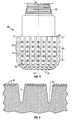
- a drill bit 10 including a substantially cylindrical bit body 12, which defines an axis of rotation 16.
- the shape of the bit with respect to the axis 16 will be further explained.
- the drill bit 10 includes a tapered, threaded connection 22 that may join the bit 10 to a bottom hole assembly ("BHA" - not shown in Figure 1) used to drill a wellbore (not shown in Figure 1).
- BHA bottom hole assembly
- the threaded connection 22 is well known in the art and may differ in appearance from the embodiment shown in Figure 3.
- the connection 22 may also be a box connection (as shown in Figure 7).
- the bit 10 in this embodiment includes a plurality of channels 18 that are formed or milled into the bit surface 24 during manufacturing.
- the channels 18 provide fluid passages for the flow of drilling fluids into and out of the wellbore.
- the flow of drilling fluids assists in the removal of cuttings from the wellbore and help reduce the high temperatures experienced when drilling a wellbore.
- Drilling fluid may be provided to the wellbore through nozzles (not shown) disposed proximate the channels 18, although typical impregnated bits such as the embodiment shown in Figure 3 typically include an area referred to as a "crows foot" (not shown separately in Figure 3) where the drilling fluid passes from inside the bit to the bit surface.
- Nozzles (not shown), if used in any embodiment of a bit made according to the invention, may also be disposed on other portions of the bit 10.
- the channels 18 that cross the surface 24 of the bit body 12 define a plurality of blades 14.
- the blades 14 may be of any shape known in the art, such as helically formed with respect to the axis 16, or straight (substantially parallel to the axis 16). In the embodiment shown in Figure 3, the blades 14 are straight, and define a substantially right-cylindrical surface, meaning that the defined surface is substantially parallel to the axis 16. However, this aspect of the blade shape is not meant to limit the invention.
- the blades 14 may alternatively define a surface having a diameter substantially less than a drill diameter proximate a lower surface of the bit 10 and taper, defining a gradually increasing diameter, to the full drill diameter at a selected axial position along the bit 10.
- the blades 14 may also taper axially in the opposite manner.
- An important aspect of a bit made according to the invention is the drill diameter defined by the blades. The defined drill diameter will be further explained.
- the bit 10 and the blades 14 are manufactured from a base matrix material.
- the bit 10 is typically formed through a powder metallurgy process in which abrasive particles 30 are added to the base matrix material to form an impregnated bit 10. While Figure 3 shows an example of the abrasive particles 30 located on a limited region of the bit surface 24, the abrasive particles 30 are typically located throughout the surface 24 of the drill bit 10.
- the bit 10 may also include abrasive inserts, shown generally at 20, disposed generally in the surface of the blades 14.
- the inserts 20 include abrasive particles, which may be synthetic or natural diamond, boron nitride, or any other hard or superhard material.
- Figure 4 shows the abrasive particles 30 located at and beneath the surface of one of the blades 14.
- the abrasive particles 30 are present throughout the entire thickness of the blades 14.
- the abrasive particles 30 are typically made from synthetic diamond, natural diamond, boron nitride, or other superhard material.
- the abrasive particles 30 can effectively drill a hole in very hard or abrasive formations and tolerate high rotational speeds.
- the abrasive particles 30 disposed at and below the surface of the blades 14 are advantageous because, unlike surface mounted cutters, the abrasive particles 30 are embedded in the matrix surface 24 of the bit 10.
- the abrasive particles 30 are durable and are less likely to exhibit premature wear than surface set cutters.
- the embedded abrasive particles 30 are less likely to be sheared off or "popped out" of the bit 10 than are comparable surface set cutters. Even as the particles 30 drop off as the blades 14 wear, new particles 30 will be continually exposed because they are preferably disposed throughout the thickness of the blades 14, maintaining the cutting ability of the blades 14.
- the abrasive particles 30 in this embodiment comprise a size range of approximately 250-300 stones per carat (while comparable surface set diamonds comprise a size range of approximately 2-6 stones per carat). However, in other embodiments, larger abrasive particles may also be used, for example in a size range of 4-5 stones per carat. Accordingly, the abrasive particle 30 size is not meant to limit the invention.
- the bit 10 as shown in Figure 3 rotates about the bit axis of rotation 16 during drilling operations.
- the bit drills a hole having the drill diameter.
- the pass through diameter of the bit 10 is smaller than the drill diameter because of the preferred shape of the blades 14.
- the construction of the bit 10 is better illustrated in Figures 5 and 6.
- the axis 16 is substantially coaxial with the bit body 12 and with the threaded connection 22.
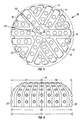
- the drill diameter of the bit D1 is defined by twice a larger radius of curvature R1 of the blades disposed on one side 33 of the bit.
- the bit 10 can be machined so that the laterally outermost surface of the blades 14 disposed on the one side 33 substantially conform to the larger radius R1.
- Diameter D2 which is the sum of radii R1 and R2 and is smaller than twice R1, is equal to the pass through diameter of the bit 10.
- the pass through diameter D2 is the smallest diameter opening through which the bit may freely pass. Therefore, a bit made according to the invention may be passed through a wellbore or casing with a pass through diameter D2, and then drill out formations below the casing or at a selected depth at the full drill diameter D1.
- the blades 14 may extend, at least on the side of the bit where they conform to the full extent of the larger radius, along a substantial axial length in the direction of the threaded connection (22 in Figure 3).
- the portion of the blades 14 which conform to the full extent of their respective radii is shown in Figure 3 at 14A.
- This portion of the blades is known as the gage portion.
- This feature of extended axial length of the gage portion 14A is known as "extended gage”.
- the extended gage is preferably included on the blades 14 on both sides (33, 32 in Figure 6) of the bit, but at least the extended gage should be on the blades on the side (33 in Figure 6) which conforms to the full drill radius (R1 in Figure 6).
- the gage portion of the blades 14, if used in any bit according to the invention, may or may not include abrasive particles (30 in Figure 3) in the structure of that portion of the blades 14.
- the axial length of the extended gage portion is at least 60 percent of the drill diameter D1.
- the gage portion of at least one of the blades 14, and preferably all of the blades 14 includes the abrasive particles 30 impregnated therein to improve the gage protection of a bit according to the invention.
- Other embodiments may include only the inserts for gage protection, having the particles in the blades only on the lower (cutting) end of the bit.
- smaller radius R2 is smaller than larger radius R1 is exaggerated in Figures 5 and 6 to clarify the explanation of the invention.
- the smaller radius R2 may be substantially different than what is shown in Figures 5 and 6 in any particular bit made according to this aspect of the invention.
- the smaller radius R2, in combination with the larger radius R1, defines asymmetry of a bit according to the invention.
- the asymmetry of the bit 10 does not materially adversely affect bit stability during drilling.
- Other embodiments of the invention further improve stability as compared to prior art bits.
- one particular embodiment of the bit 10 is mass balanced such that the center of mass of the bit 10 is located within 1 percent of the drill diameter D1 from the axis of rotation 16. More preferably, the bit 10 is mass balanced so that the center of mass is located within 0.1 percent of the drill diameter D1.
- Mass balancing may be achieved through several methods. For example, the width and depth of the channels 18 may be varied or modified to achieve the desired mass balance. Other methods of balancing are known in the art.
- the more balanced embodiments of the bit 10 stay better centered in the wellbore while drilling, and have less tendency to deviate from any selected wellbore trajectory during drilling.
- the bit according to the invention does not experience instability from rotating about an axis other than a centerline of the bit body.
- Another aspect of the invention is a preferred range of a contact angle A (shown in Figure 5) of the bit 10 with the formation (not shown) being drilled.
- the contact angle A ultimately defines the contact area between the blades on the side 33 of the bit defining the larger radius (R1 in Figure 6) and correspondingly the drill diameter (D1 in Figure 6).
- the contact angle A according to this aspect of the invention should be as large as possible, to make blade contact with the formations being drilled over as large an area as possible.
- the contact angle A in this aspect of the invention is typically about 140 to 180 degrees. Specifically, in one embodiment, the contact angle A is about 140 to 160 degrees. In another embodiment of a bit according to this aspect of the invention, the contact angle A is about 160 to 180 degrees. These are generally larger contact angles than used in prior art asymmetric bits.
- the large contact angle A enables the bit 10 according to the invention to more efficiently drill a gage wellbore and can reduce wear on the bit because of a larger drill area.
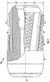
- FIG. 7 Another embodiment of a bit 40 according to the invention is shown in Figure 7 and includes a bit body 42 and a gage sleeve 43.
- the bit body 42 shown in Figure 7 has not yet been finished to include channels, blades, gage protection elements, etc. for clarity of the illustration. However, on being finished, the bit body 42 can be formed to create a bit according to any embodiment of the bit described previously herein.
- the bit body 42 in this aspect of the invention may also be finish formed into a symmetric impregnated bit as known in the prior art.
- the bit body 42 can be attached to the gage sleeve 43 by any suitable means known in the art.
- the gage sleeve 43 in this embodiment includes blades 44, grooves 48, and slots 46.
- the slots 46 are included to enable the bit 40 to be connected to a BHA (not shown) wherein the slots 46 provide gripping spaces for rig tongs (not shown) used to make up the sleeve 43 to the BHA (not shown) in a manner well known in the art.
- the grooves 48 provide pathways for drilling fluid circulation.
- the blades 44 in this embodiment include a plurality of gage protection elements 50.
- the gage protection elements 50 protect the gage sleeve 43 from excessive wear.
- the gage sleeve 43 may include a box (female) connection, as shown at 54, for threaded coupling to the BHA (not shown).
- the gage sleeve 43 serves to further stabilize the bit 40 in the wellbore during drilling.
- the gage sleeve 43 may have blades 44 which are symmetric with respect to the axis 52, or may be asymmetric in a manner similar to the bit body 42 when the bit body 42 is formed according to previous embodiments of the invention.
- the embodiment of the gage sleeve 43 shown in Figure 7 may be formed so that the blades 46 conform to two different radii R3 and R4.
- the blades 46 are formed on one side of the sleeve 43 so that radius R4 defined by these blades is smaller than radius R3 defined by the blades 46 on the other side of the sleeve 43.
- the smaller radius R4 of the gage sleeve 43 is preferably azimuthally aligned with the smaller radius (not shown) of the bit body 42 when the bit body is made according to previous embodiments of the invention.
- the pass through diameter of the gage sleeve 43 thus formed which is the sum of radii R3 and R4, may be substantially the same diameter as the pass through diameter (D2 in Figure 6) of the bit body 42.
- the gage sleeve 43 may also have a smaller pass through diameter than the pass through diameter D2 of the bit. In either configuration, the gage sleeve 43 serves to stabilize the bit and 40 to help maintain the selected drilling trajectory.
- FIG 8. An asymmetric bit 62, as described in previous embodiments, is shown with a stabilizer 64 located axially above the bit 62 on a bottom hole assembly 60.
- the stabilizer 64 serves to further centralize the bit 62 in a wellbore.
- the stabilizer 64 may be asymmetric or symmetric. Asymmetry, when the stabilizer is so formed, is provided in the same manner as previously described for the gage sleeve (43 in Figure 7). If the stabilizer 64 is asymmetric, the side of the stabilizer which defines the smaller radius is preferably azimuthally aligned with the side of the bit 62 which defines the smaller radius.
- the smaller radius side of the stabilizer 64 may be azimuthally positioned at any azimuthal position relative to the smaller radius side of the bit 62.
- the stabilizer 64 may have a gage diameter (defined as twice the larger radius) which is substantially the same as the pass through diameter of the asymmetric bit 62.
- the stabilizer 64 may also have a gage diameter smaller than the pass through diameter of the asymmetric bit 62.
- the stabilizer 64 may include channels 66 and blades 68 similar to the channels and blades of the gage sleeve (43 in Figure 6) of the previous embodiment.
- the blades 68 and channels 66 may be tapered, helically formed, or straight.
- the blades 68 may be provided with inserts 70 that protect the stabilizer 64 from excessive wear.
- the blades 68 may also be surfaced with a wear resistant coating of any type well known in the art.
- the threaded connection is shown as a "pin” (male threaded connection).
- the threaded connection is a "box” (female threaded connection).
- the invention presents a solution to increasing the life and efficiency of diamond impregnated drill bits. Because the asymmetry of the bit is formed by forming one side of the bit to define a smaller radius, the stability of the bit is not compromised. This configuration has advantages over prior art bits that drill a hole larger than the pass through diameter of the bit by offsetting the axis of rotation or the threaded connection. Offsetting the axis or the threaded connection may adversely affect the stability of the bit or reduce the size and strength of the threaded connection.
- the bit according to the invention can be more efficient than prior art bits bit.
- the larger contact surface can be especially useful when drilling very hard and abrasive formations.
Landscapes
- Engineering & Computer Science (AREA)
- Geology (AREA)
- Life Sciences & Earth Sciences (AREA)
- Mining & Mineral Resources (AREA)
- Physics & Mathematics (AREA)
- Environmental & Geological Engineering (AREA)
- Fluid Mechanics (AREA)
- Mechanical Engineering (AREA)
- General Life Sciences & Earth Sciences (AREA)
- Geochemistry & Mineralogy (AREA)
- Processing Of Stones Or Stones Resemblance Materials (AREA)
- Polishing Bodies And Polishing Tools (AREA)
- Drilling Tools (AREA)
- Earth Drilling (AREA)
Claims (27)
- Bohrkopf (10), umfassend:einen Bohrkopfkörper (12), welcher angeordnet ist, um an wenigstens einem distalen Ende des Bohrkopfes (10) zu bohren; undeine Mehrzahl von Schneidelementen (14), welche im Bohrkopfkörper (12) wenigstens teilweise aus infiltriertem Feststoffmatrixmaterial ausgebildet sind, wobei die Schneidelemente (14) Schleifpartikel (30) aufweisen, die darauf abgelagert sind,wobei in Bezug auf eine Rotationsachse (16) des Bohrkopfs (10) im Wesentlichen die gesamte eine Seite (32) des Bohrkopfkörpers (12) mit einem zweiten Radius (R2) ausgebildet ist und im Wesentlichen die gesamte gegenüberliegende Seite (33) des Bohrkopfkörpers (12) mit einem ersten Radius (R1) ausgebildet ist, der größer als der Radius (R2) ist, so dass der Bohrkopf (10) ein Loch größeren Durchmessers (D1) als ein Durchziehdurchmesser (D2) des Bohrkopfs (10) bohrt,wobei die Mehrzahl der Schneidelemente (14) um einen Umfang des Bohrkopfkörpers (12) befestigt ist.
- Bohrkopf (10) gemäß Anspruch 1, wobei Schleifeinsätze (20) an wenigstens einem der Schneidelemente (14) angeordnet sind.
- Bohrkopf (10) gemäß Anspruch 2, wobei die Einsätze (20) um den gesamten Umfang des Bohrkopfkörpers (12) angeordnet sind.
- Bohrkopf (10) gemäß Anspruch 2, wobei die Einsätze (20) wenigstens eines aus der Gruppe synthetischer Diamant, natürlicher Diamant und Bornitrid umfassen.
- Bohrkopf (10) gemäß Anspruch 1, wobei der Bohrkopf (10) massenausgewuchtet ist, so dass ein Massenschwerpunkt des Bohrkopfs innerhalb 1 Prozent eines Bohrdurchmessers von einer Bohrkopfrotationsachse (16) liegt.
- Bohrkopf (10) gemäß Anspruch 1, wobei ein Stabilisator (64) axial über dem Bohrkopfkörper (12) in einer Imlochanordnung (60) positioniert ist.
- Bohrkopf (10) gemäß Anspruch 6, wobei in Bezug auf die Rotationsachse (16) der Stabilisator (64) eine Seite umfasst, die mit einem Radius kleiner als eine gegenüberliegende Seite des Stabilisators (64) ausgebildet ist.
- Bohrkopf (10) gemäß Anspruch 6, wobei der Stabilisator (64) einen Durchmesser aufweist, welcher geringer als der oder im Wesentlichen gleich dem Durchziehdurchmesser des Bohrkopfs (10) ist.
- Bohrkopf (10) gemäß Anspruch 1, des Weiteren umfassend eine Muffenverbindung, welche in einem Verbindungsende des Bohrkopfkörpers (12) ausgebildet ist.
- Bohrkopf (10) gemäß Anspruch 6, wobei der Stabilisator (64) des Weiteren umfasst:eine Mehrzahl von Schneidelementen (68); undeine Mehrzahl von Einsätzen (70), welche auf den Stabilisatorschneidelementen (68) angeordnet sind.
- Bohrkopf (10) gemäß Anspruch 10, wobei die Einsätze (70) auf dem Stabilisator (64) wenigstens eines aus der Gruppe synthetischer Diamant, natürlicher Diamant und Bornitrid umfassen.
- Bohrkopf (10) gemäß Anspruch 1, wobei die Schleifpartikel (30) einen Maßabschnitt (14A) von wenigstens einem der Schneidelemente (14) besetzen, um dessen Maßsicherung zu verbessern.
- Bohrkopf (10) gemäß Anspruch 1, des Weiteren umfassend:eine Maßmanschette (43), welche am Bohrkopfkörper (12) an einem Verbindungsende des Bohrkopfkörpers (12) angebracht ist.
- Bohrkopf (10) gemäß Anspruch 13, wobei in Bezug auf die Rotationsachse (16) die Maßmanschette (43) eine Seite umfasst, welche mit einem Radius (R4) kleiner als ein Radius einer gegenüberliegenden Seite der Maßmanschette (43) ausgebildet ist.
- Bohrkopf gemäß Anspruch 13, wobei die Maßmanschette (43) so positioniert ist, dass die kleinere Radiusseite (R4) der Maßmanschette (43) und die kleinere Radiusseite (R2) des Bohrkopfkörpers (12) im Wesentlichen azimuthal gefluchtet sind.
- Bohrkopf (10) gemäß Anspruch 13, wobei die Maßmanschette (43) entfernbar an dem Bohrkopfkörper (12) angebracht ist.
- Bohrkopf (10) gemäß Anspruch 13, wobei die Maßmanschette (43) einen Durchmesser aufweist, welcher geringer als der oder im Wesentlichen gleich dem Durchziehdurchmesser des Bohrkopfs (10) ist.
- Bohrkopf (10) gemäß Anspruch 13, wobei der Bohrkopf (10) und die Maßmanschette (43) massenausgewuchtet sind, so dass ein Schwerpunkt des Bohrkopfs (10) und der Maßmanschette (43) innerhalb 1 Prozent eines Bohrdurchmessers des Bohrkopfs (10) von der Rotationsachse (16) liegt.
- Bohrkopf (10) gemäß Anspruch 13, wobei die Maßmanschette (43) des Weiteren eine Mehrzahl von Maßsicherungseinsätzen (50) umfasst, welche an den Schneidelementen (14) davon angeordnet sind.
- Bohrkopf (10) gemäß Anspruch 19, wobei die Einsätze (50) auf der Maßmanschette (43) wenigstens eines aus der Gruppe synthetischer Diamant, natürlicher Diamant und Bornitrid umfassen.
- Bohrkopf (10) gemäß Anspruch 13, wobei die Maßmanschette (43) eine Muffenverbindung an einem Ende davon, gegenüberliegend dem Verbindungsende des Bohrkopfkörpers (12), umfasst.
- Bohrkopf gemäß Anspruch 1, wobei
die Schneidelemente (14) an der gegenüberliegende Seite (33) des Bohrkopfkörpers (12) einen Kontaktwinkel (A) von wenigstens 140 Grad definieren. - Bohrkopf (10) gemäß den Ansprüchen 1, 13 oder 22, wobei die Schneidelemente (14) an wenigstens der gegenüberliegenden Seite (33) des Bohrkopfkörpers (12) eine axiale Länge von wenigstens 60 Prozent des Durchmessers (D1) eines Lochs, welches durch den Bohrkopf (10) gebohrt wird, aufweisen, wo die Schneidelemente (14) gemäß jeweils einem der Radien ausgebildet sind.
- Bohrkopf (10) gemäß den Ansprüchen 1, 13 oder 22, wobei die axiale Längsausdehnung wenigstens 60 Prozent eines Bohrdurchmessers des Bohrkopfs (10) an der einen Seite (32) des Bohrkopfkörpers (12) ausmacht.
- Bohrkopf (10) gemäß den Ansprüchen 1, 13 oder 22, wobei die Schleifpartikel (30) Partikel umfassen, welche in die Schneidelemente (14) eingebracht sind.
- Bohrkopf (10) gemäß den Ansprüchen 1, 13 oder 22, wobei die Schleifpartikel (30) wenigstens eines aus der Gruppe synthetischer Diamant, natürlicher Diamant und Bornitrid umfassen.
- Bohrkopf (10) gemäß den Ansprüchen 1, 13 oder 22, des Weiteren umfassend wenigstens einen Maßsicherungseinsatz (50), welcher an einem Maßabschnitt (14A) des wenigstens einen der Schneidelemente (14) angeordnet ist.
Applications Claiming Priority (2)
| Application Number | Priority Date | Filing Date | Title |
|---|---|---|---|
| US619742 | 2000-07-19 | ||
| US09/619,742 US6474425B1 (en) | 2000-07-19 | 2000-07-19 | Asymmetric diamond impregnated drill bit |
Publications (3)
| Publication Number | Publication Date |
|---|---|
| EP1174584A2 EP1174584A2 (de) | 2002-01-23 |
| EP1174584A3 EP1174584A3 (de) | 2002-11-27 |
| EP1174584B1 true EP1174584B1 (de) | 2006-03-01 |
Family
ID=24483115
Family Applications (1)
| Application Number | Title | Priority Date | Filing Date |
|---|---|---|---|
| EP01117366A Expired - Lifetime EP1174584B1 (de) | 2000-07-19 | 2001-07-18 | Asymmetrischer diamantimprägnierter Bohrmeissel |
Country Status (3)
| Country | Link |
|---|---|
| US (1) | US6474425B1 (de) |
| EP (1) | EP1174584B1 (de) |
| DE (1) | DE60117435T2 (de) |
Families Citing this family (138)
| Publication number | Priority date | Publication date | Assignee | Title |
|---|---|---|---|---|
| US7562725B1 (en) * | 2003-07-10 | 2009-07-21 | Broussard Edwin J | Downhole pilot bit and reamer with maximized mud motor dimensions |
| US9428822B2 (en) | 2004-04-28 | 2016-08-30 | Baker Hughes Incorporated | Earth-boring tools and components thereof including material having hard phase in a metallic binder, and metallic binder compositions for use in forming such tools and components |
| US20050211475A1 (en) | 2004-04-28 | 2005-09-29 | Mirchandani Prakash K | Earth-boring bits |
| US7513320B2 (en) | 2004-12-16 | 2009-04-07 | Tdy Industries, Inc. | Cemented carbide inserts for earth-boring bits |
| US8637127B2 (en) | 2005-06-27 | 2014-01-28 | Kennametal Inc. | Composite article with coolant channels and tool fabrication method |
| US7687156B2 (en) | 2005-08-18 | 2010-03-30 | Tdy Industries, Inc. | Composite cutting inserts and methods of making the same |
| US7776256B2 (en) | 2005-11-10 | 2010-08-17 | Baker Huges Incorporated | Earth-boring rotary drill bits and methods of manufacturing earth-boring rotary drill bits having particle-matrix composite bit bodies |
| US8002052B2 (en) * | 2005-09-09 | 2011-08-23 | Baker Hughes Incorporated | Particle-matrix composite drill bits with hardfacing |
| US7703555B2 (en) | 2005-09-09 | 2010-04-27 | Baker Hughes Incorporated | Drilling tools having hardfacing with nickel-based matrix materials and hard particles |
| US7597159B2 (en) | 2005-09-09 | 2009-10-06 | Baker Hughes Incorporated | Drill bits and drilling tools including abrasive wear-resistant materials |
| US7997359B2 (en) | 2005-09-09 | 2011-08-16 | Baker Hughes Incorporated | Abrasive wear-resistant hardfacing materials, drill bits and drilling tools including abrasive wear-resistant hardfacing materials |
| US8770324B2 (en) | 2008-06-10 | 2014-07-08 | Baker Hughes Incorporated | Earth-boring tools including sinterbonded components and partially formed tools configured to be sinterbonded |
| US7807099B2 (en) | 2005-11-10 | 2010-10-05 | Baker Hughes Incorporated | Method for forming earth-boring tools comprising silicon carbide composite materials |
| US7802495B2 (en) | 2005-11-10 | 2010-09-28 | Baker Hughes Incorporated | Methods of forming earth-boring rotary drill bits |
| US8522897B2 (en) | 2005-11-21 | 2013-09-03 | Schlumberger Technology Corporation | Lead the bit rotary steerable tool |
| US7497279B2 (en) | 2005-11-21 | 2009-03-03 | Hall David R | Jack element adapted to rotate independent of a drill bit |
| US8205688B2 (en) | 2005-11-21 | 2012-06-26 | Hall David R | Lead the bit rotary steerable system |
| US8316964B2 (en) | 2006-03-23 | 2012-11-27 | Schlumberger Technology Corporation | Drill bit transducer device |
| US8225883B2 (en) | 2005-11-21 | 2012-07-24 | Schlumberger Technology Corporation | Downhole percussive tool with alternating pressure differentials |
| US7419018B2 (en) | 2006-11-01 | 2008-09-02 | Hall David R | Cam assembly in a downhole component |
| US8267196B2 (en) | 2005-11-21 | 2012-09-18 | Schlumberger Technology Corporation | Flow guide actuation |
| US7753144B2 (en) | 2005-11-21 | 2010-07-13 | Schlumberger Technology Corporation | Drill bit with a retained jack element |
| US7600586B2 (en) | 2006-12-15 | 2009-10-13 | Hall David R | System for steering a drill string |
| US7424922B2 (en) | 2005-11-21 | 2008-09-16 | Hall David R | Rotary valve for a jack hammer |
| US8130117B2 (en) | 2006-03-23 | 2012-03-06 | Schlumberger Technology Corporation | Drill bit with an electrically isolated transmitter |
| US8297378B2 (en) | 2005-11-21 | 2012-10-30 | Schlumberger Technology Corporation | Turbine driven hammer that oscillates at a constant frequency |
| US7641003B2 (en) | 2005-11-21 | 2010-01-05 | David R Hall | Downhole hammer assembly |
| US7419016B2 (en) | 2006-03-23 | 2008-09-02 | Hall David R | Bi-center drill bit |
| US8360174B2 (en) | 2006-03-23 | 2013-01-29 | Schlumberger Technology Corporation | Lead the bit rotary steerable tool |
| US7571780B2 (en) | 2006-03-24 | 2009-08-11 | Hall David R | Jack element for a drill bit |
| US7641002B2 (en) | 2005-11-21 | 2010-01-05 | Hall David R | Drill bit |
| US7549489B2 (en) | 2006-03-23 | 2009-06-23 | Hall David R | Jack element with a stop-off |
| US7484576B2 (en) | 2006-03-23 | 2009-02-03 | Hall David R | Jack element in communication with an electric motor and or generator |
| US8297375B2 (en) | 2005-11-21 | 2012-10-30 | Schlumberger Technology Corporation | Downhole turbine |
| US8528664B2 (en) | 2005-11-21 | 2013-09-10 | Schlumberger Technology Corporation | Downhole mechanism |
| US7559379B2 (en) | 2005-11-21 | 2009-07-14 | Hall David R | Downhole steering |
| US7591327B2 (en) | 2005-11-21 | 2009-09-22 | Hall David R | Drilling at a resonant frequency |
| US7617886B2 (en) | 2005-11-21 | 2009-11-17 | Hall David R | Fluid-actuated hammer bit |
| US7967082B2 (en) | 2005-11-21 | 2011-06-28 | Schlumberger Technology Corporation | Downhole mechanism |
| US7533737B2 (en) | 2005-11-21 | 2009-05-19 | Hall David R | Jet arrangement for a downhole drill bit |
| US7900720B2 (en) | 2006-01-18 | 2011-03-08 | Schlumberger Technology Corporation | Downhole drive shaft connection |
| BRPI0707813A2 (pt) | 2006-02-14 | 2011-05-10 | Smart Stabilizer Systems Ltd | montagem de furo descendente e montagem de cortador |
| EP2004948A2 (de) | 2006-03-17 | 2008-12-24 | Halliburton Energy Services, Inc. | Matrix bohrspitzen mit nach hinten geneigten schneidelementen |
| JP4809711B2 (ja) * | 2006-03-22 | 2011-11-09 | 日本プロジェクト株式会社 | ドリル |
| US7694756B2 (en) | 2006-03-23 | 2010-04-13 | Hall David R | Indenting member for a drill bit |
| US7661487B2 (en) | 2006-03-23 | 2010-02-16 | Hall David R | Downhole percussive tool with alternating pressure differentials |
| USD620510S1 (en) | 2006-03-23 | 2010-07-27 | Schlumberger Technology Corporation | Drill bit |
| RU2432445C2 (ru) | 2006-04-27 | 2011-10-27 | Ти Ди Уай Индастриз, Инк. | Модульное буровое долото с неподвижными режущими элементами, корпус данного модульного бурового долота и способы их изготовления |
| US9316061B2 (en) | 2006-08-11 | 2016-04-19 | David R. Hall | High impact resistant degradation element |
| US8567532B2 (en) | 2006-08-11 | 2013-10-29 | Schlumberger Technology Corporation | Cutting element attached to downhole fixed bladed bit at a positive rake angle |
| US8590644B2 (en) | 2006-08-11 | 2013-11-26 | Schlumberger Technology Corporation | Downhole drill bit |
| US7886851B2 (en) * | 2006-08-11 | 2011-02-15 | Schlumberger Technology Corporation | Drill bit nozzle |
| US7871133B2 (en) | 2006-08-11 | 2011-01-18 | Schlumberger Technology Corporation | Locking fixture |
| US8215420B2 (en) | 2006-08-11 | 2012-07-10 | Schlumberger Technology Corporation | Thermally stable pointed diamond with increased impact resistance |
| US7669674B2 (en) | 2006-08-11 | 2010-03-02 | Hall David R | Degradation assembly |
| US7637574B2 (en) | 2006-08-11 | 2009-12-29 | Hall David R | Pick assembly |
| US8616305B2 (en) | 2006-08-11 | 2013-12-31 | Schlumberger Technology Corporation | Fixed bladed bit that shifts weight between an indenter and cutting elements |
| US8240404B2 (en) | 2006-08-11 | 2012-08-14 | Hall David R | Roof bolt bit |
| US8191651B2 (en) | 2006-08-11 | 2012-06-05 | Hall David R | Sensor on a formation engaging member of a drill bit |
| US9051795B2 (en) | 2006-08-11 | 2015-06-09 | Schlumberger Technology Corporation | Downhole drill bit |
| US8122980B2 (en) | 2007-06-22 | 2012-02-28 | Schlumberger Technology Corporation | Rotary drag bit with pointed cutting elements |
| US8622155B2 (en) | 2006-08-11 | 2014-01-07 | Schlumberger Technology Corporation | Pointed diamond working ends on a shear bit |
| US8449040B2 (en) | 2006-08-11 | 2013-05-28 | David R. Hall | Shank for an attack tool |
| US9145742B2 (en) | 2006-08-11 | 2015-09-29 | Schlumberger Technology Corporation | Pointed working ends on a drill bit |
| US8714285B2 (en) | 2006-08-11 | 2014-05-06 | Schlumberger Technology Corporation | Method for drilling with a fixed bladed bit |
| US20080035389A1 (en) | 2006-08-11 | 2008-02-14 | Hall David R | Roof Mining Drill Bit |
| CA2662966C (en) | 2006-08-30 | 2012-11-13 | Baker Hughes Incorporated | Methods for applying wear-resistant material to exterior surfaces of earth-boring tools and resulting structures |
| US7527110B2 (en) | 2006-10-13 | 2009-05-05 | Hall David R | Percussive drill bit |
| EP2078101A2 (de) | 2006-10-25 | 2009-07-15 | TDY Industries, Inc. | Artikel mit erhöhter widerstandsfähigkeit gegenüber thermischem cracken |
| US9068410B2 (en) | 2006-10-26 | 2015-06-30 | Schlumberger Technology Corporation | Dense diamond body |
| US8960337B2 (en) | 2006-10-26 | 2015-02-24 | Schlumberger Technology Corporation | High impact resistant tool with an apex width between a first and second transitions |
| US7954401B2 (en) | 2006-10-27 | 2011-06-07 | Schlumberger Technology Corporation | Method of assembling a drill bit with a jack element |
| US8272295B2 (en) * | 2006-12-07 | 2012-09-25 | Baker Hughes Incorporated | Displacement members and intermediate structures for use in forming at least a portion of bit bodies of earth-boring rotary drill bits |
| US9506298B2 (en) * | 2013-11-20 | 2016-11-29 | Longyear Tm, Inc. | Drill bits having blind-hole flushing and systems for using same |
| US8459381B2 (en) | 2006-12-14 | 2013-06-11 | Longyear Tm, Inc. | Drill bits with axially-tapered waterways |
| US7392857B1 (en) | 2007-01-03 | 2008-07-01 | Hall David R | Apparatus and method for vibrating a drill bit |
| US8839888B2 (en) | 2010-04-23 | 2014-09-23 | Schlumberger Technology Corporation | Tracking shearing cutters on a fixed bladed drill bit with pointed cutting elements |
| USD678368S1 (en) | 2007-02-12 | 2013-03-19 | David R. Hall | Drill bit with a pointed cutting element |
| USD674422S1 (en) | 2007-02-12 | 2013-01-15 | Hall David R | Drill bit with a pointed cutting element and a shearing cutting element |
| US7846551B2 (en) | 2007-03-16 | 2010-12-07 | Tdy Industries, Inc. | Composite articles |
| US7866416B2 (en) | 2007-06-04 | 2011-01-11 | Schlumberger Technology Corporation | Clutch for a jack element |
| US7967083B2 (en) | 2007-09-06 | 2011-06-28 | Schlumberger Technology Corporation | Sensor for determining a position of a jack element |
| US7721826B2 (en) | 2007-09-06 | 2010-05-25 | Schlumberger Technology Corporation | Downhole jack assembly sensor |
| US8631883B2 (en) * | 2008-03-06 | 2014-01-21 | Varel International Ind., L.P. | Sectorial force balancing of drill bits |
| CA2719752A1 (en) * | 2008-03-31 | 2009-10-08 | Halliburton Energy Services, Inc. | System and method for one-trip hole enlargement operations |
| US8540037B2 (en) | 2008-04-30 | 2013-09-24 | Schlumberger Technology Corporation | Layered polycrystalline diamond |
| US8025107B2 (en) * | 2008-05-15 | 2011-09-27 | Longyear Tm, Inc. | Reamer with polycrystalline diamond compact inserts |
| EP2653580B1 (de) | 2008-06-02 | 2014-08-20 | Kennametal Inc. | Zementierte carbidmetallische Legierungsverbindungen |
| US8790439B2 (en) | 2008-06-02 | 2014-07-29 | Kennametal Inc. | Composite sintered powder metal articles |
| US8327951B2 (en) * | 2008-06-27 | 2012-12-11 | Omni Ip Ltd. | Drill bit having functional articulation to drill boreholes in earth formations in all directions |
| US7849940B2 (en) * | 2008-06-27 | 2010-12-14 | Omni Ip Ltd. | Drill bit having the ability to drill vertically and laterally |
| US8261632B2 (en) | 2008-07-09 | 2012-09-11 | Baker Hughes Incorporated | Methods of forming earth-boring drill bits |
| US8025112B2 (en) | 2008-08-22 | 2011-09-27 | Tdy Industries, Inc. | Earth-boring bits and other parts including cemented carbide |
| US8322465B2 (en) | 2008-08-22 | 2012-12-04 | TDY Industries, LLC | Earth-boring bit parts including hybrid cemented carbides and methods of making the same |
| US20100181116A1 (en) * | 2009-01-16 | 2010-07-22 | Baker Hughes Incororated | Impregnated drill bit with diamond pins |
| GB0904791D0 (en) * | 2009-03-20 | 2009-05-06 | Turbopower Drilling Sal | Downhole drilling assembly |
| US8701799B2 (en) | 2009-04-29 | 2014-04-22 | Schlumberger Technology Corporation | Drill bit cutter pocket restitution |
| US8272816B2 (en) | 2009-05-12 | 2012-09-25 | TDY Industries, LLC | Composite cemented carbide rotary cutting tools and rotary cutting tool blanks |
| US8191657B2 (en) * | 2009-05-28 | 2012-06-05 | Baker Hughes Incorporated | Rotary drag bits for cutting casing and drilling subterranean formations |
| US8201610B2 (en) | 2009-06-05 | 2012-06-19 | Baker Hughes Incorporated | Methods for manufacturing downhole tools and downhole tool parts |
| US20110000718A1 (en) * | 2009-07-02 | 2011-01-06 | Smith International, Inc. | Integrated cast matrix sleeve api connection bit body and method of using and manufacturing the same |
| US8308096B2 (en) | 2009-07-14 | 2012-11-13 | TDY Industries, LLC | Reinforced roll and method of making same |
| US8911474B2 (en) | 2009-07-16 | 2014-12-16 | Howmedica Osteonics Corp. | Suture anchor implantation instrumentation system |
| WO2011017625A2 (en) * | 2009-08-07 | 2011-02-10 | Smith International, Inc. | Method of forming a thermally stable diamond cutting element |
| CA2770308C (en) * | 2009-08-07 | 2017-11-28 | Smith International, Inc. | Diamond transition layer construction with improved thickness ratio |
| WO2011017607A2 (en) | 2009-08-07 | 2011-02-10 | Smith International, Inc. | Highly wear resistant diamond insert with improved transition structure |
| CN102648328B (zh) * | 2009-08-07 | 2015-02-18 | 史密斯国际有限公司 | 具有高的韧度和高的耐磨性的多晶金刚石材料 |
| CA2770306A1 (en) * | 2009-08-07 | 2011-02-10 | Smith International, Inc. | Functionally graded polycrystalline diamond insert |
| US20110036643A1 (en) * | 2009-08-07 | 2011-02-17 | Belnap J Daniel | Thermally stable polycrystalline diamond constructions |
| CA2812775C (en) | 2009-08-20 | 2015-09-29 | Howmedica Osteonics Corp. | Flexible acl instrumentation, kit and method |
| US9643236B2 (en) | 2009-11-11 | 2017-05-09 | Landis Solutions Llc | Thread rolling die and method of making same |
| US8550190B2 (en) | 2010-04-01 | 2013-10-08 | David R. Hall | Inner bit disposed within an outer bit |
| US8418784B2 (en) | 2010-05-11 | 2013-04-16 | David R. Hall | Central cutting region of a drilling head assembly |
| WO2011146760A2 (en) | 2010-05-20 | 2011-11-24 | Baker Hughes Incorporated | Methods of forming at least a portion of earth-boring tools, and articles formed by such methods |
| RU2012155101A (ru) | 2010-05-20 | 2014-06-27 | Бейкер Хьюз Инкорпорейтед | Способы формирования по меньшей мере части бурильного инструмента |
| EP2571647A4 (de) | 2010-05-20 | 2017-04-12 | Baker Hughes Incorporated | Verfahren zur formung mindestens eines teils eines erdbohrwerkzeugs und in diesen verfahren geformte artikel |
| US8820440B2 (en) | 2010-10-01 | 2014-09-02 | David R. Hall | Drill bit steering assembly |
| US8333254B2 (en) | 2010-10-01 | 2012-12-18 | Hall David R | Steering mechanism with a ring disposed about an outer diameter of a drill bit and method for drilling |
| US20120192680A1 (en) * | 2011-01-27 | 2012-08-02 | Baker Hughes Incorporated | Fabricated Mill Body with Blade Pockets for Insert Placement and Alignment |
| US8342266B2 (en) | 2011-03-15 | 2013-01-01 | Hall David R | Timed steering nozzle on a downhole drill bit |
| US9795398B2 (en) | 2011-04-13 | 2017-10-24 | Howmedica Osteonics Corp. | Flexible ACL instrumentation, kit and method |
| US8800848B2 (en) | 2011-08-31 | 2014-08-12 | Kennametal Inc. | Methods of forming wear resistant layers on metallic surfaces |
| US9016406B2 (en) | 2011-09-22 | 2015-04-28 | Kennametal Inc. | Cutting inserts for earth-boring bits |
| US20130112484A1 (en) * | 2011-11-04 | 2013-05-09 | Shilin Chen | Eccentric sleeve for directional drilling systems |
| US9445803B2 (en) | 2011-11-23 | 2016-09-20 | Howmedica Osteonics Corp. | Filamentary suture anchor |
| US9808242B2 (en) | 2012-04-06 | 2017-11-07 | Howmedica Osteonics Corp. | Knotless filament anchor for soft tissue repair |
| US8821494B2 (en) | 2012-08-03 | 2014-09-02 | Howmedica Osteonics Corp. | Surgical instruments and methods of use |
| US9078740B2 (en) | 2013-01-21 | 2015-07-14 | Howmedica Osteonics Corp. | Instrumentation and method for positioning and securing a graft |
| US9402620B2 (en) | 2013-03-04 | 2016-08-02 | Howmedica Osteonics Corp. | Knotless filamentary fixation devices, assemblies and systems and methods of assembly and use |
| WO2014176270A1 (en) | 2013-04-22 | 2014-10-30 | Pivot Medical, Inc. | Method and apparatus for attaching tissue to bone |
| US9469015B2 (en) | 2013-07-08 | 2016-10-18 | Varel International, Ind., L.P. | Impregnated rotary bit with high density monoblock center structure |
| US9986992B2 (en) | 2014-10-28 | 2018-06-05 | Stryker Corporation | Suture anchor and associated methods of use |
| CN105952382A (zh) * | 2016-06-28 | 2016-09-21 | 四川川庆石油钻采科技有限公司 | 一种具有双切削结构孕镶金刚石钻头 |
| US10494875B2 (en) | 2017-01-13 | 2019-12-03 | Baker Hughes, A Ge Company, Llc | Impregnated drill bit including a planar blade profile along drill bit face |
| WO2018169741A1 (en) | 2017-03-17 | 2018-09-20 | Baker Hughes, A Ge Company, Llc | Earth-boring tools with reduced vibrational response and related methods |
| US11098541B2 (en) * | 2018-03-16 | 2021-08-24 | Ulterra Drilling Technologies, L.P. | Polycrystalline-diamond compact air bit |
| USD991993S1 (en) * | 2020-06-24 | 2023-07-11 | Sumitomo Electric Hardmetal Corp. | Cutting tool |
| CN113882800A (zh) * | 2021-08-27 | 2022-01-04 | 上海市基础工程集团有限公司 | 可拆卸式潜水钻机保径装置 |
Citations (3)
| Publication number | Priority date | Publication date | Assignee | Title |
|---|---|---|---|---|
| US2953354A (en) * | 1958-05-15 | 1960-09-20 | Edward B Williams Iii | Drill bit |
| US3159224A (en) * | 1960-12-30 | 1964-12-01 | Atlantic Refining Co | Underdrilling rotary bit |
| US4635738A (en) * | 1984-04-14 | 1987-01-13 | Norton Christensen, Inc. | Drill bit |
Family Cites Families (15)
| Publication number | Priority date | Publication date | Assignee | Title |
|---|---|---|---|---|
| US3367430A (en) * | 1966-08-24 | 1968-02-06 | Christensen Diamond Prod Co | Combination drill and reamer bit |
| US4266621A (en) * | 1977-06-22 | 1981-05-12 | Christensen, Inc. | Well casing window mill |
| US4274769A (en) * | 1978-04-21 | 1981-06-23 | Acker Drill Company, Inc. | Impregnated diamond drill bit construction |
| US4234048A (en) * | 1978-06-12 | 1980-11-18 | Christensen, Inc. | Drill bits embodying impregnated segments |
| US5373900A (en) * | 1988-04-15 | 1994-12-20 | Baker Hughes Incorporated | Downhole milling tool |
| US5042596A (en) * | 1989-02-21 | 1991-08-27 | Amoco Corporation | Imbalance compensated drill bit |
| US5649603A (en) * | 1992-05-27 | 1997-07-22 | Astec Developments Limited | Downhole tools having circumferentially spaced rolling elements |
| DE4233770A1 (de) * | 1992-10-07 | 1994-04-14 | Hilti Ag | Verfahren zur Herstellung von Diamantbohrkronen |
| US5992548A (en) * | 1995-08-15 | 1999-11-30 | Diamond Products International, Inc. | Bi-center bit with oppositely disposed cutting surfaces |
| US5904213A (en) * | 1995-10-10 | 1999-05-18 | Camco International (Uk) Limited | Rotary drill bits |
| EP0822318B1 (de) * | 1996-08-01 | 2002-06-05 | Camco International (UK) Limited | Verbesserungen an Drehbohrmeisseln |
| US5957223A (en) * | 1997-03-05 | 1999-09-28 | Baker Hughes Incorporated | Bi-center drill bit with enhanced stabilizing features |
| US6206117B1 (en) * | 1997-04-02 | 2001-03-27 | Baker Hughes Incorporated | Drilling structure with non-axial gage |
| US6123160A (en) * | 1997-04-02 | 2000-09-26 | Baker Hughes Incorporated | Drill bit with gage definition region |
| US6241036B1 (en) * | 1998-09-16 | 2001-06-05 | Baker Hughes Incorporated | Reinforced abrasive-impregnated cutting elements, drill bits including same |
-
2000
- 2000-07-19 US US09/619,742 patent/US6474425B1/en not_active Expired - Lifetime
-
2001
- 2001-07-18 EP EP01117366A patent/EP1174584B1/de not_active Expired - Lifetime
- 2001-07-18 DE DE60117435T patent/DE60117435T2/de not_active Expired - Lifetime
Patent Citations (3)
| Publication number | Priority date | Publication date | Assignee | Title |
|---|---|---|---|---|
| US2953354A (en) * | 1958-05-15 | 1960-09-20 | Edward B Williams Iii | Drill bit |
| US3159224A (en) * | 1960-12-30 | 1964-12-01 | Atlantic Refining Co | Underdrilling rotary bit |
| US4635738A (en) * | 1984-04-14 | 1987-01-13 | Norton Christensen, Inc. | Drill bit |
Also Published As
| Publication number | Publication date |
|---|---|
| DE60117435T2 (de) | 2006-10-12 |
| DE60117435D1 (de) | 2006-04-27 |
| EP1174584A2 (de) | 2002-01-23 |
| EP1174584A3 (de) | 2002-11-27 |
| US6474425B1 (en) | 2002-11-05 |
Similar Documents
| Publication | Publication Date | Title |
|---|---|---|
| EP1174584B1 (de) | Asymmetrischer diamantimprägnierter Bohrmeissel | |
| CA2427254C (en) | Fixed blade fixed cutter hole opener | |
| US6883623B2 (en) | Earth boring apparatus and method offering improved gage trimmer protection | |
| EP1283324B1 (de) | Expandierbares Reibwerkzeug | |
| US8061453B2 (en) | Drill bit with asymmetric gage pad configuration | |
| CA2633493C (en) | Drill bits with bearing elements for reducing exposure of cutters | |
| CN111315955B (zh) | 钻地工具及相关方法 | |
| US20060196699A1 (en) | Modular kerfing drill bit | |
| US20160237752A1 (en) | Subsurface drilling tool | |
| WO2011005774A2 (en) | Backup cutting elements on non-concentric reaming tools | |
| US20110100714A1 (en) | Backup cutting elements on non-concentric earth-boring tools and related methods | |
| WO2013116679A1 (en) | Cutting element retention for high exposure cutting elements on earth-boring tools | |
| US9890597B2 (en) | Drill bits and tools for subterranean drilling including rubbing zones and related methods | |
| EP3775465B1 (de) | Erdbohrwerkzeuge mit festen klingen und drehbaren schneidstrukturen mit unterschiedlichen grössen und zugehörige verfahren | |
| US10954721B2 (en) | Earth-boring tools and related methods | |
| EP3363988B1 (de) | Imprägniertes bohr-bit mit einem planaren blattprofil entlang der bohr-bit-fläche | |
| EP4352333B1 (de) | Erdbohrwerkzeuge mit fluidöffnungen durch die schaufel sowie zugehörige systeme und verfahren | |
| CN112204221A (zh) | 具有固定刀片和可旋转切割结构的钻地工具及相关方法 | |
| AU2021294605B2 (en) | Improved drill bit |
Legal Events
| Date | Code | Title | Description |
|---|---|---|---|
| PUAI | Public reference made under article 153(3) epc to a published international application that has entered the european phase |
Free format text: ORIGINAL CODE: 0009012 |
|
| AK | Designated contracting states |
Kind code of ref document: A2 Designated state(s): AT BE CH CY DE DK ES FI FR GB GR IE IT LI LU MC NL PT SE TR |
|
| AX | Request for extension of the european patent |
Free format text: AL;LT;LV;MK;RO;SI |
|
| RIC1 | Information provided on ipc code assigned before grant |
Free format text: 7E 21B 10/46 A, 7E 21B 10/56 B |
|
| PUAL | Search report despatched |
Free format text: ORIGINAL CODE: 0009013 |
|
| AK | Designated contracting states |
Kind code of ref document: A3 Designated state(s): AT BE CH CY DE DK ES FI FR GB GR IE IT LI LU MC NL PT SE TR |
|
| AX | Request for extension of the european patent |
Free format text: AL;LT;LV;MK;RO;SI |
|
| 17P | Request for examination filed |
Effective date: 20030526 |
|
| AKX | Designation fees paid |
Designated state(s): BE DE FR GB |
|
| 17Q | First examination report despatched |
Effective date: 20030729 |
|
| GRAP | Despatch of communication of intention to grant a patent |
Free format text: ORIGINAL CODE: EPIDOSNIGR1 |
|
| GRAS | Grant fee paid |
Free format text: ORIGINAL CODE: EPIDOSNIGR3 |
|
| GRAA | (expected) grant |
Free format text: ORIGINAL CODE: 0009210 |
|
| AK | Designated contracting states |
Kind code of ref document: B1 Designated state(s): BE DE FR GB |
|
| REG | Reference to a national code |
Ref country code: GB Ref legal event code: FG4D |
|
| REF | Corresponds to: |
Ref document number: 60117435 Country of ref document: DE Date of ref document: 20060427 Kind code of ref document: P |
|
| ET | Fr: translation filed | ||
| PLBE | No opposition filed within time limit |
Free format text: ORIGINAL CODE: 0009261 |
|
| STAA | Information on the status of an ep patent application or granted ep patent |
Free format text: STATUS: NO OPPOSITION FILED WITHIN TIME LIMIT |
|
| 26N | No opposition filed |
Effective date: 20061204 |
|
| PGFP | Annual fee paid to national office [announced via postgrant information from national office to epo] |
Ref country code: GB Payment date: 20120718 Year of fee payment: 12 |
|
| PGFP | Annual fee paid to national office [announced via postgrant information from national office to epo] |
Ref country code: BE Payment date: 20120713 Year of fee payment: 12 Ref country code: FR Payment date: 20120719 Year of fee payment: 12 Ref country code: DE Payment date: 20120711 Year of fee payment: 12 |
|
| BERE | Be: lapsed |
Owner name: *SMITH INTERNATIONAL INC. Effective date: 20130731 |
|
| GBPC | Gb: european patent ceased through non-payment of renewal fee |
Effective date: 20130718 |
|
| REG | Reference to a national code |
Ref country code: FR Ref legal event code: ST Effective date: 20140331 |
|
| PG25 | Lapsed in a contracting state [announced via postgrant information from national office to epo] |
Ref country code: DE Free format text: LAPSE BECAUSE OF NON-PAYMENT OF DUE FEES Effective date: 20140201 Ref country code: BE Free format text: LAPSE BECAUSE OF NON-PAYMENT OF DUE FEES Effective date: 20130731 Ref country code: GB Free format text: LAPSE BECAUSE OF NON-PAYMENT OF DUE FEES Effective date: 20130718 |
|
| REG | Reference to a national code |
Ref country code: DE Ref legal event code: R119 Ref document number: 60117435 Country of ref document: DE Effective date: 20140201 |
|
| PG25 | Lapsed in a contracting state [announced via postgrant information from national office to epo] |
Ref country code: FR Free format text: LAPSE BECAUSE OF NON-PAYMENT OF DUE FEES Effective date: 20130731 |