US8327951B2 - Drill bit having functional articulation to drill boreholes in earth formations in all directions - Google Patents
Drill bit having functional articulation to drill boreholes in earth formations in all directions Download PDFInfo
- Publication number
- US8327951B2 US8327951B2 US12/456,732 US45673209A US8327951B2 US 8327951 B2 US8327951 B2 US 8327951B2 US 45673209 A US45673209 A US 45673209A US 8327951 B2 US8327951 B2 US 8327951B2
- Authority
- US
- United States
- Prior art keywords
- borehole
- drill bit
- cutters
- bit
- region
- Prior art date
- Legal status (The legal status is an assumption and is not a legal conclusion. Google has not performed a legal analysis and makes no representation as to the accuracy of the status listed.)
- Expired - Fee Related, expires
Links
- 230000015572 biosynthetic process Effects 0.000 title description 16
- 238000005755 formation reaction Methods 0.000 title description 16
- 238000005553 drilling Methods 0.000 claims description 45
- 238000005520 cutting process Methods 0.000 claims description 38
- 238000000034 method Methods 0.000 claims 8
- 230000008859 change Effects 0.000 abstract description 4
- 238000010586 diagram Methods 0.000 description 13
- 239000012530 fluid Substances 0.000 description 5
- 238000006073 displacement reaction Methods 0.000 description 2
- 238000005516 engineering process Methods 0.000 description 2
- 230000014759 maintenance of location Effects 0.000 description 2
- 230000007246 mechanism Effects 0.000 description 2
- 230000009471 action Effects 0.000 description 1
- 238000001816 cooling Methods 0.000 description 1
- 229910003460 diamond Inorganic materials 0.000 description 1
- 239000010432 diamond Substances 0.000 description 1
- 238000011010 flushing procedure Methods 0.000 description 1
- 238000003754 machining Methods 0.000 description 1
- 238000004519 manufacturing process Methods 0.000 description 1
- 239000000463 material Substances 0.000 description 1
- 230000035515 penetration Effects 0.000 description 1
- 230000004044 response Effects 0.000 description 1
- 239000011435 rock Substances 0.000 description 1
- 239000007787 solid Substances 0.000 description 1
Images


Classifications
-
- E—FIXED CONSTRUCTIONS
- E21—EARTH DRILLING; MINING
- E21B—EARTH DRILLING, e.g. DEEP DRILLING; OBTAINING OIL, GAS, WATER, SOLUBLE OR MELTABLE MATERIALS OR A SLURRY OF MINERALS FROM WELLS
- E21B10/00—Drill bits
- E21B10/42—Rotary drag type drill bits with teeth, blades or like cutting elements, e.g. fork-type bits, fish tail bits
- E21B10/43—Rotary drag type drill bits with teeth, blades or like cutting elements, e.g. fork-type bits, fish tail bits characterised by the arrangement of teeth or other cutting elements
Definitions
- the present invention relates, generally, to drill bits used for drilling oil and gas wells, and more specifically, to a drill bit capable of drilling in any of a plurality of directions, including backreaming, and drilling oversize boreholes, through a form of functional articulation.
- Drill bits for drilling a borehole within an earth formation are generally well known in the art. Many conventional drill bits are designed to use cutters that include blades having polycrystalline diamond compact (PDC) cutter elements affixed thereon, mounted on a rotary bit, with the PDC cutter elements arranged such that each engages an earth formation at a desired angle. Drill bits are normally cleaned and cooled during drilling by flowing drilling fluid, or mud, from one or more nozzles on the face of the drill bit. Drilling fluid is pumped down the drill string, flows across the bit face, removing cuttings while cooling the bit, then flows back to the surface through the annulus between the drill string and the borehole wall.
- drilling fluid or mud
- Bit 10 is a fixed cutter bit, sometimes referred to as a drag bit or PDC bit, and is adapted for drilling through formations of rock and other earth formations to form a borehole.
- Bit 10 generally includes a bit body having a shank 13 , and a threaded connection or pin 16 for connecting the bit 10 to a drill string (not shown) which is employed to rotate the bit for drilling the borehole.
- Bit 10 further includes a central axis 11 and a cutting structure on the face 14 of the drill bit, which is shown having a plurality of PDC cutter elements 40 disposed thereon.
- a gage pad 12 the outer surface of which is disposed at the diameter of the bit 10 and establishes the bit's size. For example, a 12′′ bit will have the gage pad approximately 6′′ from the center of the bit.
- FIG. 2 depicts a cross-sectional view of the drill bit of FIG. 1 .
- the bit 10 includes a face region 14 and a gage pad region 12 .
- the face region 14 includes a plurality of blades having cutter elements 40 disposed thereon, overlapping in rotated profile. Rotation of the bit 10 causes the cutter elements 40 to drill the borehole as the bit 10 rotates.
- Downwardly extending flow passages 21 are shown extending through the body of the bit 10 , having nozzles or ports 22 disposed at their lowermost ends.
- a conventional bit 10 can include six such flow passages 21 and nozzles 22 .
- the flow passages 21 are in fluid communication with a central bore 17 . Together, the passages 21 and nozzles 22 serve to distribute drilling fluids around the cutter elements 40 for flushing formation cuttings from the bottom of the borehole and away from the cutting faces of cutter elements 40 when drilling.
- gage pads may be used to provide for a borehole having a predictable and constant diameter, it is advantageous at times, to drill a borehole having one or more oversize, or overgauge, regions. This is especially useful during instances where directional drilling or the drilling of highly deviated wellbores is undertaken, as an overgage hole allows for sharper turns.
- the present invention meets these needs.
- the present invention relates, generally, to a drill bit usable to drill a borehole in an earth formation.
- An embodiment of the invention includes a bit body having an end adapted for connection to a tubular drillstring, such as through use of internal or external threads, or a similar type of secure engagement able to withstand the vibrations inherent in drilling without breaking or loosening.
- the opposing end of the bit body includes a bit face having a first plurality of cutters disposed thereon.
- the cutters can include blades having cutter elements, such as PDC cutter elements disposed thereon, however other cutter configurations, such as blades or other protrusions having a cutting surface formed directly thereon, or other types of cutter elements affixed thereto, are also usable.
- the cutting surfaces of the first bit face are oriented to bore through an earth formation in a first direction.
- these cutting surfaces are used to bore in a downhole direction, however in various directional drilling operations, these cutting surfaces can be oriented to face any direction.
- the first plurality of cutters are usable to bore in a direction opposite the drilling string.
- a second bit face is disposed between the ends of the bit body. While the second bit face can be disposed in any relationship with respect to the first bit face, in an embodiment of the invention, the bit body can be a generally cylindrical member, with the first bit face formed along the bottom and the second bit face formed along the lateral surface.
- the second bit face includes a plurality of cutters disposed thereon, these cutters having cutting surfaces oriented to bore in one or more second directions that differ from the direction in which the first bit face bores when rotated.
- the first and second pluralities of cutters enable the drill bit to drill in a manner that is functionally similar to articulation. Through this functional articulation, the drill bit can be maneuvered to drill in any direction, while downhole, without requiring removal of the drill bit from the borehole.
- the first plurality of cutters can be used to bore in a generally downhole direction, while the second plurality of cutters provide an oversize borehole.
- the second plurality of cutters can be oriented to bore in a downhole direction, providing the drill bit with an improved rate of penetration.
- the second plurality of cutters can also be oriented to bore in one or more lateral directions, to backream within the borehole, or combinations thereof.
- the cutting surfaces of the second plurality of cutters can define the outer circumference of the drill bit.
- Conventional drill bits have flattened and/or rounded cutter elements, ground to the desired diameter of the borehole to prevent lateral cutting.
- the present drill bit can present a cutting surface along its outer circumference to enable lateral boring and other changes in drilling direction that would not be possible with a conventional bit.
- an outermost portion of a cutter on the second bit face and an innermost portion of a cutter on the first bit face can be angularly displaced from one another by greater than ninety degrees.
- conventional drill bits include gage retention mechanisms and other devices to restrict the diameter of the borehole and limit the length of the cutting surface
- the present drill bit can include cutters disposed along the shaft of the bit body, providing a cutting radius in excess of ninety degrees. Independent of the angular displacement between cutters, the first and second pluralities of cutters can provide the drill bit with a continuous cutting surface.
- the drill bit can also include a wear ring disposed thereon, having a third plurality of cutters set in a plane perpendicular to the longitudinal axis of the drill bit, the third plurality of cutters defining the outermost circumference of the bit.
- each cutter along the wear ring can be spaced no further from the plane than the cutter diameter.
- One or more additional rings can also be disposed on the drill bit, adjacent to the wear ring, having cutters disposed thereon with a length less than the cutters of the initial wear ring. This configuration enables the wear ring to drill laterally and form a cut in an earth formation, while the cutters on the one or more adjacent rings enlarge the width of the cut.
- embodiments of the present drill bit are usable to change the drilling direction of a borehole.
- a drill bit as described previously, having a first plurality of cutters oriented to bore in a first direction, and a second plurality of cutters oriented to bore in one or more second directions, is provided within a borehole. While within the borehole, a lateral force can be exerted proximate to the drill bit, while the drill bit is rotating, to urge the drill bit in a selected direction. The lateral force causes the second plurality of cutters to bore in the selected direction, thereby changing the drilling direction of the drill bit.
- the lateral force can be exerted using a downhole steerable mud motor, a rotary steerable system, other similar steerable motor systems, or combinations thereof.
- Embodiments of the present drill bit are also usable to produce a borehole having one or more downhole regions with a diameter greater than that of one or more preceding regions.
- a drill bit as described previously, is provided within a borehole, the drill bit having a first plurality of cutters and a second plurality of cutters vertically displaced from one another.
- the first plurality of cutters is oriented to bore in a first direction
- the second plurality of cutters is oriented to bore in one or more second directions, the cutters enabling functional articulation of the drill bit within the borehole, as described above.
- a first region of the borehole is drilled having a first diameter.
- a second region of the borehole, located downhole from the first region, can then be drilled while causing functional articulation of the drill bit, causing the second plurality of cutters to provide the second region of the borehole with a greater diameter.
- the drill bit can then be back reamed through the first region of the borehole without substantially enlarging the diameter of the first region, enabling production of a borehole having an oversized region disposed downhole from a region with a smaller diameter.
- FIG. 1 is a pictorial illustration of a drill bit known in the art
- FIG. 2 is a cross-sectional view of the drill bit of FIG. 1 ;
- FIG. 3 is a pictorial view of an embodiment of the present drill bit
- FIG. 4 is a pictorial bottom view of the drill bit of FIG. 3 ;
- FIG. 5A is a diagram of the orientation of cutter elements disposed along a drill bit known in the art
- FIG. 5B is a diagram of the orientation of the cutter elements disposed along a second drill bit known in the art
- FIG. 5C is a diagram of the orientation of the cutter elements disposed on a cutter of an embodiment of the present drill bit
- FIG. 6 is a cross-sectional view of a directional wellbore drilled with an embodiment of the present drill bit
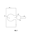
- FIG. 7 is a diagram illustrating the cutting of an external reentrant profile
- FIG. 8 is an upper pictorial view of the drill bit of FIGS. 3 and 4 ;
- FIGS. 9A-9C are diagrams illustrating backrake angles usable to mount cutters in various embodiments of the present drill bit
- FIGS. 10A-10C are diagrams illustrating siderake angles usable to mount cutters in various embodiments of the present drill bit.
- FIG. 11 is a pictorial view of another embodiment of the present drill bit.
- Drill bits manufactured and used according to the preferred embodiments of the present invention being designed to enable functional articulation between the drill bit and the tubular drillstring, are designed to drill in all directions, including forward (downward) in a vertical direction, horizontally, laterally (360°), upward (in a vertical direction,) and at all angels therebetween.
- This major advance in drill bit technology is accomplished, in part, by using cutters having cutting surfaces set in the flank of the bit, in which the backrake angles of such flank-set cutter ing surfaces each provide a drilling edge via a relief angle produced by the backrake angle.
- FIG. 3 depicts a pictorial view of an embodiment of a drill bit 50 according to the present invention.
- the drill bit 50 is shown having a threaded pin end 52 for engaging a drill string (not illustrated).
- the drill bit 50 is further shown having a plurality of blades 54 , 56 , 58 , 59 , 62 , and 64 disposed thereon, each of the blades having a plurality of cutter elements 60 , 61 , 63 , and 65 disposed thereon.
- FIG. 4 depicts a bottom view of the drill bit of FIG. 3 , illustrating the bottom bit face 67 .
- FIG. 8 depicts an upper view of the drill bit of FIGS. 3 and 4 , illustrating the bottom bit face 67 .
- FIG. 8 depicts one or more nozzles 122 , used to flow drilling fluid to clean the drill bit and borehole during use.
- FIG. 5A depicts a diagram of the of the orientation of the cutter elements of a drill bit known in the art, such as the drill bit shown in FIGS. 1 and 2 .
- the diagram shows a bottom bit face 204 having a blade 200 disposed thereon.
- the blade 200 is shown having a plurality of PDC cutter elements 202 disposed thereon.
- the cutting surface provided by the cutter elements 202 begins proximate to the center of the bottom bit face 204 , and extends upward along the side of the bit a short distance, terminating at a wear pad 206 , which is angularly disposed approximately ninety degrees from the bottom of the bit face 204 .
- the depicted orientation of the cutter elements 202 and the wear pad 206 restrict the depicted drill bit to drilling a fixed diameter borehole in a generally downhole direction.
- FIG. 5B depicts a diagram of the of the orientation of the cutter elements of an alternate drill bit known in the art.
- a plurality of PDC cutter elements 214 are shown, beginning proximate to the center of the bottom bit face and extending upward, to terminate at a wear pad 212 angularly displaced approximately ninety degrees from the bottom of the bit face.
- the depicted diagram also includes additional PDC cutter elements 210 oriented to back ream within the borehole. Similar to the diagram of FIG. 5A , the depicted orientation of cutter elements 214 and the wear pad 212 enable the drill bit to drill a fixed diameter borehole in a generally downhole direction.
- the addition of the additional PDC cutter elements 210 enables the drill bit to back ream when pulling the drill bit from the borehole, however only the lower cutter elements 214 are used in the formation of the borehole.
- FIG. 5C depicts a diagram of the orientation of the cutter elements of an embodiment of the present drill bit.
- the drill bit is shown having a blade 220 with cutter elements 222 disposed thereon.
- the cutting surface begins proximate to the center of the bottom bit face 224 and extends upward, along the side of the bit to a selected point 230 . While the angular displacement between the selected point 230 and the center of the bit face 224 can vary, in an embodiment of the invention, the outermost portion of the cutting surface can be angularly displaced from the center of the bit face 224 by greater than ninety degrees, and in further embodiments greater than one hundred degrees, and in still further embodiments greater than one hundred fifteen degrees.
- the depicted arrangement of the cutter elements 222 enables the drill bit to drill not only in a downhole direction, but to also in one or more other directions, including lateral directions, to change the drilling direction of the borehole.
- the upper cutter elements 222 are also usable to back ream from the borehole. Further, the extended cutting surface enables the depicted drill bit to provide an oversize borehole.
- FIG. 6 depicts a cross-sectional view of a directional wellbore able to be drilled using one or more embodiments of the present drill bit.
- a drill bit 50 as described previously, is shown in communication with a drill string 80 , driven by a steerable motor 70 having a “bend” 72 , as is known in the art, attached thereto.
- a drill bit such as the embodiments depicted in FIGS. 3 and 4 , the outermost cutter elements 63 and 65 can smooth out any rough corners otherwise found in angled regions of a borehole, thereby facilitating the placement of casing.
- an orientation system typically having two bends, which enable the drill string to be rotated to a certain orientation
- a “pusher” system that involves pushing the drill string laterally away from its existing location.
- Embodiments of the present drill bit may be used to drill laterally in conjunction with a pusher system. Due to the orientation of the cutters, such as the embodiment illustrated in FIG. 3 , the drill bit can be caused to drill sideways, in a selected lateral direction, under application of a force. Once the drill bit has been oriented to a proper location by pushing, the pusher phase can be discontinued, and the drill bit can continue to be rotated by the motor to continue drilling in a generally straight direction.
- the drill bit can be pulled up by the drill string and thus act somewhat like a reamer to smooth out, back ream, and/or enlarge the borehole as desired.
- the use of a pusher rotary steering system, while rotating the drill bit, allows the bit to drill laterally while the drill string is being pushed. This lateral drilling would be inhibited or impossible using a conventional drill bit lacking the cutter configuration described above. It should be appreciated, however, that the present drill is usable with any rotary steerable system known in the art.
- the drill bit can drill laterally using a rotary steerable system (“RSS”).
- RSS has been introduced in recent years, and is designed to drill directionally, rotating the drill string using a rotary table and/or a top drive, while eliminating the need for a downhole steerable motor.
- Examples of such RSS services are provided by Sperry-Sun Drilling Services (Halliburton); Weatherford; Schlumberger Oilfield Services; and Baker-Hughes Inteq.
- a description of such RSS services is provided in the United States Patent Application having the Publication No. US/2007/0251726 A1, assigned to Schlumberger Oilfield Services of Sugar Land, Tex., the entirety of which is incorporated herein by reference.
- the drill bit can have a cutting surface disposed at and near the diameter of the bit, designed to cut laterally into an earth formation.
- conventional drill bits lack such cutters and/or include a gage pad or flattened/ground cutter elements that inhibit the ability to drill laterally into a formation.
- the cutters mounted at or near the bit diameter enable various backrake and siderake angles.
- FIGS. 9A , 9 B, and 9 C depict a cutter element with cutting surface, and diagrams of various backrake angles.
- FIG. 9A depicts a zero degree backrake, i.e. along a line perpendicular to the formation wall.
- FIG. 9B illustrates a negative twenty degree backrake.
- FIG. 9C illustrates a positive twenty degree backrake.
- the backrake angles chosen for a given drill bit can be determined based on the geology of the formation being drilled and/or the desired aggressive attack angle.
- a typical “normal” backrake for drilling can include a negative backrake range of ⁇ 10° to ⁇ 30°, but can also include a range between +15° to ⁇ 35°.
- a low backrake provides an aggressive attack angle, and thus accelerates the lateral cutting action.
- a high backrake provides a reduced attack angle, with a reduced lateral efficiency, but increases the durability of the drill bit. Varying the backrake angle thereby provides for “tuning” of the present drill bit.
- FIGS. 10A , 10 B, and 10 C illustrate various embodiments of siderale angles of cutter elements mounted at or near the gage diameter of the bit.
- a negative siderake angle produces a lifting force, when engaging the borehole wall
- a positive siderake angle produces a downward force, when engaging the borehole wall, in the direction towards the bit face which is preferred in many directional drilling situations.
- FIGS. 10A-10C depict a cutter element with a body, cutting edge, and an outer edge oriented to penetrate the borehole wall.
- FIG. 10A depicts a PDC cutter element having a zero degree siderake.
- FIGS. 10B and 10C show a PDC cutter element having a positive and negative siderake angles, caused by the cutter being rotated.
- the drill bit can use siderake angles ranging from negative twenty five degrees to positive twenty five degrees.
- FIG. 11 illustrates an alternative embodiment of the present drill bit in which each of the cutters includes a blade having one or more twin sets of PDC cutter elements disposed thereon.
- the depicted drill bit is of particular use in abrasive formations or in extended drilling applications. Although the depicted bit is illustrated with each blade having only three paired sets of PDC cutter elements 301 , 302 , 303 , it should be appreciated that any number and any combinations and configurations of cutter elements, independent of blades, and/or blades, independent of cutter elements, can be used as necessary.
- Embodiments of the present drill bit can also provide an externally reentrant profile, whereby the drill bit can function similarly, in some respects, to a round or ball end mill used for machining purposes.
- the principle of external reentrant profiling is illustrated in FIG. 7 , in which a solid block of concrete or other drillable material is penetrated by a round or ball end mill 90 having a driving stem 92 , which first penetrates the concrete block 94 creating an entrance portal 96 . Once the round ball end mill 90 reaches the central region of the concrete block 94 , the stem 92 can be moved to form the rounded out opening 98 . This is all accomplished by the fact that the mill 90 can cut out any portion of the concrete against which it is moved by the rotation of the stem 92 .
- This use is analogous to the present drill bit, which can be used to cut into any section of the side wall of a borehole and thus enlarge various regions of the borehole without enlarging other regions.
Landscapes
- Engineering & Computer Science (AREA)
- Life Sciences & Earth Sciences (AREA)
- Geology (AREA)
- Mining & Mineral Resources (AREA)
- Mechanical Engineering (AREA)
- Physics & Mathematics (AREA)
- Environmental & Geological Engineering (AREA)
- Fluid Mechanics (AREA)
- General Life Sciences & Earth Sciences (AREA)
- Geochemistry & Mineralogy (AREA)
- Earth Drilling (AREA)
Abstract
Description
Claims (5)
Priority Applications (5)
| Application Number | Priority Date | Filing Date | Title |
|---|---|---|---|
| US12/456,732 US8327951B2 (en) | 2008-06-27 | 2009-06-22 | Drill bit having functional articulation to drill boreholes in earth formations in all directions |
| PCT/US2009/003741 WO2009157992A1 (en) | 2008-06-27 | 2009-06-23 | Drill bit having functional articulation to drill boreholes in earth formations in all directions |
| CA2729587A CA2729587C (en) | 2008-06-27 | 2009-06-23 | Drill bit having functional articulation to drill boreholes in earth formations in all directions |
| EP09770531.3A EP2318639A4 (en) | 2008-06-27 | 2009-06-23 | Drill bit having functional articulation to drill boreholes in earth formations in all directions |
| ARP090104085 AR074056A1 (en) | 2009-06-22 | 2009-10-23 | DRILL THAT HAS FUNCTIONAL ARTICULATION TO DRILL WELLS IN GROUND FORMATIONS IN ALL DIRECTIONS |
Applications Claiming Priority (2)
| Application Number | Priority Date | Filing Date | Title |
|---|---|---|---|
| US12/215,435 US7849940B2 (en) | 2008-06-27 | 2008-06-27 | Drill bit having the ability to drill vertically and laterally |
| US12/456,732 US8327951B2 (en) | 2008-06-27 | 2009-06-22 | Drill bit having functional articulation to drill boreholes in earth formations in all directions |
Related Parent Applications (1)
| Application Number | Title | Priority Date | Filing Date |
|---|---|---|---|
| US12/215,435 Continuation-In-Part US7849940B2 (en) | 2008-06-27 | 2008-06-27 | Drill bit having the ability to drill vertically and laterally |
Publications (2)
| Publication Number | Publication Date |
|---|---|
| US20090321138A1 US20090321138A1 (en) | 2009-12-31 |
| US8327951B2 true US8327951B2 (en) | 2012-12-11 |
Family
ID=41444834
Family Applications (1)
| Application Number | Title | Priority Date | Filing Date |
|---|---|---|---|
| US12/456,732 Expired - Fee Related US8327951B2 (en) | 2008-06-27 | 2009-06-22 | Drill bit having functional articulation to drill boreholes in earth formations in all directions |
Country Status (4)
| Country | Link |
|---|---|
| US (1) | US8327951B2 (en) |
| EP (1) | EP2318639A4 (en) |
| CA (1) | CA2729587C (en) |
| WO (1) | WO2009157992A1 (en) |
Cited By (1)
| Publication number | Priority date | Publication date | Assignee | Title |
|---|---|---|---|---|
| USD991993S1 (en) * | 2020-06-24 | 2023-07-11 | Sumitomo Electric Hardmetal Corp. | Cutting tool |
Families Citing this family (7)
| Publication number | Priority date | Publication date | Assignee | Title |
|---|---|---|---|---|
| GB2520998B (en) | 2013-12-06 | 2016-06-29 | Schlumberger Holdings | Expandable Reamer |
| GB2528458A (en) * | 2014-07-21 | 2016-01-27 | Schlumberger Holdings | Reamer |
| GB2528454A (en) * | 2014-07-21 | 2016-01-27 | Schlumberger Holdings | Reamer |
| WO2016014283A1 (en) | 2014-07-21 | 2016-01-28 | Schlumberger Canada Limited | Reamer |
| GB2528459B (en) * | 2014-07-21 | 2018-10-31 | Schlumberger Holdings | Reamer |
| GB2528456A (en) * | 2014-07-21 | 2016-01-27 | Schlumberger Holdings | Reamer |
| GB2528457B (en) * | 2014-07-21 | 2018-10-10 | Schlumberger Holdings | Reamer |
Citations (22)
| Publication number | Priority date | Publication date | Assignee | Title |
|---|---|---|---|---|
| US5004057A (en) | 1988-01-20 | 1991-04-02 | Eastman Christensen Company | Drill bit with improved steerability |
| US5467836A (en) | 1992-01-31 | 1995-11-21 | Baker Hughes Incorporated | Fixed cutter bit with shear cutting gage |
| US5740873A (en) | 1995-10-27 | 1998-04-21 | Baker Hughes Incorporated | Rotary bit with gageless waist |
| WO1999013194A1 (en) | 1997-09-08 | 1999-03-18 | Baker Hughes Incorporated | Gage pad arrangements for rotary drill bits |
| WO2000043628A2 (en) | 1999-01-25 | 2000-07-27 | Baker Hughes Incorporated | Rotary-type earth drilling bit, modular gauge pads therefor and methods of testing or altering such drill bits |
| US6123160A (en) | 1997-04-02 | 2000-09-26 | Baker Hughes Incorporated | Drill bit with gage definition region |
| US6206117B1 (en) | 1997-04-02 | 2001-03-27 | Baker Hughes Incorporated | Drilling structure with non-axial gage |
| US20020020565A1 (en) | 2000-08-21 | 2002-02-21 | Hart Steven James | Multi-directional cutters for drillout bi-center drill bits |
| US6427792B1 (en) | 2000-07-06 | 2002-08-06 | Camco International (Uk) Limited | Active gauge cutting structure for earth boring drill bits |
| US6474425B1 (en) | 2000-07-19 | 2002-11-05 | Smith International, Inc. | Asymmetric diamond impregnated drill bit |
| US6484825B2 (en) | 2001-01-27 | 2002-11-26 | Camco International (Uk) Limited | Cutting structure for earth boring drill bits |
| US6659207B2 (en) | 1999-06-30 | 2003-12-09 | Smith International, Inc. | Bi-centered drill bit having enhanced casing drill-out capability and improved directional stability |
| US6684967B2 (en) | 1999-08-05 | 2004-02-03 | Smith International, Inc. | Side cutting gage pad improving stabilization and borehole integrity |
| US20050273302A1 (en) | 2000-03-13 | 2005-12-08 | Smith International, Inc. | Dynamically balanced cutting tool system |
| US20060037785A1 (en) | 2004-08-18 | 2006-02-23 | Watson Graham R | Rotary Drill Bit |
| US20070205023A1 (en) | 2005-03-03 | 2007-09-06 | Carl Hoffmaster | Fixed cutter drill bit for abrasive applications |
| US7287604B2 (en) * | 2003-09-15 | 2007-10-30 | Baker Hughes Incorporated | Steerable bit assembly and methods |
| US20070272446A1 (en) | 2006-05-08 | 2007-11-29 | Varel International Ind. L.P. | Drill bit with application specific side cutting efficiencies |
| US20080142271A1 (en) | 2004-09-09 | 2008-06-19 | Baker Hughes Incorporated | Methods of designing rotary drill bits including at least one substantially helically extending feature |
| US7457734B2 (en) | 2005-10-25 | 2008-11-25 | Reedhycalog Uk Limited | Representation of whirl in fixed cutter drill bits |
| US20090044980A1 (en) * | 2007-08-15 | 2009-02-19 | Schlumberger Technology Corporation | System and method for directional drilling a borehole with a rotary drilling system |
| US8141657B2 (en) * | 2006-08-10 | 2012-03-27 | Merciria Limited | Steerable rotary directional drilling tool for drilling boreholes |
Family Cites Families (5)
| Publication number | Priority date | Publication date | Assignee | Title |
|---|---|---|---|---|
| DE4305764A1 (en) * | 1993-02-25 | 1994-09-01 | Krupp Foerdertechnik Gmbh | Layable bridge and device for laying the bridge |
| US6199645B1 (en) * | 1998-02-13 | 2001-03-13 | Smith International, Inc. | Engineered enhanced inserts for rock drilling bits |
| PL198446B1 (en) * | 2000-06-26 | 2008-06-30 | Unilever Nv | Composition suitable for preparing an oil in water emulsion |
| US7954570B2 (en) * | 2004-02-19 | 2011-06-07 | Baker Hughes Incorporated | Cutting elements configured for casing component drillout and earth boring drill bits including same |
| US7589742B2 (en) * | 2006-03-06 | 2009-09-15 | Microsoft Corporation | Random map generation in a strategy video game |
-
2009
- 2009-06-22 US US12/456,732 patent/US8327951B2/en not_active Expired - Fee Related
- 2009-06-23 CA CA2729587A patent/CA2729587C/en not_active Expired - Fee Related
- 2009-06-23 WO PCT/US2009/003741 patent/WO2009157992A1/en active Application Filing
- 2009-06-23 EP EP09770531.3A patent/EP2318639A4/en not_active Withdrawn
Patent Citations (23)
| Publication number | Priority date | Publication date | Assignee | Title |
|---|---|---|---|---|
| US5004057A (en) | 1988-01-20 | 1991-04-02 | Eastman Christensen Company | Drill bit with improved steerability |
| US5467836A (en) | 1992-01-31 | 1995-11-21 | Baker Hughes Incorporated | Fixed cutter bit with shear cutting gage |
| US5740873A (en) | 1995-10-27 | 1998-04-21 | Baker Hughes Incorporated | Rotary bit with gageless waist |
| US6123160A (en) | 1997-04-02 | 2000-09-26 | Baker Hughes Incorporated | Drill bit with gage definition region |
| US6206117B1 (en) | 1997-04-02 | 2001-03-27 | Baker Hughes Incorporated | Drilling structure with non-axial gage |
| WO1999013194A1 (en) | 1997-09-08 | 1999-03-18 | Baker Hughes Incorporated | Gage pad arrangements for rotary drill bits |
| WO2000043628A2 (en) | 1999-01-25 | 2000-07-27 | Baker Hughes Incorporated | Rotary-type earth drilling bit, modular gauge pads therefor and methods of testing or altering such drill bits |
| US6260636B1 (en) | 1999-01-25 | 2001-07-17 | Baker Hughes Incorporated | Rotary-type earth boring drill bit, modular bearing pads therefor and methods |
| US6659207B2 (en) | 1999-06-30 | 2003-12-09 | Smith International, Inc. | Bi-centered drill bit having enhanced casing drill-out capability and improved directional stability |
| US6684967B2 (en) | 1999-08-05 | 2004-02-03 | Smith International, Inc. | Side cutting gage pad improving stabilization and borehole integrity |
| US20050273302A1 (en) | 2000-03-13 | 2005-12-08 | Smith International, Inc. | Dynamically balanced cutting tool system |
| US6427792B1 (en) | 2000-07-06 | 2002-08-06 | Camco International (Uk) Limited | Active gauge cutting structure for earth boring drill bits |
| US6474425B1 (en) | 2000-07-19 | 2002-11-05 | Smith International, Inc. | Asymmetric diamond impregnated drill bit |
| US20020020565A1 (en) | 2000-08-21 | 2002-02-21 | Hart Steven James | Multi-directional cutters for drillout bi-center drill bits |
| US6484825B2 (en) | 2001-01-27 | 2002-11-26 | Camco International (Uk) Limited | Cutting structure for earth boring drill bits |
| US7287604B2 (en) * | 2003-09-15 | 2007-10-30 | Baker Hughes Incorporated | Steerable bit assembly and methods |
| US20060037785A1 (en) | 2004-08-18 | 2006-02-23 | Watson Graham R | Rotary Drill Bit |
| US20080142271A1 (en) | 2004-09-09 | 2008-06-19 | Baker Hughes Incorporated | Methods of designing rotary drill bits including at least one substantially helically extending feature |
| US20070205023A1 (en) | 2005-03-03 | 2007-09-06 | Carl Hoffmaster | Fixed cutter drill bit for abrasive applications |
| US7457734B2 (en) | 2005-10-25 | 2008-11-25 | Reedhycalog Uk Limited | Representation of whirl in fixed cutter drill bits |
| US20070272446A1 (en) | 2006-05-08 | 2007-11-29 | Varel International Ind. L.P. | Drill bit with application specific side cutting efficiencies |
| US8141657B2 (en) * | 2006-08-10 | 2012-03-27 | Merciria Limited | Steerable rotary directional drilling tool for drilling boreholes |
| US20090044980A1 (en) * | 2007-08-15 | 2009-02-19 | Schlumberger Technology Corporation | System and method for directional drilling a borehole with a rotary drilling system |
Cited By (1)
| Publication number | Priority date | Publication date | Assignee | Title |
|---|---|---|---|---|
| USD991993S1 (en) * | 2020-06-24 | 2023-07-11 | Sumitomo Electric Hardmetal Corp. | Cutting tool |
Also Published As
| Publication number | Publication date |
|---|---|
| EP2318639A4 (en) | 2016-03-16 |
| CA2729587C (en) | 2016-06-14 |
| CA2729587A1 (en) | 2009-12-30 |
| EP2318639A1 (en) | 2011-05-11 |
| US20090321138A1 (en) | 2009-12-31 |
| WO2009157992A1 (en) | 2009-12-30 |
Similar Documents
| Publication | Publication Date | Title |
|---|---|---|
| US8327951B2 (en) | Drill bit having functional articulation to drill boreholes in earth formations in all directions | |
| US8061453B2 (en) | Drill bit with asymmetric gage pad configuration | |
| US8839886B2 (en) | Drill bit with recessed center | |
| US8201642B2 (en) | Drilling assemblies including one of a counter rotating drill bit and a counter rotating reamer, methods of drilling, and methods of forming drilling assemblies | |
| US7513318B2 (en) | Steerable underreamer/stabilizer assembly and method | |
| US8439136B2 (en) | Drill bit for earth boring | |
| NO330003B1 (en) | Hollow opener with fixed blade and fixed cutter | |
| EP2297424A2 (en) | Methods, systems, and bottom hole assemblies including reamer with varying effective back rake | |
| US8393417B2 (en) | Apparatus and methods to optimize fluid flow and performance of downhole drilling equipment | |
| US9410379B2 (en) | Downhole cutting tool | |
| US20070278014A1 (en) | Drill bit with plural set and single set blade configuration | |
| US9890597B2 (en) | Drill bits and tools for subterranean drilling including rubbing zones and related methods | |
| US5601151A (en) | Drilling tool | |
| US7086485B2 (en) | Directional casing drilling | |
| US11105158B2 (en) | Drill bit and method using cutter with shaped channels | |
| WO2021006912A1 (en) | Drill bit cutter | |
| US11441360B2 (en) | Downhole eccentric reamer tool and related systems and methods | |
| US7849940B2 (en) | Drill bit having the ability to drill vertically and laterally | |
| WO2020146707A1 (en) | Gouging cutter drill bit |
Legal Events
| Date | Code | Title | Description |
|---|---|---|---|
| AS | Assignment |
Owner name: ENCORE BITS, LLC, TEXAS Free format text: ASSIGNMENT OF ASSIGNORS INTEREST;ASSIGNORS:SHAMBURGER, JAMES;WILDE, DAVID;REEL/FRAME:022905/0825 Effective date: 20090618 |
|
| AS | Assignment |
Owner name: OMNI LP LTD.,TEXAS Free format text: ASSIGNMENT OF ASSIGNORS INTEREST;ASSIGNOR:ENCORE BITS, LLC;REEL/FRAME:024051/0363 Effective date: 20100304 Owner name: OMNI LP LTD., TEXAS Free format text: ASSIGNMENT OF ASSIGNORS INTEREST;ASSIGNOR:ENCORE BITS, LLC;REEL/FRAME:024051/0363 Effective date: 20100304 |
|
| AS | Assignment |
Owner name: OMNI IP LTD.,VIRGIN ISLANDS, BRITISH Free format text: RE-RECORD TO CORRECT THE ADDRESS CHANGE PREVIOUSLY RECORDED AT REEL/FRAME 024051/0363;ASSIGNOR:OMNI IP LTD.;REEL/FRAME:024534/0540 Effective date: 20100304 Owner name: OMNI IP LTD., VIRGIN ISLANDS, BRITISH Free format text: RE-RECORD TO CORRECT THE ADDRESS CHANGE PREVIOUSLY RECORDED AT REEL/FRAME 024051/0363;ASSIGNOR:OMNI IP LTD.;REEL/FRAME:024534/0540 Effective date: 20100304 |
|
| FEPP | Fee payment procedure |
Free format text: PAYOR NUMBER ASSIGNED (ORIGINAL EVENT CODE: ASPN); ENTITY STATUS OF PATENT OWNER: SMALL ENTITY |
|
| AS | Assignment |
Owner name: TERCEL IP LTD., VIRGIN ISLANDS, BRITISH Free format text: CHANGE OF NAME;ASSIGNOR:OMNI IP LTD.;REEL/FRAME:033577/0519 Effective date: 20110627 |
|
| AS | Assignment |
Owner name: SILICON VALLEY BANK, CALIFORNIA Free format text: SECURITY INTEREST;ASSIGNOR:TERCEL IP LTD.;REEL/FRAME:036216/0095 Effective date: 20150728 |
|
| REMI | Maintenance fee reminder mailed | ||
| LAPS | Lapse for failure to pay maintenance fees | ||
| STCH | Information on status: patent discontinuation |
Free format text: PATENT EXPIRED DUE TO NONPAYMENT OF MAINTENANCE FEES UNDER 37 CFR 1.362 |
|
| FP | Lapsed due to failure to pay maintenance fee |
Effective date: 20161211 |
|
| AS | Assignment |
Owner name: TERCEL IP LTD., TEXAS Free format text: RELEASE BY SECURED PARTY;ASSIGNOR:SILICON VALLEY BANK;REEL/FRAME:047900/0534 Effective date: 20181217 |