EP1174337A2 - Klimaanlagenaufhängung für ein Grossraum-Verkehrsflugzeug - Google Patents
Klimaanlagenaufhängung für ein Grossraum-Verkehrsflugzeug Download PDFInfo
- Publication number
- EP1174337A2 EP1174337A2 EP01112181A EP01112181A EP1174337A2 EP 1174337 A2 EP1174337 A2 EP 1174337A2 EP 01112181 A EP01112181 A EP 01112181A EP 01112181 A EP01112181 A EP 01112181A EP 1174337 A2 EP1174337 A2 EP 1174337A2
- Authority
- EP
- European Patent Office
- Prior art keywords
- frame
- suspension
- air conditioning
- conditioning system
- attached
- Prior art date
- Legal status (The legal status is an assumption and is not a legal conclusion. Google has not performed a legal analysis and makes no representation as to the accuracy of the status listed.)
- Granted
Links
- 239000000725 suspension Substances 0.000 title claims abstract description 79
- 238000004378 air conditioning Methods 0.000 title claims description 76
- 238000009434 installation Methods 0.000 claims description 29
- 230000005540 biological transmission Effects 0.000 claims description 19
- 125000006850 spacer group Chemical group 0.000 claims description 7
- 239000002184 metal Substances 0.000 claims description 4
- 238000010276 construction Methods 0.000 claims description 3
- 238000005452 bending Methods 0.000 claims description 2
- 238000012546 transfer Methods 0.000 abstract description 3
- 230000003068 static effect Effects 0.000 description 5
- 238000005516 engineering process Methods 0.000 description 4
- 210000001015 abdomen Anatomy 0.000 description 3
- 238000004519 manufacturing process Methods 0.000 description 3
- 239000000969 carrier Substances 0.000 description 2
- 238000013461 design Methods 0.000 description 2
- 238000012986 modification Methods 0.000 description 2
- 230000004048 modification Effects 0.000 description 2
- 238000013459 approach Methods 0.000 description 1
- 239000002131 composite material Substances 0.000 description 1
- 238000003780 insertion Methods 0.000 description 1
- 230000037431 insertion Effects 0.000 description 1
- 238000012423 maintenance Methods 0.000 description 1
- 230000002787 reinforcement Effects 0.000 description 1
- 239000007787 solid Substances 0.000 description 1
- 239000003351 stiffener Substances 0.000 description 1
- 230000004584 weight gain Effects 0.000 description 1
- 235000019786 weight gain Nutrition 0.000 description 1
- 238000003466 welding Methods 0.000 description 1
Images




Classifications
-
- B—PERFORMING OPERATIONS; TRANSPORTING
- B64—AIRCRAFT; AVIATION; COSMONAUTICS
- B64D—EQUIPMENT FOR FITTING IN OR TO AIRCRAFT; FLIGHT SUITS; PARACHUTES; ARRANGEMENT OR MOUNTING OF POWER PLANTS OR PROPULSION TRANSMISSIONS IN AIRCRAFT
- B64D13/00—Arrangements or adaptations of air-treatment apparatus for aircraft crew or passengers, or freight space
Definitions
- the invention relates to an air conditioning system suspension for a wide-body commercial aircraft according to the preamble of claim 1.
- AGU Air Generation Units
- So-called suspension rods are used as connecting and power transmission elements, which are conditionally adjustable in length, but still have high requirements regarding the manufacturing tolerance.
- these rods When installing the (from several air conditioning units integrated) air conditioning, these rods are pre-assembled on the aircraft structure and during the installation with the various force application points on the air conditioning system (on the individual Air conditioning unit) adjusted and adjusted.
- the one for these fuselage constructions e.g. for the well-known Airbus products: "A319, A320, A321, A330, A340”, still advantageous air conditioning installation, allows a high degree of flexibility during installation because of the rod connection any supporting structure can be used as a possible suspension point. That is why an installation of the air conditioning in the area of "Belly Fairing", ie outside the fuselage, feasible, the air conditioning system then (relatively stable in terms of aerodynamics, outside of the pressure fuselage) hangs on the aircraft structure.
- the installation of which also does not remove the aircraft weight measures may include a scaffolding technology with which the disadvantages of the known installation concepts described above are eliminated.
- the invention has for its object an air conditioning system for a Propose a wide-body airliner, with which it is possible to make work easier and Accident-proof suspension technology for a load-intensive air conditioning system Generation Units] within an extremely high and difficult to access installation space in the lower To implement the aircraft fuselage area, with which even without any special effort, which adheres to the structure-related static determination of the suspension concept aimed, the aeronautical Safety regulations are observed.
- an at least partial utilization of the free (remaining) volume above or below the space to be placed Air conditioning the addition of which no measures to increase the weight of the aircraft may include.
- the air conditioner suspension 12 shown in FIG. 1, which is shown in a side view, consists (generally considered) for example of two (not numbered) fastening units.
- the fastening unit in question comprises corresponding fastening means, which are distinguish constructively as long as the fastener (s) in question (on the Fastening unit related).
- a first fastening unit consists of the arrangement of several (of equal length) Suspension rods 2, four of which are shown figuratively.
- a second Fastening unit is embodied by a composite hanging frame 4, which consists of a frame base frame 6 and several (equally long) frame differential supports 9 (or better perhaps: vertically arranged spacers), two of which are shown figuratively are built up.
- the rectangular frame base frame 6, the shape of which one from 2 consists, for example, of two (equally long) Side members 8 and two (equally long) cross members 7, which at the frame corner points (e.g. by Welding or bolt or screw connection) are mechanically connected.
- Each is on one of the corner points a longitudinal beam 8 a cross member 7 attached. More cross or Side members 7, 8, as a precaution (for reasons of dimensioning and static determination of the finished hanging frame 4) at the support points provided for the frame reinforcement Frame base frame 6 are attached, would also be conceivable, but are not taken into account (here
- each vertical frame differential carrier 9 mechanically attached.
- these frame difference carriers are 9 on the aforementioned frame corner connections (above) of the transverse and longitudinal beams 7, 8 positioned.
- the unsupported ends of the frame spacer 9 to the defined force introduction and transmission positions of the aircraft structure 5 attached, whereby the suspension frame 4 then definitely below the (metal) inner structure of the fuselage is fixed. Since the air conditioning i. d. R.
- the first one formed from the arrangement of a plurality of fixing bars 2) Fastening unit positioned the upper support area of the air conditioner 3.
- the mentioned (so designated because of their purpose) hanging bars 2 on the defined (statically determined) force introduction and transmission positions above the various air conditioning components (forming the air conditioning system 3) are mounted vertically.
- the frame differential carrier 9 and the suspension rods 2 are not for reasons of the existing installation conditions standing vertically [ie: at an angle of greater or less 90 degrees - at the relevant one Fastening point (for example the frame base frame 6)] are positioned.
- the hanging frame 4 is special dimensioned and statically determined, the number of force introduction and Transmission positions between the suspension frame 4 and the interior of the fuselage directional aircraft structure 5 (floor / ceiling structure) and the flexural strength of the Frame spacer 9 of the suspension frame 4 and the suspension rods 2 by the suspension load the air conditioning system (3) and the boundary conditions of flight safety are defined.
- FIG Discover air conditioning suspension 12 with the air conditioner 3 attached to it, with the Difference that the latter on a bevelled aircraft structure 5 (more precisely: aircraft ceiling structure) is attached.
- FIG. 4 also conveys a similarly looking air conditioning system suspension 12, which embodies a modification of the arrangement according to FIG. 1.
- the execution of this suspension therefore has a modified structure which is based on (in comparison of FIGS. 1 and 3 related) changed position of the air conditioning 3 is tuned to - as indicated - certain To be able to compensate for the geometries of the air conditioning unit concerned. Are also affected the - on the (se) location of the air conditioner 3 dimensionally and mechanically connected coordinated - parts of the air conditioning suspension 12.
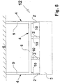
- FIG. 5 also shows an air conditioning system suspension 12 that is similar to FIG. 1 and which - Below the frame base frame 6 or above that (previously referred to as "not ... attached") Bar ends of the suspension bars 2 lying on top - one of transverse and longitudinal brackets 10, 11 integrated additional bracket is attached.
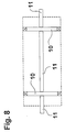
- the structure of this additional bracket and the arrangement the crosswise and mechanically connected cross and longitudinal brackets 10, 11 is in plan view 6 shown in more detail. 5
- the frame base frame 6 is not on the attached rod ends of the suspension rods 2, the latter lying on top of the Cross and longitudinal brackets 10, 11 are fixed to the frame base frame 6.
- FIG. 7 a further modification of the air conditioning system suspension 12 becomes remove. It differs from the previous versions in such a way that the one shown in FIG shown as a top view (and modified in comparison of Fig. 6) additional bracket, which also consists of cross members and side members 10, 11 (of the type described above) on the aforementioned frame base frame 6 is attached. The latter is directly at the defined force application and Transfer points of the suspension rods 4 attached, their (not on the air conditioning components attached) free rod ends of the underside of the frame base frame 6 attached rest. In addition, the frame differential carrier 9 at the defined force introduction and Transfer positions of this additional bracket fixed vertically.
- the above-described suspension of the air conditioning system 3 can be found on the aircraft structure 5 (horizontal ceiling or lower floor structure) - as usual - again.
Landscapes
- Health & Medical Sciences (AREA)
- General Health & Medical Sciences (AREA)
- Pulmonology (AREA)
- Engineering & Computer Science (AREA)
- Aviation & Aerospace Engineering (AREA)
- Body Structure For Vehicles (AREA)
- Vibration Prevention Devices (AREA)
- Vehicle Body Suspensions (AREA)
- Duct Arrangements (AREA)
- Fluid-Damping Devices (AREA)
Abstract
Description
- Fig. 1
- die Seitenansicht der (an einer horizontalen Flugzeug-Deckenstruktur) befestigten Klimaanlagenaufhängung mit der an ihr befestigten Klimaanlage;
- Fig. 2
- die Draufsicht des (der Klimaanlagenaufhängung integrierten) Aufhängerahmens;
- Fig. 3
- die Seitenansicht der (an einer abgeschrägten Flugzeug-Deckenstruktur) befestigten Klimaanlagenaufhängung mit der an ihr befestigten Klimaanlage;
- Fig. 4
- die Ansicht für eine Klimaanlagenaufhängung nach Fig. 1 mit einem modifizierten Aufhängerahmen;
- Fig. 5
- die Ansicht für eine mit der Anordnung nach Fig. 6 modifizierte Klimaanlagenaufhängung nach Fig. 1;
- Fig. 6
- die Draufsicht einer Anordnung von miteinander verbundenen Quer- und Längs-Halterungen;
- Fig. 7
- die Ansicht für eine mit der Anordnung nach Fig. 8 modifizierte Klimaanlagenaufhängung nach Fig. 1;
- Fig. 8
- die Draufsicht einer weiteren Anordnung von miteinander verbundenen Quer- und Längs-Halterungen.
- 1
- Einbauraum (Kabinenbereich unterhalb des Fußbodens gelegen)
- 2
- Aufhängestange
- 3
- Klimaanlage
- 4
- Aufhängerahmen
- 5
- Flugzeug-Struktur
- 6
- Rahmengrundgestell
- 7
- Querträger
- 8
- Längsträger
- 9
- Rahmendifferenzträger
- 10
- Querhalterung
- 11
- Längshalterung
- 12
- Klimaanlagenaufhängung
Claims (7)
- Klimaanlagenaufhängung für ein Großraum-Verkehrsflugzeug, die man zur horizontalen Aufhängung von einer im Flugzeug-Rumpfinnenbereich installierten Klimaanlage (3), die innerhalb einem hohen Einbauraum (1) an der Flugzeug-Struktur (5), befestigt ist, einsetzt, welche mehrere Befestigungseinheiten, die aus verschiedenartigen Befestigungsmitteln integriert sind, aufweist, wobei eine erste Befestigungseinheit aus der Anordnung von mehreren Aufhängestangen (2) besteht, die an definierten Krafteinleitungs- und Übertragungspositionen von verschiedenen Klimaanlagen-Komponenten, die oberhalb der Klimaanlage (3) positioniert sind, lotrecht oder etwa lotrecht stehend befestigt sind,
dadurch gekennzeichnet, dass die nicht an den Klimaanlagen-Komponenten befestigten Stangenenden der Aufhängestangen (2) an definierten Krafteinleitungs- und Übertragungspositionen von einem Aufhängerahmen (4), der eine zweite Befestigungseinheit verkörpert, befestigt sind und der Aufhängerahmen (4) an definierten Krafteinleitungs- und Übertragungspositionen unterhalb der innerhalb des Flugzeugrumpfes gelegenen Flugzeug-Struktur (5) befestigt ist. - Klimaanlagenaufhängung nach Anspruch 1, dadurch gekennzeichnet, dass der Aufhängerahmen (4) ein aus Quer- und Längsträgern (7, 8) gebildes Rahmengrundgestell (6), die miteinander verbunden sind, und mehrere auf letzterem angeordnete Rahmendifferenzträger (9), die an den definierten Krafteinleitungs- und Übertragungspositionen oberhalb des Rahmengrundgestelles (9) lotrecht oder etwa lotrecht befestigt sind, aufweist, dabei die nicht befestigten Trägerenden der Rahmendistanzträger (9) an den definierten Krafteinleitungs- und Übertragungspositionen der Flugzeug-Struktur (5) befestigt sind.
- Klimaanlagenaufhängung nach Anspruch 2, dadurch gekennzeichnet, dass wenigstens zwei nicht befestigte Trägerenden der Rahmendistanzträger (9) unterhalb der Kabinen- oder Frachtraumdecke an der metallenen Flugzeug-Innenstruktur befestigt sind.
- Klimaanlagenaufhängung nach Anspruch 3, dadurch gekennzeichnet, dass bei einem als Einfachrahmen ausgeführtem Rahmengrundgestell (6) wenigstens zwei oder bei einem als Dreieck-rahmen ausgeführtem bei einem als Dreieck-rahmen ausgeführten Rahmengrundgestell (6) wenigstens drei oder bei einem als quadrat- oder rechteckförmigen Rahmen ausgeführtem Rahmengrundgestell (6) wenigstens vier oder bei einem als Vieleckrahmen oder der Kombination aus einem der Rahmenkonstruktion mit Mehrfachaufhängung ausgeführtem Rahmengrundgestell (6) wenigstens vier oder mehr als vier nicht befestigte Trägerenden der Rahmendistanzträger (9) unterhalb der Kabinen- oder Frachtraumdecke an der metallenen Flugzeug-Innenstruktur befestigt sind.
- Klimaanlagenaufhängung nach den Ansprüchen 1 und 2, dadurch gekennzeichnet, dass unterhalb des Rahmengrundgestelles (6) mehrere mechanisch verbundene Quer- und Längshalterungen (10, 11) befestigt sind, an denen die nicht an den Klimaanlagen-Komponenten befestigten Stangenenden der Aufhängestangen (2) befestigt sind.
- Klimaanlagenaufhängung nach den Ansprüchen 1 bis 5, dadurch gekennzeichnet, dass das Rahmengrundgestell (6) an den nicht befestigten Stangenenden der Aufhängestangen (2) befestigt ist und außerdem auf den Quer- und Längshalterungen (10, 11), die obenauf liegend dem Rahmengrundgestell (6) befestigt sind, die lotrecht oder etwa lotrecht angeordneten Rahmendifferenzträger (9) an den definierten Krafteinleitungs- und Übertragungspositionen befestigt sind.
- Klimaanlagenaufhängung nach Anspruch 1, dadurch gekennzeichnet, dass der Aufhängerahmen (4) speziell dimensioniert und statisch bestimmt ist, wobei die Anzahl der Krafteinleitungs- und Übertragungspositionen zwischen dem Aufhängerahmen (4) und der zum Flugzeugrumpf-Innenraum gerichteten Flugzeug-Struktur (5) und die Biegefestigkeit der Rahmendistanzträger (9) des Aufhängerahmen (4) sowie der Aufhängestangen (2) durch die Aufhängelast der Klimaanlage (3) und den Randbedingungen der Flugsicherheit definiert ist.
Applications Claiming Priority (2)
| Application Number | Priority Date | Filing Date | Title |
|---|---|---|---|
| DE10035301 | 2000-07-18 | ||
| DE10035301A DE10035301C2 (de) | 2000-07-18 | 2000-07-18 | Klimaanlagenaufhängung für ein Großraum-Verkehrsflugzeug |
Publications (3)
| Publication Number | Publication Date |
|---|---|
| EP1174337A2 true EP1174337A2 (de) | 2002-01-23 |
| EP1174337A3 EP1174337A3 (de) | 2003-01-22 |
| EP1174337B1 EP1174337B1 (de) | 2005-09-28 |
Family
ID=7649591
Family Applications (1)
| Application Number | Title | Priority Date | Filing Date |
|---|---|---|---|
| EP01112181A Expired - Lifetime EP1174337B1 (de) | 2000-07-18 | 2001-05-18 | Klimaanlagenaufhängung für ein Grossraum-Verkehrsflugzeug |
Country Status (4)
| Country | Link |
|---|---|
| US (1) | US6499692B2 (de) |
| EP (1) | EP1174337B1 (de) |
| AT (1) | ATE305407T1 (de) |
| DE (2) | DE10035301C2 (de) |
Families Citing this family (3)
| Publication number | Priority date | Publication date | Assignee | Title |
|---|---|---|---|---|
| DE102006039290A1 (de) * | 2006-08-22 | 2008-03-13 | Airbus Deutschland Gmbh | Rahmenelement, Flugzeugkomponentenmontagesystem sowie Verfahren zur Montage einer Komponente in einem Flugzeug |
| DE102011088061A1 (de) | 2011-12-09 | 2013-06-13 | Airbus Operations Gmbh | Haltevorrichtung für eine Komponente eines Luft- oder Raumfahrzeugs |
| CN114655447B (zh) * | 2022-04-08 | 2025-04-08 | 中国飞机强度研究所 | 一种翼吊式航空发动机悬吊结构 |
Family Cites Families (8)
| Publication number | Priority date | Publication date | Assignee | Title |
|---|---|---|---|---|
| JPS5554167Y2 (de) * | 1976-07-14 | 1980-12-15 | ||
| US4702087A (en) * | 1985-03-29 | 1987-10-27 | Mitsubishi Denki Kabushiki Kaisha | Ceiling suspended air conditioner |
| US4815396A (en) * | 1987-08-31 | 1989-03-28 | Manco Corporation Of West Bend | Suspended table |
| US4862764A (en) * | 1987-08-31 | 1989-09-05 | Manco Corporation Of West Bend | Suspended table |
| US5039902A (en) * | 1989-07-06 | 1991-08-13 | Schwarz Fred M | Overhead storage system |
| US5351926A (en) * | 1992-03-25 | 1994-10-04 | Unistrut International Corp. | Support structure beam |
| JP3312871B2 (ja) * | 1998-01-29 | 2002-08-12 | 暖冷工業株式会社 | 天吊形空気調和器 |
| US6318672B1 (en) * | 1998-10-16 | 2001-11-20 | Cessna Aircraft Company | Aircraft cabinet mounting structure |
-
2000
- 2000-07-18 DE DE10035301A patent/DE10035301C2/de not_active Expired - Fee Related
-
2001
- 2001-05-18 DE DE50107546T patent/DE50107546D1/de not_active Expired - Lifetime
- 2001-05-18 EP EP01112181A patent/EP1174337B1/de not_active Expired - Lifetime
- 2001-05-18 AT AT01112181T patent/ATE305407T1/de not_active IP Right Cessation
- 2001-07-18 US US09/908,481 patent/US6499692B2/en not_active Expired - Lifetime
Non-Patent Citations (1)
| Title |
|---|
| None |
Also Published As
| Publication number | Publication date |
|---|---|
| DE50107546D1 (de) | 2006-02-09 |
| DE10035301A1 (de) | 2002-02-07 |
| US20020008176A1 (en) | 2002-01-24 |
| DE10035301C2 (de) | 2002-11-14 |
| ATE305407T1 (de) | 2005-10-15 |
| EP1174337A3 (de) | 2003-01-22 |
| US6499692B2 (en) | 2002-12-31 |
| EP1174337B1 (de) | 2005-09-28 |
Similar Documents
| Publication | Publication Date | Title |
|---|---|---|
| DE102005054890B4 (de) | Flugzeugrumpfstruktur mit einer Passagierkabine und einer Befestigungsstruktur zur Fixierung von Inneneinrichtungskomponenten in der Passagierkabine | |
| DE60029963T2 (de) | Lasttragende Strukturen | |
| EP2435310B1 (de) | Transportvorrichtung zur verwendung bei der montage von interieurkomponentenmodulen in einem flugzeug | |
| DE102010014302B4 (de) | Luftfahrzeug und Befestigungsanordnung für eine Fußbodenstruktur in einem Luftfahrzeug | |
| DE69201032T2 (de) | Sicherungsvorrichtung für die Hinteraufhängung eines Turbinetriebwerkes. | |
| EP2435311B1 (de) | Verfahren und system zur montage von interieurkomponenten in einem flugzeug | |
| EP0983938A2 (de) | Gepäckablageanordnung in einer Flugzeugpassagierkabine | |
| EP2310259B1 (de) | Vormontage und integration von flugzeugkabinen | |
| DE602005006280T2 (de) | Modulares wandkonstruktionssystem für flugzeugkabinen | |
| DE102018123531B4 (de) | Verfahren zum Installieren von Systemkomponenten in einem Abschnitt eines Flugzeugrumpfs | |
| DE602004001565T2 (de) | Aufhängevorrichtung eines Triebwerks unter einem Flugzeugflügel | |
| EP2228296B1 (de) | Frachtraumboden für einen Frachtraum eines Flugzeugs sowie Verfahren zur Montage eines solchen | |
| DE102011102364A1 (de) | Freitragendes Kabinenstruktursegment | |
| EP3016843B1 (de) | Überflurfördereinrichtung mit traggerüstmodulen | |
| DE4030921A1 (de) | Rahmenstruktur fuer einen kraftfahrzeug-endbereich | |
| DE60202813T2 (de) | Schubbefestigung eines Triebwerkes an einem Luftfahrzeug | |
| DE69310344T2 (de) | Flugzeug mit mindestens zwei triebwerken fü jede tragfläche | |
| DE102007032481A1 (de) | Fahrzeugaufbau | |
| DE102012005353A1 (de) | Flugzeugrumpfstruktur mit Querprofilen und Fachwerkstruktur | |
| DE10035301C2 (de) | Klimaanlagenaufhängung für ein Großraum-Verkehrsflugzeug | |
| DE102005003296B4 (de) | Rumpfhecksektion eines Flugzeugs | |
| EP1550606B1 (de) | Seitenleitwerksanschluss | |
| DE102004047858B3 (de) | Hilfsrahmen für einen Fahrgestellrahmen eines Nutzfahrzeugs | |
| EP3816047A1 (de) | Modulares flugkörperstartsystem zum starten von flugkörpern von einer mobilen plattform aus | |
| EP2436599A2 (de) | Halterung für Inneneinrichtungskomponenten in Flugzeugkabinen |
Legal Events
| Date | Code | Title | Description |
|---|---|---|---|
| PUAI | Public reference made under article 153(3) epc to a published international application that has entered the european phase |
Free format text: ORIGINAL CODE: 0009012 |
|
| AK | Designated contracting states |
Kind code of ref document: A2 Designated state(s): AT BE CH CY DE DK ES FI FR GB GR IE IT LI LU MC NL PT SE TR |
|
| AX | Request for extension of the european patent |
Free format text: AL;LT;LV;MK;RO;SI |
|
| RAP1 | Party data changed (applicant data changed or rights of an application transferred) |
Owner name: AIRBUS DEUTSCHLAND GMBH |
|
| PUAL | Search report despatched |
Free format text: ORIGINAL CODE: 0009013 |
|
| AK | Designated contracting states |
Kind code of ref document: A3 Designated state(s): AT BE CH CY DE DK ES FI FR GB GR IE IT LI LU MC NL PT SE TR |
|
| AX | Request for extension of the european patent |
Free format text: AL;LT;LV;MK;RO;SI |
|
| 17P | Request for examination filed |
Effective date: 20030111 |
|
| AKX | Designation fees paid |
Designated state(s): AT BE CH CY DE DK ES FI FR GB GR IE IT LI LU MC NL PT SE TR |
|
| 17Q | First examination report despatched |
Effective date: 20030904 |
|
| GRAP | Despatch of communication of intention to grant a patent |
Free format text: ORIGINAL CODE: EPIDOSNIGR1 |
|
| GRAS | Grant fee paid |
Free format text: ORIGINAL CODE: EPIDOSNIGR3 |
|
| GRAA | (expected) grant |
Free format text: ORIGINAL CODE: 0009210 |
|
| AK | Designated contracting states |
Kind code of ref document: B1 Designated state(s): AT BE CH CY DE DK ES FI FR GB GR IE IT LI LU MC NL PT SE TR |
|
| PG25 | Lapsed in a contracting state [announced via postgrant information from national office to epo] |
Ref country code: IT Free format text: LAPSE BECAUSE OF FAILURE TO SUBMIT A TRANSLATION OF THE DESCRIPTION OR TO PAY THE FEE WITHIN THE PRESCRIBED TIME-LIMIT;WARNING: LAPSES OF ITALIAN PATENTS WITH EFFECTIVE DATE BEFORE 2007 MAY HAVE OCCURRED AT ANY TIME BEFORE 2007. THE CORRECT EFFECTIVE DATE MAY BE DIFFERENT FROM THE ONE RECORDED. Effective date: 20050928 Ref country code: FI Free format text: LAPSE BECAUSE OF FAILURE TO SUBMIT A TRANSLATION OF THE DESCRIPTION OR TO PAY THE FEE WITHIN THE PRESCRIBED TIME-LIMIT Effective date: 20050928 Ref country code: NL Free format text: LAPSE BECAUSE OF FAILURE TO SUBMIT A TRANSLATION OF THE DESCRIPTION OR TO PAY THE FEE WITHIN THE PRESCRIBED TIME-LIMIT Effective date: 20050928 Ref country code: IE Free format text: LAPSE BECAUSE OF FAILURE TO SUBMIT A TRANSLATION OF THE DESCRIPTION OR TO PAY THE FEE WITHIN THE PRESCRIBED TIME-LIMIT Effective date: 20050928 |
|
| REG | Reference to a national code |
Ref country code: GB Ref legal event code: FG4D Free format text: NOT ENGLISH |
|
| REG | Reference to a national code |
Ref country code: CH Ref legal event code: EP |
|
| REG | Reference to a national code |
Ref country code: IE Ref legal event code: FG4D Free format text: LANGUAGE OF EP DOCUMENT: GERMAN |
|
| PG25 | Lapsed in a contracting state [announced via postgrant information from national office to epo] |
Ref country code: GR Free format text: LAPSE BECAUSE OF FAILURE TO SUBMIT A TRANSLATION OF THE DESCRIPTION OR TO PAY THE FEE WITHIN THE PRESCRIBED TIME-LIMIT Effective date: 20051228 Ref country code: DK Free format text: LAPSE BECAUSE OF FAILURE TO SUBMIT A TRANSLATION OF THE DESCRIPTION OR TO PAY THE FEE WITHIN THE PRESCRIBED TIME-LIMIT Effective date: 20051228 Ref country code: SE Free format text: LAPSE BECAUSE OF FAILURE TO SUBMIT A TRANSLATION OF THE DESCRIPTION OR TO PAY THE FEE WITHIN THE PRESCRIBED TIME-LIMIT Effective date: 20051228 |
|
| PG25 | Lapsed in a contracting state [announced via postgrant information from national office to epo] |
Ref country code: ES Free format text: LAPSE BECAUSE OF FAILURE TO SUBMIT A TRANSLATION OF THE DESCRIPTION OR TO PAY THE FEE WITHIN THE PRESCRIBED TIME-LIMIT Effective date: 20060108 |
|
| GBT | Gb: translation of ep patent filed (gb section 77(6)(a)/1977) |
Effective date: 20060107 |
|
| REF | Corresponds to: |
Ref document number: 50107546 Country of ref document: DE Date of ref document: 20060209 Kind code of ref document: P |
|
| PG25 | Lapsed in a contracting state [announced via postgrant information from national office to epo] |
Ref country code: PT Free format text: LAPSE BECAUSE OF FAILURE TO SUBMIT A TRANSLATION OF THE DESCRIPTION OR TO PAY THE FEE WITHIN THE PRESCRIBED TIME-LIMIT Effective date: 20060228 |
|
| NLV1 | Nl: lapsed or annulled due to failure to fulfill the requirements of art. 29p and 29m of the patents act | ||
| REG | Reference to a national code |
Ref country code: IE Ref legal event code: FD4D |
|
| PG25 | Lapsed in a contracting state [announced via postgrant information from national office to epo] |
Ref country code: AT Free format text: LAPSE BECAUSE OF NON-PAYMENT OF DUE FEES Effective date: 20060518 |
|
| PG25 | Lapsed in a contracting state [announced via postgrant information from national office to epo] |
Ref country code: MC Free format text: LAPSE BECAUSE OF NON-PAYMENT OF DUE FEES Effective date: 20060531 Ref country code: LI Free format text: LAPSE BECAUSE OF NON-PAYMENT OF DUE FEES Effective date: 20060531 Ref country code: CH Free format text: LAPSE BECAUSE OF NON-PAYMENT OF DUE FEES Effective date: 20060531 Ref country code: BE Free format text: LAPSE BECAUSE OF NON-PAYMENT OF DUE FEES Effective date: 20060531 |
|
| ET | Fr: translation filed | ||
| PLBE | No opposition filed within time limit |
Free format text: ORIGINAL CODE: 0009261 |
|
| STAA | Information on the status of an ep patent application or granted ep patent |
Free format text: STATUS: NO OPPOSITION FILED WITHIN TIME LIMIT |
|
| 26N | No opposition filed |
Effective date: 20060629 |
|
| REG | Reference to a national code |
Ref country code: CH Ref legal event code: PL |
|
| BERE | Be: lapsed |
Owner name: AIRBUS DEUTSCHLAND G.M.B.H. Effective date: 20060531 |
|
| PG25 | Lapsed in a contracting state [announced via postgrant information from national office to epo] |
Ref country code: TR Free format text: LAPSE BECAUSE OF FAILURE TO SUBMIT A TRANSLATION OF THE DESCRIPTION OR TO PAY THE FEE WITHIN THE PRESCRIBED TIME-LIMIT Effective date: 20050928 Ref country code: LU Free format text: LAPSE BECAUSE OF NON-PAYMENT OF DUE FEES Effective date: 20060518 |
|
| PG25 | Lapsed in a contracting state [announced via postgrant information from national office to epo] |
Ref country code: CY Free format text: LAPSE BECAUSE OF FAILURE TO SUBMIT A TRANSLATION OF THE DESCRIPTION OR TO PAY THE FEE WITHIN THE PRESCRIBED TIME-LIMIT Effective date: 20050928 |
|
| REG | Reference to a national code |
Ref country code: FR Ref legal event code: CD Owner name: AIRBUS OPERATIONS GMBH Effective date: 20111118 |
|
| REG | Reference to a national code |
Ref country code: FR Ref legal event code: PLFP Year of fee payment: 16 |
|
| PGFP | Annual fee paid to national office [announced via postgrant information from national office to epo] |
Ref country code: DE Payment date: 20160520 Year of fee payment: 16 Ref country code: GB Payment date: 20160520 Year of fee payment: 16 |
|
| PGFP | Annual fee paid to national office [announced via postgrant information from national office to epo] |
Ref country code: FR Payment date: 20160520 Year of fee payment: 16 |
|
| REG | Reference to a national code |
Ref country code: DE Ref legal event code: R119 Ref document number: 50107546 Country of ref document: DE |
|
| GBPC | Gb: european patent ceased through non-payment of renewal fee |
Effective date: 20170518 |
|
| REG | Reference to a national code |
Ref country code: FR Ref legal event code: ST Effective date: 20180131 |
|
| PG25 | Lapsed in a contracting state [announced via postgrant information from national office to epo] |
Ref country code: GB Free format text: LAPSE BECAUSE OF NON-PAYMENT OF DUE FEES Effective date: 20170518 Ref country code: DE Free format text: LAPSE BECAUSE OF NON-PAYMENT OF DUE FEES Effective date: 20171201 |
|
| PG25 | Lapsed in a contracting state [announced via postgrant information from national office to epo] |
Ref country code: FR Free format text: LAPSE BECAUSE OF NON-PAYMENT OF DUE FEES Effective date: 20170531 |