EP1174201A1 - Dispositif pour râper le canal intra-médullaire d'un os et procédé de fabrication du dispositif - Google Patents
Dispositif pour râper le canal intra-médullaire d'un os et procédé de fabrication du dispositif Download PDFInfo
- Publication number
- EP1174201A1 EP1174201A1 EP01401883A EP01401883A EP1174201A1 EP 1174201 A1 EP1174201 A1 EP 1174201A1 EP 01401883 A EP01401883 A EP 01401883A EP 01401883 A EP01401883 A EP 01401883A EP 1174201 A1 EP1174201 A1 EP 1174201A1
- Authority
- EP
- European Patent Office
- Prior art keywords
- shape
- teeth
- machining
- toothing
- obtaining
- Prior art date
- Legal status (The legal status is an assumption and is not a legal conclusion. Google has not performed a legal analysis and makes no representation as to the accuracy of the status listed.)
- Granted
Links
- 210000000988 bone and bone Anatomy 0.000 title claims description 20
- 238000004519 manufacturing process Methods 0.000 title description 3
- 238000003754 machining Methods 0.000 claims abstract description 47
- 238000000034 method Methods 0.000 claims abstract description 25
- 239000011295 pitch Substances 0.000 claims description 19
- 229910003460 diamond Inorganic materials 0.000 claims description 6
- 239000010432 diamond Substances 0.000 claims description 6
- 238000003780 insertion Methods 0.000 claims description 4
- 230000037431 insertion Effects 0.000 claims description 4
- 238000003466 welding Methods 0.000 claims description 3
- 238000012360 testing method Methods 0.000 claims description 2
- 239000007943 implant Substances 0.000 description 4
- 238000005520 cutting process Methods 0.000 description 3
- 230000003247 decreasing effect Effects 0.000 description 2
- 238000011161 development Methods 0.000 description 2
- 230000018109 developmental process Effects 0.000 description 2
- 238000009826 distribution Methods 0.000 description 2
- 230000000694 effects Effects 0.000 description 2
- 238000000227 grinding Methods 0.000 description 2
- 230000001788 irregular Effects 0.000 description 2
- 238000005304 joining Methods 0.000 description 2
- 230000036244 malformation Effects 0.000 description 2
- 238000003801 milling Methods 0.000 description 2
- 230000035515 penetration Effects 0.000 description 2
- 238000002360 preparation method Methods 0.000 description 2
- 208000031968 Cadaver Diseases 0.000 description 1
- 208000005189 Embolism Diseases 0.000 description 1
- 238000013459 approach Methods 0.000 description 1
- 206010003246 arthritis Diseases 0.000 description 1
- 238000011882 arthroplasty Methods 0.000 description 1
- 230000015572 biosynthetic process Effects 0.000 description 1
- 230000037237 body shape Effects 0.000 description 1
- 210000001185 bone marrow Anatomy 0.000 description 1
- 239000004568 cement Substances 0.000 description 1
- 239000011248 coating agent Substances 0.000 description 1
- 238000000576 coating method Methods 0.000 description 1
- 230000001054 cortical effect Effects 0.000 description 1
- 208000014674 injury Diseases 0.000 description 1
- 238000012986 modification Methods 0.000 description 1
- 230000004048 modification Effects 0.000 description 1
- 201000008482 osteoarthritis Diseases 0.000 description 1
- 230000007170 pathology Effects 0.000 description 1
- BASFCYQUMIYNBI-UHFFFAOYSA-N platinum Chemical compound [Pt] BASFCYQUMIYNBI-UHFFFAOYSA-N 0.000 description 1
- OANVFVBYPNXRLD-UHFFFAOYSA-M propyromazine bromide Chemical compound [Br-].C12=CC=CC=C2SC2=CC=CC=C2N1C(=O)C(C)[N+]1(C)CCCC1 OANVFVBYPNXRLD-UHFFFAOYSA-M 0.000 description 1
- 239000000700 radioactive tracer Substances 0.000 description 1
- 230000000284 resting effect Effects 0.000 description 1
- 229910001220 stainless steel Inorganic materials 0.000 description 1
- 239000010935 stainless steel Substances 0.000 description 1
- 230000008733 trauma Effects 0.000 description 1
- 238000009827 uniform distribution Methods 0.000 description 1
Images

Classifications
-
- A—HUMAN NECESSITIES
- A61—MEDICAL OR VETERINARY SCIENCE; HYGIENE
- A61B—DIAGNOSIS; SURGERY; IDENTIFICATION
- A61B17/00—Surgical instruments, devices or methods
- A61B17/16—Instruments for performing osteoclasis; Drills or chisels for bones; Trepans
- A61B17/1659—Surgical rasps, files, planes, or scrapers
-
- B—PERFORMING OPERATIONS; TRANSPORTING
- B23—MACHINE TOOLS; METAL-WORKING NOT OTHERWISE PROVIDED FOR
- B23C—MILLING
- B23C3/00—Milling particular work; Special milling operations; Machines therefor
-
- B—PERFORMING OPERATIONS; TRANSPORTING
- B23—MACHINE TOOLS; METAL-WORKING NOT OTHERWISE PROVIDED FOR
- B23C—MILLING
- B23C3/00—Milling particular work; Special milling operations; Machines therefor
- B23C3/16—Working surfaces curved in two directions
- B23C3/18—Working surfaces curved in two directions for shaping screw-propellers, turbine blades, or impellers
Definitions
- the present invention relates to a device for grating the intramedullary canal of a bone.
- the invention also relates to a manufacturing method of the device.
- the bone marrow preparation or bone calibration is carried out using a grated. This precisely shapes the intramedullary canal so that the volume obtained is in correspondence with the volume of the implant to be square.
- the grater is covered on its outer envelope partially or completely a set of teeth which will cut and pack the cancellous bone and cortical.
- teeth parameters cutting angle, flat at the top of the tooth, pitch, orientation of teeth.
- pyramidal teeth it is possible to vary the angle of inclination of the faces of the pyramid.
- the tip of the pyramid can therefore be oriented in opposition to the cut.
- the object of the present invention is therefore to overcome the drawbacks of the prior art by proposing a continuous machining process adapted to a shape any, allowing to master the different types of teeth and the geometric characteristics of the teeth.
- Another object of the invention is to provide a grater, the manufacture of which requires the implementation of the method described above, in which the mechanical stresses in service are distributed over the entire surface of the grater and on which it is possible to obtain a homogeneous distribution of the teeth.
- a rasp (1) is intended to prepare the intramedullary canal a bone into which a prosthesis is inserted.
- the grater (1) presented is suitable for calibrating the femoral canal.
- Each grater (1) has a shape variable according to the shape of the intramedullary canal of the bone that the user wish to prepare.
- the rasp consists of a body (2) comprising an upper face (20) and an outer casing (21) loaded to grate the inner wall of the canal.
- the body (2) ends in a shape profile (22) intended to facilitate the insertion of the rasp (1) into the channel.
- the geometric elements such as pins (201), grooves or bores, male or female, arranged on the upper face (20) of the body (2) constitute a latching system intended to receive a constituting end-piece the end of a handle for manipulating the grater in the channel and intended for possibly receive trial prosthetic components.
- the face upper (20) of the body (2) may be flat or may include a stud allowing the welding of a handle to manipulate the grater (1) in the bone.
- the body (2) of the grater (1) has an elongated shape along an axis (3) substantially parallel to the longitudinal axis of the channel.
- the cross section of the body (2) of the grater (1) is variable along the body (2), then decreasing on its final end, ending with the profile shape (22) intended to facilitate the insertion of the rasp (1).
- the shape of the cross section of the lower part of the grater (1) is substantially constant.
- the shape of the cross section of the body (2) is gradually variable and greater than the cross section of the lower part of the body (2).
- the junction between the lower part and the upper part is made by a continuity of the curves forming the surfaces.
- the upper face (20) of the body (2) is inclined relative to the axis (3) of the rasp (1).
- machining along a curve geometric in the form of a helix (210) is made on the wall outside (21) of the body (2) of the grater (1).
- the helical curve (210) is first drawn on the outer casing (21) of the body (2) of the grater (1) using software computer science.
- This software allows to build propellers with constant pitch or variable on any form coming from a file.
- the software uses the following method to build a propeller on any shape, such than that of the grater (1) of the invention.
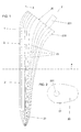
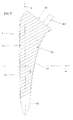
- the body shape (2) of the grater is defined by generators (23) resting on the envelope surface (21) as shown in Figures 1 and 3.
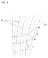
- a generator (230) of the body (2) of the grater (1) several points are positioned, distant between each of them constant, defined by p, of the helical curve that we want to plot.
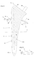
- Figure 4 is a simplified representation of the rasp on which is draw a helical curve of constant pitch.
- the pitch of the curve in helix that we wish to represent being constant and the cross section of the body (2) of the grater (1) being variable
- the angle of the helical curve defined by relation to the axis (4) perpendicular to the axis (3) of the grater (1), is in reality not constant as shown in this figure.
- Cross section in the upper part of the body (2) of the grater (1) being greater than that of the lower part of the body (2) of the rasp (1), the angle of the helical curve varies by decreasing from the bottom to the top of the body (2) of the grater (1).
- the representations are also simplified in FIGS. 7, 8 and 9.
- the angle of the helical curve is variable along the body (2) of the grater (1), but we will speak all the same propeller tilt corresponding to the maximum angle of the helical curve. This angle is maximum where the cross section of the body (2) of the rasp (1) is the smallest, i.e. on the lower part of the body (2) of the grater (1).
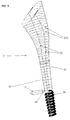
- machining can begin along the route of the helical curve, as shown in figure 6.
- Machining is carried out with a tool (5) shown in Figure 5, milling cutter or grinding wheel, having a head (50) beveled.
- This head (50) can have different widths I and a bevel whose angle, defined by ⁇ and ⁇ 'equal or different, can vary depending the efficiency that one wishes to give to the grater (1). Machining depth varies depending on the value of the width I and the angle of the beveled head.
- the milling cutter or grinding wheel is rotated along an axis (51) maintained in permanence parallel to the tangents to the points belonging to the generators (23) successive and forming the helical curve (210), as shown Figures 4 and 6.
- the software traces the normal to the surface of the outer envelope (21) of the body (2).
- the tool (5) machines the outer casing (21) of the body (2) of the grater (1) along the propeller (210) traced, the head (50) of the tool (5) being oriented so so that it follows the orientation of the traced normals. This machining is carried out on a machine with at least five axes.
- the body (2) of the rasp (1) has a net (24), as shown in FIGS. 6 and 7.
- This net profile (24) limits the risk of breakage, because the work efforts are no longer concentrated only on the weakest section but they are distributed over the full height of the teeth.
- continuous helical machining allows avoid calibration overpressures in the near environment physiological thus limiting the risk of fatty embolism when using the rasp, because the bone chip clearance area is no longer closed.
- the rasp In the case where the machining is carried out according to a propeller (210) with a slight inclination, the rasp then has a toothing of the straight toothing type.
- the width of the bevel head (50) of the tool (5), defined by I, could, for example, be substantially equal to or greater than the pitch p of the propeller (210), so as to form a cutting net (24) and therefore more effective.
- the pitch of the propeller (210) could, for example, be variable along the body (2) of the grater (1).
- the machining is carried out according to two helical curves (211, 212) on the outer envelope (21) of the body (2) of the grater (1).
- Two helical curves (211, 212) are first drawn according to the method presented above, as shown in Figure 8. These propellers (211, 212) have the particularity of being inverted steps. They will preferably be different inclinations with respect to the axis (4).
- the two propellers (211, 212) can have constant steps, respectively p 'and p ", equal or different.
- the spaces (213) thus formed by the intersections of the two helices (211, 212) are regular and evenly distributed over the entire surface of the body (2) of the grater (1).
- the two machining operations are carried out according to the method presented above.
- the head (50) of the tool (5) is chosen so that its width I is substantially equal to or greater than the pitch (p ', p ") of the propeller (211, 212) which it follows, to form, after machining, a cutting thread. Machining with this tool (5) following the two propellers (211, 212) of inverted steps will therefore form teeth (214), as shown in Figure 8.
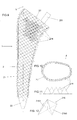
- teeth (214), by the bevel shape of the head (50) of the tool (5), with ⁇ and ⁇ 'equal and in the case of a depth of constant and equal penetration of the tool (5) along the two propellers (211, 212), of equal p 'and p ", are points in the form of regular pyramids (215), as shown in Figures 11 and 12.
- These pyramids (215) are based (2150) the spaces (213) formed by the intersections of the two propellers (211, 212) of not inverted and their height is normal to the surface of the body (2) of the grater (1).
- These teeth (214) in the form of regular pyramids (215) are points of diamond and are very aggressive.
- the angle of the beveled head (50) can vary from one machining to another and by varying the value of the angles ⁇ and ⁇ 'of the bevel head, i.e. with ⁇ different from ⁇ ', it is possible to obtain irregular pyramids whose top is offset.
- each propeller (211, 212) are not constant and vary along the body (2) of the grater (1).
- the section (213) constituting the base of the teeth (214) will be variable as a function of the evolution of the steps p 'and p ".
- the two machining depths according to respectively the two propellers (211, 212) are different, so as to create teeth with chipbreaker.
- This machining according to two inverted pitch propellers therefore allows obtain a uniform distribution of the teeth (214) over the entire envelope outside (21) of the body (2) of the grater (1) and in particular at the places of more rounded junction of the envelope (21). So the calibration of the inner wall of the intramedullary canal will be complete and homogeneous, the entire surface in correspondence with the implant will have been worked.
- the height of the teeth is shown irregularly because the the highest teeth (214) are those in the foreground and the lowest ones from the background. It should be understood that, compared to a rasp contour (1) corresponding to a section following the inclination of a propeller (211, 212) as shown in Figure 9, the height of the teeth (214) is constant over this contour in the case where the two steps p 'and p "are constant and the penetration of the tool (5) also.
- the grater can be made of stainless steel X5 Cr Ni Cu Nb 16.04 heat treated. It can have a length L of 150 mm, a section D of 12 mm, a pitch p 'of 3 mm, a pitch p "of 3 mm also, angles ⁇ 'and ⁇ "of 30 ° and 50 ° respectively and a radius of 0.5 mm tooth base.
- the machining is carried out with a tool (5) having a beveled head (50).
- the machining is carried out using a propeller (210) of slight inclination, so as to obtain a teeth of typical appearance straight teeth.
- the machining is carried out at depths different respectively according to several propellers of different inclinations, so as to obtain a toothing with chipbreaker.
- the machining is carried out using two propellers (211, 212) of inverted steps, so as to obtain teeth (214), the teeth (214) having for base (213) the spaces formed by the intersections of the two propellers (211, 212).
- the machining is carried out according to the two propellers (211, 212) at the same depth, so as to obtain a toothing diamond point type, the orientation of the teeth being normal to the envelope.
- the pitches of the two propellers (211, 212) are constant and equal, so as to obtain teeth (214) having the shape of regular pyramids (215).
- the two propellers (212, 213) have different inclinations so that the teeth (214) formed by the tool passage (5) are not aligned.
- each propeller (210, 211, 212) is constant along the envelope of any shape.
- the teeth (214) can be flat or radiated on their upper part, including in the profile of the head (50) beveled tool (5) a flat or radiated part.
- the grater (1) obtained using the process presented above and intended to prepare the intramedullary canal of a bone so that this one receives a prosthesis, is characterized in that it comprises a body (2), elongated along an axis (3) substantially parallel to the longitudinal axis of the channel, in section variable transverse, consisting of a so-called upper face (20) and a outer casing (21), and has a shape capable of collaborating with the inner wall of the intramedullary canal of the bone.
- the body (2) of the grater (1) ends in a profiled shape (22) to facilitate the insertion of the rasp (1) into the channel.
- male geometric elements or females arranged on the upper face (20) of the body (2) constitute a latching system intended to receive a tip constituting the end a handle for manipulating the grater (1) in the channel and intended to receive possibly prosthetic test components.
- the upper face (20) of the body (2) is flat or has a tenon allowing the welding of a handle to handle the grater (1) in the bone.
Landscapes
- Health & Medical Sciences (AREA)
- Engineering & Computer Science (AREA)
- Surgery (AREA)
- Mechanical Engineering (AREA)
- Life Sciences & Earth Sciences (AREA)
- Molecular Biology (AREA)
- General Health & Medical Sciences (AREA)
- Orthopedic Medicine & Surgery (AREA)
- Oral & Maxillofacial Surgery (AREA)
- Biomedical Technology (AREA)
- Heart & Thoracic Surgery (AREA)
- Medical Informatics (AREA)
- Dentistry (AREA)
- Animal Behavior & Ethology (AREA)
- Nuclear Medicine, Radiotherapy & Molecular Imaging (AREA)
- Public Health (AREA)
- Veterinary Medicine (AREA)
- Surgical Instruments (AREA)
- Steering Controls (AREA)
- Coating By Spraying Or Casting (AREA)
- Ultra Sonic Daignosis Equipment (AREA)
- Numerical Control (AREA)
- Prostheses (AREA)
- Medicines Containing Plant Substances (AREA)
Abstract
Description
- selon la pathologie à traiter (traumatisme, arthrose, malformation,...),
- selon l'état de santé du patient,
- selon le type de voie d'abord et de technique opératoire (voie antérieure, voie postérieure, avec ou sans trochantérotomie...),
- du type de géométrie de la prothèse (forme autobloquante ou non, anatomique ou droite, avec ou sans platine d'appui, section ovoïde ou rectangulaire,...),
- du type de fixation (avec ou sans ciment, avec ou sans revêtement,...)
- la denture droite,
- la denture droite avec brise-copeaux,
- la denture pointe diamant en forme de pyramide.
- la figure 1 représente, en vue de côté, la râpe selon l'invention sur laquelle sont tracées quelques génératrices,
- la figure 2 représente, en vue suivant F, la face supérieure de la râpe,
- la figure 3 représente une portion de la râpe en perspective sur laquelle est tracée une portion de courbe en hélice,
- la figure 4 représente, en vue de côté et simplifiée, la râpe avant usinage, sur laquelle a été tracée une courbe en forme d'hélice,
- la figure 5 représente, en vue de côté, l'outil utilisé pour l'usinage,
- la figure 6 représente, en perspective, le corps d'une râpe usiné partiellement suivant une hélice de pas constant,
- la figure 7 représente, en vue de côté et simplifiée, la râpe à la suite d'un usinage,
- la figure 8 représente, en vue de côté et simplifiée, la râpe sur laquelle a été tracée deux courbes en hélice,
- la figure 9 représente, en vue de côté et simplifiée, la râpe après un usinage suivant deux courbes en hélice,
- la figure 10 représente une section de la râpe suivant l'inclinaison d'une courbe en hélice après un usinage suivant deux courbes en hélice,
- la figure 11 représente, en vue de côté, les dents obtenues après l'usinage suivant les deux hélices,
- la figure 12 représente, en perspective, une dent en forme de pyramide régulière.
- tracer la normale à la surface en une pluralité de points pris le long de l'hélice (210),
- faire suivre l'hélice à la tête (50) de l'outil (5), en orientant la tête (5) de manière à ce qu'elle suive l'orientation des normales déterminées.
Claims (14)
- Procédé d'usinage pour obtenir une denture sur la surface d'une forme quelconque par un outil (5) muni d'une tête (50), suivant au moins une courbe géométrique tracée sur l'enveloppe de la forme quelconque et ayant la forme d'une hélice (210), caractérisé en ce qu'il comprend les étapes suivantes :tracer la normale à la surface en une pluralité de points pris le long de l'hélice (210),faire suivre l'hélice à la tête (50) de l'outil (5), en orientant la tête (5) de manière à ce qu'elle suive l'orientation des normales déterminées.
- Procédé d'usinage pour obtenir une denture sur la surface d'une forme quelconque selon la revendication 1, caractérisée en ce que l'usinage est réalisé avec un outil (5) disposant d'une tête (50) de forme biseautée.
- Procédé d'usinage pour obtenir une denture sur la surface d'une forme quelconque selon la revendication 2, caractérisé en ce que l'usinage est réalisé suivant une hélice (210) de faible inclinaison, de manière à obtenir une denture d'aspect type denture droite.
- Procédé d'usinage pour obtenir une denture sur la surface d'une forme quelconque selon la revendication 2, caractérisée en ce que l'usinage est réalisé à des profondeurs différentes respectivement suivant plusieurs hélices d'inclinaisons différentes, de manière à obtenir une denture avec brise-copeaux.
- Procédé d'usinage pour obtenir une denture sur la surface d'une forme quelconque selon la revendication 2, caractérisée en ce que l'usinage est réalisé suivant deux hélices (211, 212) de pas inversés, de manière à obtenir des dents (214), les dents (214) ayant pour base (213) les espaces formés par les intersections des deux hélices (211, 212).
- Procédé d'usinage pour obtenir une denture sur la surface d'une forme quelconque selon la revendication 5, caractérisé en ce que l'usinage est réalisé suivant les deux hélices (211, 212) à la même profondeur, de manière à obtenir une denture type pointe de diamant, l'orientation des dents étant normale à l'enveloppe.
- Procédé d'usinage pour obtenir une denture sur la surface d'une forme quelconque selon la revendication 6, caractérisé en ce que les pas des deux hélices (211, 212) sont constants et égaux, de manière à obtenir des dents (214) ayant la forme de pyramides régulières (215).
- Procédé d'usinage pour obtenir une denture sur la surface d'une forme quelconque selon l'une quelconque des revendications 5 à 7, caractérisé en ce que les deux hélices (212, 213) ont des inclinaisons différentes de manière à ce que les dents (214) formées par le passage de l'outil (5) ne soient pas alignées.
- Procédé d'usinage pour obtenir une denture sur la surface d'une forme quelconque selon l'une quelconque des revendications 1 à 6 et 8, caractérisé en ce que le pas de chaque hélice (210, 211, 212) est constant le long de l'enveloppe de la forme quelconque.
- Procédé d'usinage pour obtenir une denture sur la surface d'une forme quelconque selon la revendication 5, caractérisé en ce que les dents (214) peuvent être plates ou rayonnées sur leur partie supérieure, en incluant dans le profil de la tête (50) biseautée de l'outil (5) une partie plane ou rayonnée.
- Utilisation du procédé selon les revendications 1 à 10 pour former une râpe (1) destinée à préparer le canal intra-médullaire d'un os pour que celui-ci reçoive une prothèse, caractérisé en ce que la râpe (1) comprend un corps (2), allongé selon un axe (3) sensiblement parallèle à l'axe longitudinal du canal, à section transversale variable, constitué d'une face dite supérieure (20) et d'une enveloppe extérieure (21), et a une forme apte à collaborer avec la paroi interne du canal intra-médullaire de l'os.
- Utilisation du procédé selon la revendication 11, caractérisée en ce que le corps (2) de la râpe (1) se termine par une forme profilée (22) pour faciliter l'enfoncement de la râpe (1) dans le canal.
- Utilisation du procédé selon la revendication 11 ou 12, caractérisé en ce que des éléments géométriques mâles ou femelles, disposés sur la face supérieure (20) du corps (2) constituent un système d'encliquetage destiné à recevoir un embout constituant l'extrémité d'un manche pour manipuler la râpe (1) dans le canal et destiné à recevoir éventuellement des composants prothétiques d'essais.
- Utilisation du procédé selon l'une quelconque des revendications 11 à 13, caractérisé en ce que la face supérieure (20) du corps (2) est plane ou comporte un tenon permettant la soudure d'un manche pour manipuler la râpe (1) dans l'os.
Applications Claiming Priority (2)
| Application Number | Priority Date | Filing Date | Title |
|---|---|---|---|
| FR0009527A FR2811923B1 (fr) | 2000-07-20 | 2000-07-20 | Dispositif pour raper le canal intra-medullaire d'un os et procede de fabrication du dispositif |
| FR0009527 | 2000-07-20 |
Publications (2)
| Publication Number | Publication Date |
|---|---|
| EP1174201A1 true EP1174201A1 (fr) | 2002-01-23 |
| EP1174201B1 EP1174201B1 (fr) | 2006-01-25 |
Family
ID=8852736
Family Applications (1)
| Application Number | Title | Priority Date | Filing Date |
|---|---|---|---|
| EP01401883A Expired - Lifetime EP1174201B1 (fr) | 2000-07-20 | 2001-07-13 | Procédé de fabrication d'une denture sur une surface |
Country Status (6)
| Country | Link |
|---|---|
| US (1) | US6585741B2 (fr) |
| EP (1) | EP1174201B1 (fr) |
| AT (1) | ATE316435T1 (fr) |
| DE (1) | DE60116846T2 (fr) |
| ES (1) | ES2258516T3 (fr) |
| FR (1) | FR2811923B1 (fr) |
Cited By (2)
| Publication number | Priority date | Publication date | Assignee | Title |
|---|---|---|---|---|
| FR2859619A1 (fr) | 2003-09-16 | 2005-03-18 | Jean Christophe Grimard | Dispositif pour raper le canal intra-medullaire d'un os et systeme pour mettre en oeuvre ce dispositif |
| EP1698304A1 (fr) | 2005-03-01 | 2006-09-06 | A.T.S. Sferic S.A.S. | Prothèse à aspérités auto-impactable |
Families Citing this family (5)
| Publication number | Priority date | Publication date | Assignee | Title |
|---|---|---|---|---|
| US6932821B2 (en) * | 2002-09-28 | 2005-08-23 | Precimed S.A. | Femoral broach with undercut teeth |
| US20050080422A1 (en) * | 2003-10-14 | 2005-04-14 | Centerpulse Spine-Tech, Inc. | Instruments for use with implants, and methods |
| FR2930887A1 (fr) | 2008-05-06 | 2009-11-13 | Ats Sferic Stellite S A S Soc | Instrument chirurgical invasif muni d'un transpondeur |
| US12369923B2 (en) * | 2019-07-01 | 2025-07-29 | Fusion Orthopedics, Llc | Surgical instruments including a set of cutting burrs for performing an osteotomy |
| CN108705101A (zh) * | 2018-05-07 | 2018-10-26 | 天津祥嘉流体控制系统有限公司 | 三偏心蝶阀活动阀座密封面加工方法 |
Citations (4)
| Publication number | Priority date | Publication date | Assignee | Title |
|---|---|---|---|---|
| US4427872A (en) * | 1978-09-22 | 1984-01-24 | Coherent, Inc. | Precision machining apparatus and method utilizing a laser |
| US5665091A (en) * | 1996-02-09 | 1997-09-09 | Howmedica Inc. | Surgical broach |
| DE19849872A1 (de) * | 1998-10-29 | 2000-05-11 | Techno Team Gmbh | Verfahren und Vorrichtung zur span- bzw. materialabhebenden Bearbeitung von Werkstücken |
| EP1034865A1 (fr) * | 1999-03-08 | 2000-09-13 | ABB Alstom Power (Schweiz) AG | Méthode de fraisage |
Family Cites Families (21)
| Publication number | Priority date | Publication date | Assignee | Title |
|---|---|---|---|---|
| US499619A (en) * | 1893-06-13 | Alfred weed | ||
| US1154578A (en) * | 1911-05-20 | 1915-09-21 | Benjamin Makin | File or like cutting-tool. |
| US2089619A (en) * | 1935-11-27 | 1937-08-10 | Nicholson File Company | File and method of making the same |
| US2214954A (en) * | 1939-05-17 | 1940-09-17 | Cleveland File Company | File |
| US2460513A (en) * | 1944-06-26 | 1949-02-01 | Nicholson File Company | File |
| US2455064A (en) * | 1944-10-04 | 1948-11-30 | Fred J Heideman | Special purpose file |
| US3016771A (en) * | 1958-02-06 | 1962-01-16 | Ivan M Meissler | Procedure and tool for the manufacture of various kinds of files and rasps |
| US3005478A (en) * | 1958-10-09 | 1961-10-24 | Laviano Don | Cutting implement |
| GB1383711A (en) * | 1972-03-24 | 1974-02-12 | Secr Defence | Broach rifling cutter |
| US3951012A (en) * | 1975-01-16 | 1976-04-20 | Wallace-Murray Corporation | Process for making a file and article resulting therefrom |
| US4552136A (en) * | 1983-10-19 | 1985-11-12 | Howmedica, Inc. | Femoral rasp |
| US4601289A (en) * | 1985-04-02 | 1986-07-22 | Dow Corning Wright | Femoral trial prosthesis/rasp assembly |
| US4671275A (en) * | 1985-11-14 | 1987-06-09 | Deyerle William M | Femoral shaft surgical rasp for use in hip prosthesis surgery |
| CH670198A5 (fr) * | 1986-10-02 | 1989-05-31 | Sulzer Ag | |
| US5047033A (en) * | 1989-02-08 | 1991-09-10 | Smith & Nephew Richards Inc. | Mill and guide apparatus for preparation of a hip prosthesis |
| US5006121A (en) * | 1990-04-23 | 1991-04-09 | Artifex Ltd. | Bone broaches and methods of manufacturing thereof |
| ES2078766T3 (es) * | 1992-04-01 | 1995-12-16 | Integral Medizintechnik | Rascador de huesos de plastico. |
| US5993455A (en) * | 1996-11-13 | 1999-11-30 | Noble; Philip C. | Surgical broach and methods for preparing the medullary cavity of a femur in hip arthroplasty |
| US5919007A (en) * | 1998-01-28 | 1999-07-06 | Cooper Industries, Inc. | Combined file and rasp for laminate materials |
| EP0965307B1 (fr) * | 1998-06-19 | 2006-09-20 | Imt Integral Medizintechnik Ag | Râpe à os jetable, et procédé pour sa fabrication |
| EP1033108B9 (fr) * | 1999-03-04 | 2007-02-28 | Zimmer GmbH | Râpe à os pour une prothèse fémorale |
-
2000
- 2000-07-20 FR FR0009527A patent/FR2811923B1/fr not_active Expired - Lifetime
-
2001
- 2001-07-13 EP EP01401883A patent/EP1174201B1/fr not_active Expired - Lifetime
- 2001-07-13 ES ES01401883T patent/ES2258516T3/es not_active Expired - Lifetime
- 2001-07-13 AT AT01401883T patent/ATE316435T1/de active
- 2001-07-13 DE DE60116846T patent/DE60116846T2/de not_active Expired - Lifetime
- 2001-07-20 US US09/908,738 patent/US6585741B2/en not_active Expired - Lifetime
Patent Citations (4)
| Publication number | Priority date | Publication date | Assignee | Title |
|---|---|---|---|---|
| US4427872A (en) * | 1978-09-22 | 1984-01-24 | Coherent, Inc. | Precision machining apparatus and method utilizing a laser |
| US5665091A (en) * | 1996-02-09 | 1997-09-09 | Howmedica Inc. | Surgical broach |
| DE19849872A1 (de) * | 1998-10-29 | 2000-05-11 | Techno Team Gmbh | Verfahren und Vorrichtung zur span- bzw. materialabhebenden Bearbeitung von Werkstücken |
| EP1034865A1 (fr) * | 1999-03-08 | 2000-09-13 | ABB Alstom Power (Schweiz) AG | Méthode de fraisage |
Cited By (4)
| Publication number | Priority date | Publication date | Assignee | Title |
|---|---|---|---|---|
| FR2859619A1 (fr) | 2003-09-16 | 2005-03-18 | Jean Christophe Grimard | Dispositif pour raper le canal intra-medullaire d'un os et systeme pour mettre en oeuvre ce dispositif |
| EP1516590A1 (fr) | 2003-09-16 | 2005-03-23 | Jean-Christophe Grimard | Dispositif pour râper le canal intra-médullaire d'un os et système pour mettre en oeuvre ce dispositif |
| US7828803B2 (en) | 2003-09-16 | 2010-11-09 | Sferic Stellite | Device for reaming the intramedullary canal of a bone and a system for implementing this device |
| EP1698304A1 (fr) | 2005-03-01 | 2006-09-06 | A.T.S. Sferic S.A.S. | Prothèse à aspérités auto-impactable |
Also Published As
| Publication number | Publication date |
|---|---|
| DE60116846T2 (de) | 2006-09-07 |
| FR2811923B1 (fr) | 2003-01-10 |
| ATE316435T1 (de) | 2006-02-15 |
| FR2811923A1 (fr) | 2002-01-25 |
| DE60116846D1 (de) | 2006-04-13 |
| US6585741B2 (en) | 2003-07-01 |
| ES2258516T3 (es) | 2006-09-01 |
| EP1174201B1 (fr) | 2006-01-25 |
| US20020019638A1 (en) | 2002-02-14 |
Similar Documents
| Publication | Publication Date | Title |
|---|---|---|
| CA2860795C (fr) | Alesoirs medicaux et procedes pour les former | |
| EP0999796B1 (fr) | Implant, notamment plaque anterieure cervicale | |
| US8267937B2 (en) | Method for determining a tooth period length of a bone milling cutter | |
| US7018418B2 (en) | Textured surface having undercut micro recesses in a surface | |
| CN105101891B (zh) | 自体移植骨凿 | |
| CA2269269C (fr) | Trousse pour retirer un dispositif et methode connexe | |
| US20050272004A1 (en) | Non-landed endodontic instrument and methods of making such endodontic instruments | |
| US20080243124A1 (en) | Contoured Reamer Teeth and Method of Manufacture | |
| FR2961684A1 (fr) | Set d'instruments chirurgicaux de preparation d'un fut femoral | |
| EP1174201B1 (fr) | Procédé de fabrication d'une denture sur une surface | |
| KR20040072689A (ko) | 소정 윤곽의 리머 치형부 | |
| FR2928533A1 (fr) | Element coupant pour outil de conformation d'une surface osseuse, et outil ainsi equipe. | |
| AU756319B2 (en) | Cortical bone cervical Smith-Robinson fusion implant | |
| EP3171825B1 (fr) | Procede de conception assistee par ordinateur d'un implant sur mesure | |
| KR100958454B1 (ko) | 근관치료용 파일, 및 근관치료용 기구 | |
| EP1698304B1 (fr) | Prothèse à aspérités auto-impactable | |
| FR2722391A1 (fr) | Rape orthopedique destinee a la preparation du canal medullaire d'un os long, pour la pose d'une prothese, et machine-outil pour l'usinage de cette rape | |
| EP3651682A1 (fr) | Instrument endodontique | |
| JP2023542391A (ja) | 医療器具および医療器具を製造するための方法 | |
| KR100861396B1 (ko) | 추간판 공간용 이식물 | |
| FR2859619A1 (fr) | Dispositif pour raper le canal intra-medullaire d'un os et systeme pour mettre en oeuvre ce dispositif |
Legal Events
| Date | Code | Title | Description |
|---|---|---|---|
| PUAI | Public reference made under article 153(3) epc to a published international application that has entered the european phase |
Free format text: ORIGINAL CODE: 0009012 |
|
| AK | Designated contracting states |
Kind code of ref document: A1 Designated state(s): AT BE CH CY DE DK ES FI FR GB GR IE IT LI LU MC NL PT SE TR |
|
| AX | Request for extension of the european patent |
Free format text: AL;LT;LV;MK;RO;SI |
|
| 17P | Request for examination filed |
Effective date: 20020515 |
|
| AKX | Designation fees paid |
Free format text: AT BE CH CY DE DK ES FI FR GB GR IE IT LI LU MC NL PT SE TR |
|
| GRAP | Despatch of communication of intention to grant a patent |
Free format text: ORIGINAL CODE: EPIDOSNIGR1 |
|
| RTI1 | Title (correction) |
Free format text: METHOD FOR FORMING TEETH ON A SURFACE |
|
| RIN1 | Information on inventor provided before grant (corrected) |
Inventor name: GRIMARD, JEAN-CHRISTOPHE Inventor name: COUSIN, THIERRY |
|
| GRAS | Grant fee paid |
Free format text: ORIGINAL CODE: EPIDOSNIGR3 |
|
| GRAA | (expected) grant |
Free format text: ORIGINAL CODE: 0009210 |
|
| AK | Designated contracting states |
Kind code of ref document: B1 Designated state(s): AT BE CH CY DE DK ES FI FR GB GR IE IT LI LU MC NL PT SE TR |
|
| PG25 | Lapsed in a contracting state [announced via postgrant information from national office to epo] |
Ref country code: NL Free format text: LAPSE BECAUSE OF FAILURE TO SUBMIT A TRANSLATION OF THE DESCRIPTION OR TO PAY THE FEE WITHIN THE PRESCRIBED TIME-LIMIT Effective date: 20060125 Ref country code: FI Free format text: LAPSE BECAUSE OF FAILURE TO SUBMIT A TRANSLATION OF THE DESCRIPTION OR TO PAY THE FEE WITHIN THE PRESCRIBED TIME-LIMIT Effective date: 20060125 |
|
| REG | Reference to a national code |
Ref country code: GB Ref legal event code: FG4D Free format text: NOT ENGLISH |
|
| REG | Reference to a national code |
Ref country code: CH Ref legal event code: EP |
|
| REG | Reference to a national code |
Ref country code: IE Ref legal event code: FG4D Free format text: LANGUAGE OF EP DOCUMENT: FRENCH |
|
| REF | Corresponds to: |
Ref document number: 60116846 Country of ref document: DE Date of ref document: 20060413 Kind code of ref document: P |
|
| PG25 | Lapsed in a contracting state [announced via postgrant information from national office to epo] |
Ref country code: DK Free format text: LAPSE BECAUSE OF FAILURE TO SUBMIT A TRANSLATION OF THE DESCRIPTION OR TO PAY THE FEE WITHIN THE PRESCRIBED TIME-LIMIT Effective date: 20060425 Ref country code: SE Free format text: LAPSE BECAUSE OF FAILURE TO SUBMIT A TRANSLATION OF THE DESCRIPTION OR TO PAY THE FEE WITHIN THE PRESCRIBED TIME-LIMIT Effective date: 20060425 |
|
| GBT | Gb: translation of ep patent filed (gb section 77(6)(a)/1977) |
Effective date: 20060511 |
|
| PG25 | Lapsed in a contracting state [announced via postgrant information from national office to epo] |
Ref country code: PT Free format text: LAPSE BECAUSE OF FAILURE TO SUBMIT A TRANSLATION OF THE DESCRIPTION OR TO PAY THE FEE WITHIN THE PRESCRIBED TIME-LIMIT Effective date: 20060626 |
|
| NLV1 | Nl: lapsed or annulled due to failure to fulfill the requirements of art. 29p and 29m of the patents act | ||
| PG25 | Lapsed in a contracting state [announced via postgrant information from national office to epo] |
Ref country code: MC Free format text: LAPSE BECAUSE OF NON-PAYMENT OF DUE FEES Effective date: 20060731 Ref country code: BE Free format text: LAPSE BECAUSE OF NON-PAYMENT OF DUE FEES Effective date: 20060731 |
|
| REG | Reference to a national code |
Ref country code: CH Ref legal event code: NV Representative=s name: R. A. EGLI & CO. PATENTANWAELTE |
|
| REG | Reference to a national code |
Ref country code: ES Ref legal event code: FG2A Ref document number: 2258516 Country of ref document: ES Kind code of ref document: T3 |
|
| PLBE | No opposition filed within time limit |
Free format text: ORIGINAL CODE: 0009261 |
|
| STAA | Information on the status of an ep patent application or granted ep patent |
Free format text: STATUS: NO OPPOSITION FILED WITHIN TIME LIMIT |
|
| 26N | No opposition filed |
Effective date: 20061026 |
|
| REG | Reference to a national code |
Ref country code: FR Ref legal event code: ST Effective date: 20070330 |
|
| BERE | Be: lapsed |
Owner name: SFERIC SARL Effective date: 20060731 |
|
| PG25 | Lapsed in a contracting state [announced via postgrant information from national office to epo] |
Ref country code: FR Free format text: LAPSE BECAUSE OF NON-PAYMENT OF DUE FEES Effective date: 20060731 Ref country code: GR Free format text: LAPSE BECAUSE OF FAILURE TO SUBMIT A TRANSLATION OF THE DESCRIPTION OR TO PAY THE FEE WITHIN THE PRESCRIBED TIME-LIMIT Effective date: 20060426 |
|
| PG25 | Lapsed in a contracting state [announced via postgrant information from national office to epo] |
Ref country code: LU Free format text: LAPSE BECAUSE OF NON-PAYMENT OF DUE FEES Effective date: 20060713 Ref country code: TR Free format text: LAPSE BECAUSE OF FAILURE TO SUBMIT A TRANSLATION OF THE DESCRIPTION OR TO PAY THE FEE WITHIN THE PRESCRIBED TIME-LIMIT Effective date: 20060125 |
|
| REG | Reference to a national code |
Ref country code: CH Ref legal event code: PFA Owner name: SFERIC STELLITE S.A.S. Free format text: ATS SFERIC SAS#ZA RUE DU COURTOIS PROLONGEE#41500 MENARS (FR) -TRANSFER TO- SFERIC STELLITE S.A.S.#ZA RUE DU COURTOIS PROLONGEE#41500 MENARS (FR) Ref country code: CH Ref legal event code: PFA Owner name: ATS SFERIC SAS Free format text: ABSALON-SFERIC S.A.S.#ZA RUE DU COURTOIS PROLONGEE#41500 MENARS (FR) -TRANSFER TO- ATS SFERIC SAS#ZA RUE DU COURTOIS PROLONGEE#41500 MENARS (FR) Ref country code: CH Ref legal event code: PFA Owner name: ABSALON-SFERIC S.A.S. Free format text: ABSALON-SFERIC SARL#ZA RUE DU COURTOIS PROLONGEE#41500 MENARS (FR) -TRANSFER TO- ABSALON-SFERIC S.A.S.#ZA RUE DU COURTOIS PROLONGEE#41500 MENARS (FR) Ref country code: CH Ref legal event code: PFA Owner name: ABSALON-SFERIC SARL Free format text: SFERIC SARL#ZA RUE DU COURTOIS PROLONGEE#41500 MENARS (FR) -TRANSFER TO- ABSALON-SFERIC SARL#ZA RUE DU COURTOIS PROLONGEE#41500 MENARS (FR) |
|
| PG25 | Lapsed in a contracting state [announced via postgrant information from national office to epo] |
Ref country code: CY Free format text: LAPSE BECAUSE OF FAILURE TO SUBMIT A TRANSLATION OF THE DESCRIPTION OR TO PAY THE FEE WITHIN THE PRESCRIBED TIME-LIMIT Effective date: 20060125 |
|
| REG | Reference to a national code |
Ref country code: GB Ref legal event code: 732E |
|
| PGFP | Annual fee paid to national office [announced via postgrant information from national office to epo] |
Ref country code: ES Payment date: 20190806 Year of fee payment: 19 Ref country code: IT Payment date: 20190726 Year of fee payment: 19 Ref country code: IE Payment date: 20190729 Year of fee payment: 19 Ref country code: DE Payment date: 20190729 Year of fee payment: 19 |
|
| PGFP | Annual fee paid to national office [announced via postgrant information from national office to epo] |
Ref country code: AT Payment date: 20190726 Year of fee payment: 19 Ref country code: GB Payment date: 20190729 Year of fee payment: 19 |
|
| PGFP | Annual fee paid to national office [announced via postgrant information from national office to epo] |
Ref country code: CH Payment date: 20190801 Year of fee payment: 19 |
|
| REG | Reference to a national code |
Ref country code: DE Ref legal event code: R119 Ref document number: 60116846 Country of ref document: DE |
|
| REG | Reference to a national code |
Ref country code: CH Ref legal event code: PL |
|
| REG | Reference to a national code |
Ref country code: AT Ref legal event code: MM01 Ref document number: 316435 Country of ref document: AT Kind code of ref document: T Effective date: 20200713 |
|
| GBPC | Gb: european patent ceased through non-payment of renewal fee |
Effective date: 20200713 |
|
| PG25 | Lapsed in a contracting state [announced via postgrant information from national office to epo] |
Ref country code: GB Free format text: LAPSE BECAUSE OF NON-PAYMENT OF DUE FEES Effective date: 20200713 Ref country code: LI Free format text: LAPSE BECAUSE OF NON-PAYMENT OF DUE FEES Effective date: 20200731 Ref country code: CH Free format text: LAPSE BECAUSE OF NON-PAYMENT OF DUE FEES Effective date: 20200731 |
|
| PG25 | Lapsed in a contracting state [announced via postgrant information from national office to epo] |
Ref country code: DE Free format text: LAPSE BECAUSE OF NON-PAYMENT OF DUE FEES Effective date: 20210202 Ref country code: AT Free format text: LAPSE BECAUSE OF NON-PAYMENT OF DUE FEES Effective date: 20200713 |
|
| PG25 | Lapsed in a contracting state [announced via postgrant information from national office to epo] |
Ref country code: IE Free format text: LAPSE BECAUSE OF NON-PAYMENT OF DUE FEES Effective date: 20200713 |
|
| REG | Reference to a national code |
Ref country code: ES Ref legal event code: FD2A Effective date: 20211201 |
|
| PG25 | Lapsed in a contracting state [announced via postgrant information from national office to epo] |
Ref country code: ES Free format text: LAPSE BECAUSE OF NON-PAYMENT OF DUE FEES Effective date: 20200714 |
|
| PG25 | Lapsed in a contracting state [announced via postgrant information from national office to epo] |
Ref country code: IT Free format text: LAPSE BECAUSE OF NON-PAYMENT OF DUE FEES Effective date: 20200713 |