EP1174074A2 - Brush head positioning system - Google Patents
Brush head positioning system Download PDFInfo
- Publication number
- EP1174074A2 EP1174074A2 EP01116752A EP01116752A EP1174074A2 EP 1174074 A2 EP1174074 A2 EP 1174074A2 EP 01116752 A EP01116752 A EP 01116752A EP 01116752 A EP01116752 A EP 01116752A EP 1174074 A2 EP1174074 A2 EP 1174074A2
- Authority
- EP
- European Patent Office
- Prior art keywords
- head
- head assembly
- brush
- pressure
- responsive
- Prior art date
- Legal status (The legal status is an assumption and is not a legal conclusion. Google has not performed a legal analysis and makes no representation as to the accuracy of the status listed.)
- Granted
Links
Images




Classifications
-
- A—HUMAN NECESSITIES
- A47—FURNITURE; DOMESTIC ARTICLES OR APPLIANCES; COFFEE MILLS; SPICE MILLS; SUCTION CLEANERS IN GENERAL
- A47L—DOMESTIC WASHING OR CLEANING; SUCTION CLEANERS IN GENERAL
- A47L11/00—Machines for cleaning floors, carpets, furniture, walls, or wall coverings
- A47L11/28—Floor-scrubbing machines, motor-driven
- A47L11/282—Floor-scrubbing machines, motor-driven having rotary tools
- A47L11/283—Floor-scrubbing machines, motor-driven having rotary tools the tools being disc brushes
-
- A—HUMAN NECESSITIES
- A47—FURNITURE; DOMESTIC ARTICLES OR APPLIANCES; COFFEE MILLS; SPICE MILLS; SUCTION CLEANERS IN GENERAL
- A47L—DOMESTIC WASHING OR CLEANING; SUCTION CLEANERS IN GENERAL
- A47L11/00—Machines for cleaning floors, carpets, furniture, walls, or wall coverings
- A47L11/40—Parts or details of machines not provided for in groups A47L11/02 - A47L11/38, or not restricted to one of these groups, e.g. handles, arrangements of switches, skirts, buffers, levers
- A47L11/4002—Installations of electric equipment
-
- A—HUMAN NECESSITIES
- A47—FURNITURE; DOMESTIC ARTICLES OR APPLIANCES; COFFEE MILLS; SPICE MILLS; SUCTION CLEANERS IN GENERAL
- A47L—DOMESTIC WASHING OR CLEANING; SUCTION CLEANERS IN GENERAL
- A47L11/00—Machines for cleaning floors, carpets, furniture, walls, or wall coverings
- A47L11/40—Parts or details of machines not provided for in groups A47L11/02 - A47L11/38, or not restricted to one of these groups, e.g. handles, arrangements of switches, skirts, buffers, levers
- A47L11/4011—Regulation of the cleaning machine by electric means; Control systems and remote control systems therefor
Definitions
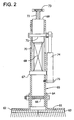
- a spring 68 which constitutes a compressible member having one end connected to the head assembly 61.
- the lower end of spring 68 engages the brush head assembly 61 via spring anchor 67.
- the other end of the spring 68 is connected to and rests against a support nut 69 of a linear actuator.
- the lower end of nut 69 engages the upper end of spring 68.
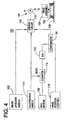
- the driving circuit 52 and comparator 54 constitute a motor controller which compares the voltages of the linear potentiometer 48 with the control panel potentiometer 52. There is a minimum and maximum voltage setting programmed into the controller. The controller will tell the actuator to stop if the linear potentiometer reaches one of these settings. Pressing the "up" position on switch 56 will override these settings thus allowing the actuator to raise the brush head off the floor.
- the controller is configured to have a voltage window setting that compares the voltages (or scaled value) of the linear potentiometer to the panel potentiometer. The window is set such that small variations or movements of the linear potentiometer will not cause the actuator to move. This is to prevent constant adjustment of the actuator.
- a comparator 24 or op-amp compares the signal provided by the position sensor 13 to a signal provided by the head position control 18. When these signals are nulled out or approximately equal, comparator 24 will provide a signal to the driving circuit 10 to discontinue energizing the motor 12. The driving circuit 10 will drive the head assembly up or down depending on which signal has a greater value. The comparator controls the driving circuit 10 to cause the motor 12 to rotate the screw driving the head assembly clockwise or counter clockwise to raise or lower the head assembly until its position matches the desired position as indicated by the control 18. If the operator sets control 18 to its maximum down position, the driving circuit 10 will drive the head assembly to its fully extended position.
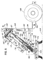
- the upper portion of the head assembly 105 includes the motor 112 which drives a motor shaft 140 for rotating a plurality of gears 142 which mesh with each other to rotate a screw 144.
- a traveling nut 146 threadably engaging the screw 144 is raised or lowered by rotation of the screw 144 as caused by the motor 112 rotating its motor shaft 140 to rotate the gears 142.
- the nut 146 is covered by an inner tube 148 which is crimped to and moves with the nut 146.
- the inner tube 148 has an upwardly extending portion 150 which extends above the top of the nut to partially cover the screw 144 and to act as a stop. When the nut 146 is in its highest position, portion 150 abuts against a housing 151 for gears 142 and prevents the nut 146 from moving upward.
- Fig. 7 is a graph illustrating the relationship between the pressure applied by the brush 106 to the surface of the floor 108, the current or torque driving the brush motor 166 and the position or actuator stroke of the brush 106 relative to the surface of floor 108.
- the z axis represents the amount of pressure being applied by the brush 106 to the surface floor 108.
Landscapes
- Vehicle Cleaning, Maintenance, Repair, Refitting, And Outriggers (AREA)
- Automatic Assembly (AREA)
- Finish Polishing, Edge Sharpening, And Grinding By Specific Grinding Devices (AREA)
- Prostheses (AREA)
- Magnetic Resonance Imaging Apparatus (AREA)
- Electrotherapy Devices (AREA)
- Brushes (AREA)
Abstract
Description
Claims (10)
- An apparatus for use on a surface and responsive to an operator, said apparatus comprising:a vehicle adapted to ride on the surface;a head assembly adapted to carry a device for engaging and treating the surface;a support;a connector assembly interconnecting the head assembly and the support;an actuator on the vehicle for raising and lowering the support relative to the surface;a sensor detecting a distance between the support and the head assembly;a head position control, responsive to input from the operator, indicating a desired position of the head assembly relative to the support; anda driving circuit responsive to the head position control and responsive to the sensor for energizing the actuator to raise and lower the support so that the distance between the support and the head assembly as detected by the sensor corresponds to the desired position as indicated by the head position control thereby controlling the relative engagement between the head assembly and the surface and thereby controlling the treatment of the surface by the head assembly.
- The apparatus of claim 1 wherein the sensor comprises a linear potentiometer.
- The apparatus of claims 1 or 2 wherein the head position control is a operator-controlled potentiometer and further comprising a comparator for comparing a voltage signal generated by the operator-controlled potentiometer to a voltage signal generated by the linear potentiometer, said comparator providing an output signal corresponding to the comparison to the driving circuit.
- The apparatus of claims 1-3 further comprising an up/down switch responsive to the operator and connected to the driving circuit for selectively controlling the actuator such that when the switch is in an UP position, the actuator is energized to raise the support and such that when the switch is in a DOWN position, the actuator is energized to lower the support.
- The apparatus of claims 1-4 wherein the connector assembly has a first end engaging the head assembly and having a second end engaging the support wherein a distance between the first end and the second end is variable.
- The apparatus of claims 1-5 further comprising:
a compressible member of variable length between the support and the head assembly; and
wherein the sensor comprises a linear sensor detecting a length of the compressible member. - The apparatus of claims 1-6:wherein the head position control comprises a position control responsive to operator input for indicating a head position of the device relative to the surface or range of head positions of the device relative to the surface, said head position or said range of head positions indicating a distance or range of distances, respectively, between the device and the surface; andwherein the driving circuit comprises a controller responsive to the position control for selectively actuating the actuator to maintain the device in the head position or within the range of head positions as indicated by the position control.
- The apparatus of claim 7 further comprising:wherein the controller is responsive to the torque control for providing a torque control signal to the input of the torque control circuit to maintain the motor at the desired torque or within the desired range of torques.a motor on the head assembly for rotating the device;a torque control circuit having an input receiving a signal for controlling the torque of the motor;a torque control responsive to operator input for indicating a desired torque or a desired range of torques for the motor; and
- The apparatus of claim 8 further comprising:wherein the controller is responsive to the pressure control and the pressure sensor for selectively actuating the actuator to maintain the pressure of the device on the surface at the desired pressure or within the desired range of pressures.a pressure sensor detecting the pressure of device on the surface;a pressure control responsive to operator input for indicating a desired pressure or a desired range of pressures for the device on the surface; and
- The apparatus of claim 7 further comprising:wherein the controller is responsive to the pressure control and the pressure sensor for selectively actuating the actuator to maintain the pressure of the device on the surface at the desired pressure or within the desired range of pressures.a pressure sensor detecting the pressure of device on the surface;a pressure control responsive to operator input for indicating a desired pressure or a desired range of pressures for the device on the surface; and
Applications Claiming Priority (2)
| Application Number | Priority Date | Filing Date | Title |
|---|---|---|---|
| US621034 | 2000-07-21 | ||
| US09/621,034 US6493896B1 (en) | 1998-10-22 | 2000-07-21 | Brush head positioning system |
Publications (3)
| Publication Number | Publication Date |
|---|---|
| EP1174074A2 true EP1174074A2 (en) | 2002-01-23 |
| EP1174074A3 EP1174074A3 (en) | 2004-04-07 |
| EP1174074B1 EP1174074B1 (en) | 2005-06-08 |
Family
ID=24488446
Family Applications (1)
| Application Number | Title | Priority Date | Filing Date |
|---|---|---|---|
| EP01116752A Expired - Lifetime EP1174074B1 (en) | 2000-07-21 | 2001-07-19 | Brush head positioning system |
Country Status (5)
| Country | Link |
|---|---|
| US (1) | US6493896B1 (en) |
| EP (1) | EP1174074B1 (en) |
| AT (1) | ATE297155T1 (en) |
| CA (1) | CA2353279C (en) |
| DE (1) | DE60111306T2 (en) |
Cited By (3)
| Publication number | Priority date | Publication date | Assignee | Title |
|---|---|---|---|---|
| WO2005107564A1 (en) * | 2004-05-07 | 2005-11-17 | William Anthony Briscoe | Surface working apparatus |
| WO2010110796A1 (en) * | 2009-03-26 | 2010-09-30 | Nilfisk-Advance, Inc. | Flow and scrubbing pressure control system and methods for surface treating apparatus |
| CN109199261A (en) * | 2017-06-30 | 2019-01-15 | 沈阳新松机器人自动化股份有限公司 | Scrubbing brush dish structure is washed in pressure automatic adjustment |
Families Citing this family (34)
| Publication number | Priority date | Publication date | Assignee | Title |
|---|---|---|---|---|
| US20020187133A1 (en) * | 1999-10-01 | 2002-12-12 | Hiroshi Kubota | Methods of isolating bipotent hepatic progenitor cells |
| US7456017B2 (en) * | 1999-10-01 | 2008-11-25 | University Of North Carolina At Chapel Hill | Processes for clonal growth of hepatic progenitor cells |
| WO2002094078A1 (en) * | 2001-05-21 | 2002-11-28 | Tennant Compagny | Suspension for a surface maintenance appliance |
| US7038416B2 (en) * | 2001-05-21 | 2006-05-02 | Tennant Company | Control system for a floor maintenance appliance |
| US6986185B2 (en) * | 2001-10-30 | 2006-01-17 | Applied Materials Inc. | Methods and apparatus for determining scrubber brush pressure |
| US20040200017A1 (en) * | 2003-04-10 | 2004-10-14 | Crane Joylon M. | Surface maintenance tool power control system |
| KR20120004551A (en) * | 2003-10-28 | 2012-01-12 | 어플라이드 머티어리얼스, 인코포레이티드 | Scrubber box and how to use it |
| US8234749B2 (en) * | 2005-01-11 | 2012-08-07 | Nilfisk-Advance, Inc. | Orbital scrubber with stabilizer element |
| US20060150362A1 (en) * | 2005-01-11 | 2006-07-13 | Alto U.S. Inc. | Orbital scrubber |
| WO2006078921A1 (en) * | 2005-01-18 | 2006-07-27 | Oceanetics, Inc. | Aquarium cleaner |
| US20070212983A1 (en) * | 2006-03-13 | 2007-09-13 | Applied Materials, Inc. | Apparatus and methods for conditioning a polishing pad |
| DE102007050351A1 (en) | 2007-10-11 | 2009-04-16 | Alfred Kärcher Gmbh & Co. Kg | Cleaning tool and cleaning device with such a cleaning tool |
| DE102008009221A1 (en) * | 2008-02-06 | 2009-08-13 | Alfred Kärcher Gmbh & Co. Kg | System for storing and dispensing liquid cleaning additive for high-pressure cleaning device |
| DE102008012209A1 (en) * | 2008-03-03 | 2009-09-10 | Krones Ag | Device for labeling containers |
| DE102009018121A1 (en) * | 2009-04-09 | 2010-10-14 | Alfred Kärcher Gmbh & Co. Kg | Method for operating a cleaning device and cleaning device and cleaning tool for performing the method |
| DE102009033944A1 (en) | 2009-07-14 | 2011-01-20 | Alfred Kärcher Gmbh & Co. Kg | Cleaning device and method for controlling access to a cleaning device |
| DE102010042347A1 (en) | 2010-10-12 | 2012-04-12 | Alfred Kärcher Gmbh & Co. Kg | Method for operating a cleaning device and cleaning device for carrying out the method |
| EP2814371B1 (en) * | 2012-02-16 | 2018-06-06 | Tennant Company | Surface maintenance vehicle with compact cleaning head lift mechanism and suspension |
| US8555450B1 (en) * | 2012-05-30 | 2013-10-15 | Christine A. Sabol | Residential wood floor cleaning machine |
| US9216440B2 (en) * | 2012-05-31 | 2015-12-22 | Becton, Dickinson And Company | Systems and methods to monitor proper disinfection of needleless connectors |
| SE541649C2 (en) * | 2016-06-14 | 2019-11-19 | Husqvarna Ab | Floor grinding machine and method of operating floor grinding machine |
| KR102137458B1 (en) | 2016-07-14 | 2020-07-24 | 엘지전자 주식회사 | Vacuum cleaner |
| WO2018012918A1 (en) | 2016-07-14 | 2018-01-18 | 엘지전자 주식회사 | Cleaner |
| KR101903022B1 (en) | 2016-07-14 | 2018-10-01 | 엘지전자 주식회사 | Robot Cleaner |
| WO2018012917A1 (en) | 2016-07-14 | 2018-01-18 | 엘지전자 주식회사 | Cleaner |
| WO2018012913A1 (en) | 2016-07-14 | 2018-01-18 | 엘지전자 주식회사 | Robotic cleaner |
| US11019975B2 (en) | 2016-07-14 | 2021-06-01 | Lg Electronics Inc. | Robot cleaner |
| KR102227373B1 (en) | 2016-07-14 | 2021-03-11 | 엘지전자 주식회사 | robotic vacuum |
| CN114224252B (en) * | 2016-07-14 | 2023-06-02 | Lg 电子株式会社 | robot cleaner |
| US11564546B2 (en) | 2016-07-14 | 2023-01-31 | Lg Electronics Inc. | Cleaner |
| CN108125632A (en) * | 2018-01-01 | 2018-06-08 | 吴为生 | Intelligent floor cleaner |
| CN112493948B (en) * | 2020-11-30 | 2024-04-12 | 追觅创新科技(苏州)有限公司 | Self-cleaning device and cleaning component detection method |
| CN112493932B (en) * | 2020-12-19 | 2021-09-17 | 山东鲁南大数据产业发展有限公司 | Electromechanical engineering workshop environment-friendly device based on aerodynamics |
| CN112741560B (en) * | 2020-12-30 | 2022-04-29 | 永康市宏奥工贸有限公司 | Ground cleaning device for cleaning robot |
Family Cites Families (6)
| Publication number | Priority date | Publication date | Assignee | Title |
|---|---|---|---|---|
| US4757566A (en) * | 1987-07-27 | 1988-07-19 | Tennant Company | Control of torque in floor maintenance tools by drive motor load |
| GB9703528D0 (en) * | 1996-09-04 | 1997-04-09 | Briscoe William A | Surface working apparatus |
| US6163915A (en) * | 1997-09-04 | 2000-12-26 | Minuteman International, Inc. | Control system for floor care machine |
| US6042656A (en) * | 1997-10-17 | 2000-03-28 | Nilfisk-Advance, Inc. | Shutoff control methods for surface treating machines |
| EP0910981A1 (en) * | 1997-10-22 | 1999-04-28 | Alto U.S. Inc. | Brush head positioning system |
| US5943724A (en) * | 1998-01-13 | 1999-08-31 | Tennant Company | Electro-hydraulic brush down force control |
-
2000
- 2000-07-21 US US09/621,034 patent/US6493896B1/en not_active Ceased
-
2001
- 2001-07-19 EP EP01116752A patent/EP1174074B1/en not_active Expired - Lifetime
- 2001-07-19 AT AT01116752T patent/ATE297155T1/en not_active IP Right Cessation
- 2001-07-19 DE DE60111306T patent/DE60111306T2/en not_active Expired - Lifetime
- 2001-07-19 CA CA002353279A patent/CA2353279C/en not_active Expired - Fee Related
Cited By (3)
| Publication number | Priority date | Publication date | Assignee | Title |
|---|---|---|---|---|
| WO2005107564A1 (en) * | 2004-05-07 | 2005-11-17 | William Anthony Briscoe | Surface working apparatus |
| WO2010110796A1 (en) * | 2009-03-26 | 2010-09-30 | Nilfisk-Advance, Inc. | Flow and scrubbing pressure control system and methods for surface treating apparatus |
| CN109199261A (en) * | 2017-06-30 | 2019-01-15 | 沈阳新松机器人自动化股份有限公司 | Scrubbing brush dish structure is washed in pressure automatic adjustment |
Also Published As
| Publication number | Publication date |
|---|---|
| EP1174074A3 (en) | 2004-04-07 |
| ATE297155T1 (en) | 2005-06-15 |
| EP1174074B1 (en) | 2005-06-08 |
| CA2353279C (en) | 2006-05-23 |
| CA2353279A1 (en) | 2002-01-21 |
| US6493896B1 (en) | 2002-12-17 |
| DE60111306D1 (en) | 2005-07-14 |
| DE60111306T2 (en) | 2006-03-23 |
Similar Documents
| Publication | Publication Date | Title |
|---|---|---|
| EP1174074B1 (en) | Brush head positioning system | |
| EP0910981A1 (en) | Brush head positioning system | |
| US11638669B2 (en) | Lift control systems for lifting devices and lifting devices comprising the same | |
| US5673450A (en) | Brush pressure system | |
| EP0301437B1 (en) | Control of torque in floor maintenance tools by drive motor load | |
| US6425169B1 (en) | Surface working apparatus | |
| US4286417A (en) | Blasting machine with position sensing and adjustment | |
| US7120961B2 (en) | Brush wear adjustment system and method | |
| USRE39581E1 (en) | Brush head positioning system | |
| EP0241694A1 (en) | Automatic tool force compensator for a surface maintenance machine | |
| EP1844640A1 (en) | An apparatus to adjust the reel-to-bedknife gap of a reel mower cutting unit and a method for adjusting the reel-to-bedknife gap or height-of cut on a cutting reel unit | |
| CN1036494A (en) | The automatic grinding system of forage harvester | |
| US7231757B2 (en) | Method and apparatus for setting and maintaining reel-to-bedknife clearance | |
| WO2017025093A1 (en) | Abrasion arrangement for sanding head | |
| WO2008128751A1 (en) | Method for operating a rotary brush arrangement and rotary brush arrangement for performing such a method | |
| EP0682856A2 (en) | A self-propelled machine with controlled-level implement | |
| US6351898B1 (en) | Height adjustment system | |
| EP0870265A4 (en) | ||
| US7193381B2 (en) | Electric jack ground contact detection method and device | |
| CN119679326B (en) | Floor scrubbers, floor scrubber control methods and floor scrubber systems | |
| DE102018119181A1 (en) | Suction nozzle for a vacuum cleaner and vacuum cleaner for cleaning a surface | |
| JP2834008B2 (en) | Method and apparatus for controlling screed height in asphalt finisher | |
| JP2572315Y2 (en) | Rotating brush lifting device | |
| KR20000003164U (en) | Stand line automatic adjustment device of skin pass mill | |
| JPH05316825A (en) | Rice transplanter |
Legal Events
| Date | Code | Title | Description |
|---|---|---|---|
| PUAI | Public reference made under article 153(3) epc to a published international application that has entered the european phase |
Free format text: ORIGINAL CODE: 0009012 |
|
| AK | Designated contracting states |
Kind code of ref document: A2 Designated state(s): AT BE CH CY DE DK ES FI FR GB GR IE IT LI LU MC NL PT SE TR |
|
| AX | Request for extension of the european patent |
Free format text: AL;LT;LV;MK;RO;SI |
|
| PUAL | Search report despatched |
Free format text: ORIGINAL CODE: 0009013 |
|
| AK | Designated contracting states |
Kind code of ref document: A3 Designated state(s): AT BE CH CY DE DK ES FI FR GB GR IE IT LI LU MC NL PT SE TR |
|
| AX | Request for extension of the european patent |
Extension state: AL LT LV MK RO SI |
|
| RIC1 | Information provided on ipc code assigned before grant |
Ipc: 7A 47L 11/40 B Ipc: 7A 47L 11/283 A |
|
| 17P | Request for examination filed |
Effective date: 20040915 |
|
| GRAP | Despatch of communication of intention to grant a patent |
Free format text: ORIGINAL CODE: EPIDOSNIGR1 |
|
| AKX | Designation fees paid |
Designated state(s): AT BE CH CY DE DK ES FI FR GB GR IE IT LI LU MC NL PT SE TR |
|
| GRAS | Grant fee paid |
Free format text: ORIGINAL CODE: EPIDOSNIGR3 |
|
| GRAA | (expected) grant |
Free format text: ORIGINAL CODE: 0009210 |
|
| AK | Designated contracting states |
Kind code of ref document: B1 Designated state(s): AT BE CH CY DE DK ES FI FR GB GR IE IT LI LU MC NL PT SE TR |
|
| PG25 | Lapsed in a contracting state [announced via postgrant information from national office to epo] |
Ref country code: AT Free format text: LAPSE BECAUSE OF FAILURE TO SUBMIT A TRANSLATION OF THE DESCRIPTION OR TO PAY THE FEE WITHIN THE PRESCRIBED TIME-LIMIT Effective date: 20050608 Ref country code: LI Free format text: LAPSE BECAUSE OF FAILURE TO SUBMIT A TRANSLATION OF THE DESCRIPTION OR TO PAY THE FEE WITHIN THE PRESCRIBED TIME-LIMIT Effective date: 20050608 Ref country code: ES Free format text: LAPSE BECAUSE OF FAILURE TO SUBMIT A TRANSLATION OF THE DESCRIPTION OR TO PAY THE FEE WITHIN THE PRESCRIBED TIME-LIMIT Effective date: 20050608 Ref country code: FI Free format text: LAPSE BECAUSE OF FAILURE TO SUBMIT A TRANSLATION OF THE DESCRIPTION OR TO PAY THE FEE WITHIN THE PRESCRIBED TIME-LIMIT Effective date: 20050608 Ref country code: BE Free format text: LAPSE BECAUSE OF FAILURE TO SUBMIT A TRANSLATION OF THE DESCRIPTION OR TO PAY THE FEE WITHIN THE PRESCRIBED TIME-LIMIT Effective date: 20050608 Ref country code: CH Free format text: LAPSE BECAUSE OF FAILURE TO SUBMIT A TRANSLATION OF THE DESCRIPTION OR TO PAY THE FEE WITHIN THE PRESCRIBED TIME-LIMIT Effective date: 20050608 Ref country code: TR Free format text: LAPSE BECAUSE OF FAILURE TO SUBMIT A TRANSLATION OF THE DESCRIPTION OR TO PAY THE FEE WITHIN THE PRESCRIBED TIME-LIMIT Effective date: 20050608 |
|
| REG | Reference to a national code |
Ref country code: GB Ref legal event code: FG4D |
|
| REG | Reference to a national code |
Ref country code: CH Ref legal event code: EP |
|
| REF | Corresponds to: |
Ref document number: 60111306 Country of ref document: DE Date of ref document: 20050714 Kind code of ref document: P |
|
| PG25 | Lapsed in a contracting state [announced via postgrant information from national office to epo] |
Ref country code: LU Free format text: LAPSE BECAUSE OF NON-PAYMENT OF DUE FEES Effective date: 20050719 Ref country code: IE Free format text: LAPSE BECAUSE OF NON-PAYMENT OF DUE FEES Effective date: 20050719 Ref country code: CY Free format text: LAPSE BECAUSE OF FAILURE TO SUBMIT A TRANSLATION OF THE DESCRIPTION OR TO PAY THE FEE WITHIN THE PRESCRIBED TIME-LIMIT Effective date: 20050719 |
|
| REG | Reference to a national code |
Ref country code: IE Ref legal event code: FG4D |
|
| PG25 | Lapsed in a contracting state [announced via postgrant information from national office to epo] |
Ref country code: MC Free format text: LAPSE BECAUSE OF NON-PAYMENT OF DUE FEES Effective date: 20050731 |
|
| PG25 | Lapsed in a contracting state [announced via postgrant information from national office to epo] |
Ref country code: SE Free format text: LAPSE BECAUSE OF FAILURE TO SUBMIT A TRANSLATION OF THE DESCRIPTION OR TO PAY THE FEE WITHIN THE PRESCRIBED TIME-LIMIT Effective date: 20050908 Ref country code: DK Free format text: LAPSE BECAUSE OF FAILURE TO SUBMIT A TRANSLATION OF THE DESCRIPTION OR TO PAY THE FEE WITHIN THE PRESCRIBED TIME-LIMIT Effective date: 20050908 Ref country code: GR Free format text: LAPSE BECAUSE OF FAILURE TO SUBMIT A TRANSLATION OF THE DESCRIPTION OR TO PAY THE FEE WITHIN THE PRESCRIBED TIME-LIMIT Effective date: 20050908 |
|
| PG25 | Lapsed in a contracting state [announced via postgrant information from national office to epo] |
Ref country code: PT Free format text: LAPSE BECAUSE OF FAILURE TO SUBMIT A TRANSLATION OF THE DESCRIPTION OR TO PAY THE FEE WITHIN THE PRESCRIBED TIME-LIMIT Effective date: 20051114 |
|
| REG | Reference to a national code |
Ref country code: CH Ref legal event code: PL |
|
| ET | Fr: translation filed | ||
| PLBE | No opposition filed within time limit |
Free format text: ORIGINAL CODE: 0009261 |
|
| STAA | Information on the status of an ep patent application or granted ep patent |
Free format text: STATUS: NO OPPOSITION FILED WITHIN TIME LIMIT |
|
| REG | Reference to a national code |
Ref country code: IE Ref legal event code: MM4A |
|
| 26N | No opposition filed |
Effective date: 20060309 |
|
| PG25 | Lapsed in a contracting state [announced via postgrant information from national office to epo] |
Ref country code: IT Free format text: LAPSE BECAUSE OF NON-PAYMENT OF DUE FEES Effective date: 20090719 |
|
| PGRI | Patent reinstated in contracting state [announced from national office to epo] |
Ref country code: IT Effective date: 20110616 |
|
| PGFP | Annual fee paid to national office [announced via postgrant information from national office to epo] |
Ref country code: FR Payment date: 20130717 Year of fee payment: 13 |
|
| REG | Reference to a national code |
Ref country code: FR Ref legal event code: ST Effective date: 20150331 |
|
| PG25 | Lapsed in a contracting state [announced via postgrant information from national office to epo] |
Ref country code: FR Free format text: LAPSE BECAUSE OF NON-PAYMENT OF DUE FEES Effective date: 20140731 |
|
| PGFP | Annual fee paid to national office [announced via postgrant information from national office to epo] |
Ref country code: NL Payment date: 20150826 Year of fee payment: 15 |
|
| PGFP | Annual fee paid to national office [announced via postgrant information from national office to epo] |
Ref country code: DE Payment date: 20150827 Year of fee payment: 15 Ref country code: GB Payment date: 20150827 Year of fee payment: 15 |
|
| PGFP | Annual fee paid to national office [announced via postgrant information from national office to epo] |
Ref country code: IT Payment date: 20150825 Year of fee payment: 15 |
|
| REG | Reference to a national code |
Ref country code: DE Ref legal event code: R119 Ref document number: 60111306 Country of ref document: DE |
|
| REG | Reference to a national code |
Ref country code: NL Ref legal event code: MM Effective date: 20160801 |
|
| GBPC | Gb: european patent ceased through non-payment of renewal fee |
Effective date: 20160719 |
|
| PG25 | Lapsed in a contracting state [announced via postgrant information from national office to epo] |
Ref country code: DE Free format text: LAPSE BECAUSE OF NON-PAYMENT OF DUE FEES Effective date: 20170201 Ref country code: NL Free format text: LAPSE BECAUSE OF NON-PAYMENT OF DUE FEES Effective date: 20160801 |
|
| PG25 | Lapsed in a contracting state [announced via postgrant information from national office to epo] |
Ref country code: GB Free format text: LAPSE BECAUSE OF NON-PAYMENT OF DUE FEES Effective date: 20160719 |
|
| PG25 | Lapsed in a contracting state [announced via postgrant information from national office to epo] |
Ref country code: IT Free format text: LAPSE BECAUSE OF NON-PAYMENT OF DUE FEES Effective date: 20160719 |