EP1172900A2 - Nonpolarized electrical connector assembly especially for use as automotive squib - Google Patents
Nonpolarized electrical connector assembly especially for use as automotive squib Download PDFInfo
- Publication number
- EP1172900A2 EP1172900A2 EP01305816A EP01305816A EP1172900A2 EP 1172900 A2 EP1172900 A2 EP 1172900A2 EP 01305816 A EP01305816 A EP 01305816A EP 01305816 A EP01305816 A EP 01305816A EP 1172900 A2 EP1172900 A2 EP 1172900A2
- Authority
- EP
- European Patent Office
- Prior art keywords
- receptacle
- contact
- plug
- contacts
- connector
- Prior art date
- Legal status (The legal status is an assumption and is not a legal conclusion. Google has not performed a legal analysis and makes no representation as to the accuracy of the status listed.)
- Withdrawn
Links
- 230000013011 mating Effects 0.000 claims abstract description 44
- 239000003999 initiator Substances 0.000 claims abstract description 32
- 239000004020 conductor Substances 0.000 claims description 5
- 230000002093 peripheral effect Effects 0.000 claims description 5
- 239000004697 Polyetherimide Substances 0.000 description 3
- 230000000712 assembly Effects 0.000 description 3
- 238000000429 assembly Methods 0.000 description 3
- 239000000463 material Substances 0.000 description 3
- 230000010287 polarization Effects 0.000 description 3
- 229920001601 polyetherimide Polymers 0.000 description 3
- 229910000859 α-Fe Inorganic materials 0.000 description 3
- 239000012212 insulator Substances 0.000 description 2
- 238000000034 method Methods 0.000 description 2
- 238000004891 communication Methods 0.000 description 1
- 238000005260 corrosion Methods 0.000 description 1
- 230000007797 corrosion Effects 0.000 description 1
- 230000008030 elimination Effects 0.000 description 1
- 238000003379 elimination reaction Methods 0.000 description 1
- 239000002360 explosive Substances 0.000 description 1
- 238000000605 extraction Methods 0.000 description 1
- 239000003721 gunpowder Substances 0.000 description 1
- 238000003780 insertion Methods 0.000 description 1
- 230000037431 insertion Effects 0.000 description 1
- 239000002184 metal Substances 0.000 description 1
- 239000004033 plastic Substances 0.000 description 1
- 229920003023 plastic Polymers 0.000 description 1
- 230000008054 signal transmission Effects 0.000 description 1
- 230000011664 signaling Effects 0.000 description 1
- 230000000087 stabilizing effect Effects 0.000 description 1
- 230000000153 supplemental effect Effects 0.000 description 1
Images


Classifications
-
- H—ELECTRICITY
- H01—ELECTRIC ELEMENTS
- H01R—ELECTRICALLY-CONDUCTIVE CONNECTIONS; STRUCTURAL ASSOCIATIONS OF A PLURALITY OF MUTUALLY-INSULATED ELECTRICAL CONNECTING ELEMENTS; COUPLING DEVICES; CURRENT COLLECTORS
- H01R24/00—Two-part coupling devices, or either of their cooperating parts, characterised by their overall structure
- H01R24/58—Contacts spaced along longitudinal axis of engagement
-
- H—ELECTRICITY
- H01—ELECTRIC ELEMENTS
- H01R—ELECTRICALLY-CONDUCTIVE CONNECTIONS; STRUCTURAL ASSOCIATIONS OF A PLURALITY OF MUTUALLY-INSULATED ELECTRICAL CONNECTING ELEMENTS; COUPLING DEVICES; CURRENT COLLECTORS
- H01R2105/00—Three poles
Definitions
- This invention is directed to electrical connectors comprising a plug and receptacle assembly for use in transmitting electrical signals on more than one signal path.
- This invention is more specifically directed to electrical connectors that do not require polarization.
- This electrical connector assembly employs axially spaced contacts in one connector and arcuately spaced contacts in a mating connector with the arcuately spaced contacts having axially spaced contact points to engage the axially spaced contacts in the mating electrical connector.
- This invention is also related to electrical connectors for use in automotive applications, such as electrical connectors for airbag inflation initiators or squibs.
- Vehicle airbag systems typically include an airbag unit mounted within the cabin of the vehicle, in order to protect the occupant in the event of an accident, and a deceleration or other sensor that is typically not in the vicinity of the inflatable airbag.
- an airbag inflation initiator or squib is activated in response to a signal from the sensor.
- the conventional squib unit typically contains an explosive material, such as gun powder, that is fired upon receipt of an electrical signal to cause the rapid release of high pressure gas to inflate the airbag.
- the squib is therefore typically part of the airbag unit.
- a squib electrical connector is normally mated to the airbag inflation initiator or squib in order to connect lead wires or other conductors leading from the sensor unit.
- the electrical connector system permits independent assembly of the airbag unit and the sensor or the remainder of the airbag system, and also permits subsequent connection and disconnection for servicing or repair.
- Conventional squib units typically employ two terminal pins and, when a current flows through both pins, the squib is activated and the airbag is inflated.
- the two pins are located side by side.
- a shorting bar is normally mounted on both pins and, when the squib connector is mated to the pins, the shorting bar is forced away from one of the pins.
- These conventional squib connector assemblies are also generally polarized so that the wrong pin is not connected to the sensor to permit inadvertent inflation of the airbag or to insure that the airbag will properly inflate upon receipt of a signal.
- US-A-6,029,995 shows a relatively recent example of a mechanism for inflating an airbag as part of a vehicle restraint system.
- US-A-5,435,754 and US-A-5,653,606 show two examples of electrical connectors that can be employed with conventional squib units.
- US-A-5,993,230 discloses a different technique in which a single pin connection is employed in conjunction with a surrounding electrically conductive annular ground plate so. that the plug connector can be attached, in what is termed, an orientationless fashion.
- One approach that has been considered for use with new smart airbag systems is to incorporate an active integrated circuit into the airbag unit or into the airbag inflation initiator or smart squib. This integrated circuit can then communicate with an external sensor or controller using two or three signal paths and the squib would be activated only upon receipt of a distinct signal pattern.
- the nonpolarized electrical connector assembly of the present invention provides a means for connecting an airbag inflation initiator or squib, including a smart squib, with an external sensor or controller over two or three or more signal lines.
- This connector assembly eliminates the need for polarization and shorting clips as well as the need for ferrites.
- the connector assembly can also fit within a smaller envelope than conventional squib connectors.
- the plug connector can be positioned at any angle relative to the mating axis between the plug connector and the receptacle connector.
- the receptacle connector can be mated with the airbag initiator eliminating the need to mount the connector terminals in the squib itself.
- the plug connector can also be latched to the receptacle connector in any 360° orientation.
- the connector assembly and the receptacle contacts are also suitable for transmitting signals of 50ma.
- the invention depicted herein, in the form of a preferred embodiment, is an electrical connector assembly and a receptacle connector subassembly that accomplishes each of these objectives and is adaptable to other applications and capabilities.
- a receptacle connector subassembly is used to connect a mating plug having axially spaced plug contacts to an electronic component subassembly such as an airbag inflation initiator or squib.
- the receptacle connector subassembly includes a receptacle housing and a plurality of electrical contacts or terminals.
- the housing is partially insertable into a cavity in the electronic component subassembly.
- This housing receptacle has a plug passage defined by a curved surface, which receives a mating plug.
- a plurality of slots extend axially along the curved surface, at arcuately spaced locations around the plug passage, and the receptacle contacts are inserted into these slots.
- Each receptacle contact has an electronic component mating section adjacent one end of the plug passage and a plug mating section closer to an opposite end of the respective receptacle contact.
- the plug mating sections of separate receptacle contacts are located at different axial positions in the plug passage so that individual receptacle contacts can each engage aligned ones of the axially spaced plug contacts when the mating plug is inserted into the plug passage of the receptacle housing.
- the mating plug need not be arcuately aligned relative to the individual receptacle contacts.
- a latch on the plug engages a latching shoulder on the receptacle housing for any mutual angular orientation between the plug and the receptacle.
- the receptacle is keyed relative to the electronic component or squib so that the receptacle terminals can be attached to leads or pins in the electronic component.
- the receptacle contacts employed in the preferred embodiment of this invention each have a resilient beam extending in one direction from a central mounting section. A contact point on the resilient beam is spaced from the mounting section.
- the mounting section secures the receptacle contact in a connector housing.
- the receptacle contact also has a resilient component contact section extending in an opposite direction from the central mounting section.
- the component contact section includes a contact slot open to one axial end of the receptacle contact.
- the component contact section is in the form of a C-channel or clip. Both the contact slot and the contact point on the resilient beam are offset in the same direction relative to the mounting section so that both the contact point and the contact slot will protrude in the same direction relative to the housing when the receptacle contact in mounted in the housing.
- the electrical connector assembly 10 comprising the preferred embodiment of this invention comprises a receptacle connector subassembly 20 and a plug connector subassembly 100.
- This electrical connector assembly 10 is intended to mate with an airbag inflation initiator or squib 2, as shown in Figure 1.
- This assembly 10 permits the plug connector subassembly 100 to be mated to the receptacle connector subassembly 20 in any angular orientation relative to the mating axis of the two connector subassemblies shown in Figure 1. It follows then that the plug connector 100 can be positioned in any angular orientation relative to the airbag initiator or squib 2. The plug connector 100 therefore need not be polarized relative to either the receptacle connector 20 or the squib 2.
- the connector assembly 10 could be employed with other devices, either in automotive or motor vehicle applications, or in any number of other applications that are not related to automotive applications.
- the airbag initiator or squib 2 referred to herein more generally as an electronic component or electronic component subassembly, with which this connector assembly 10 is employed, comprises a housing 4 having a cavity 5 extending into the housing 4 from an exposed face or end of the squib 2.
- Three electrical contact pins 6 extend perpendicularly relative to the cavity axis and across the cavity 5, as shown in Figure 2. These pins 6 are recessed relative to the exposed face of the housing 4.
- a polarizing key 7 is located along one side of the cylindrical cavity 5.
- This squib 2 is referred to as a smart squib because it incorporates an integrated circuit component (not shown) to activate the airbag initiator in response to signal transmitted to the integrated circuit component through the connector subassembly 10 and through pins 6 that are permanently connected to the integrated circuit component.
- Figure 1 shows a housing compartment 9 in which the integrated circuit component can be mounted.
- the receptacle connector subassembly 20 is mounted to the airbag initiator or squib 2, with the receptacle connector subassembly partially inserted and positioned in the cavity 5.
- the plug connector subassembly 100 is then mated to the receptacle subassembly 20 by inserting the plug post 106 with three cylindrical axially spaced plug contacts 102A, 102B, and 102C into the central plug passage or bore 38 extending into the cylindrical receptacle connector housing 22.
- Figure 3 shows the plug connector subassembly 100 mated to a freestanding receptacle connector subassembly 20. It should be understood that Figure 3 is intended merely for illustrative purposes and the plug connector subassembly 100 would not be mated to the receptacle connector subassembly 20 in this configuration. In practice, the receptacle connector subassembly 20 would be first mated to the airbag initiator or smart squib 2 and this combination would be mounted in a vehicle.
- FIG. 3 does demonstrate, however, the relative positions of the two connector subassemblies when mated and does show the latches 114 on the plug connector housing 104 as they engage a companion peripheral latching shoulder 34 on the exterior of the receptacle housing 22 to secure the plug connector subassembly 100 to both the receptacle connector subassembly 20 and the smart squib 2.
- Figures 4-6 show additional details of the receptacle connector subassembly 20, which comprises a molded receptacle housing 22 and three receptacle contacts 50A, 50B and 50C that are positioned in slots 42 surrounding a central plug passage or bore 38 that extends between an exterior face or end 24 and an interior housing end or face 26.
- the housing 22 is molded in one piece from a plastic material, such as a conventional polyetherimide (PEI) having high creep resistance.
- PEI polyetherimide
- the receptacle contacts or terminals 50A, 50B and 50C are stamped and formed, each in one piece, from a conventional spring metal, having a thickness of 0.25 mm, with contact areas appropriately plated for corrosion resistance and contact stability. The thickness of all of the contacts 50A, 50B, 50C is the same in the preferred embodiment of this invention.
- the molded receptacle housing 22 shown in Figures 4 and 7A-D has a toroidal configuration or cross section defined by a cylindrical outer surface and a central inner passage 38 defined by a generally cylindrical inwardly facing surface 40 which is interrupted by a series of axially extending slots 42.
- the central inner passage 38 is dimensioned to receive the post section 106 of the plug connector subassembly 100 so that electrical connector can be made with the three axially spaced plug contacts 102A, 102B, and 102C extending concentrically around the plug post 106.
- the three axially extending slots 42 are dimensioned to mount the three receptacle contacts 50A, 50B, and 50C at three arcuately spaced locations on half of the cylindrical surface 40.
- Receptacle contact 50A is positioned ninety degrees from receptacle contact 50C which, in turn, is positioned ninety degrees from receptacle contact 50B, which is opposed to contact 50A.
- the central plug receiving passage 38 extends between opposite end faces or surfaces 24, 26 on the receptacle housing 22.
- Interior housing face 24 will be positioned adjacent the base of the cavity 5 when the receptacle connector subassembly 20 is mated to the squib 2.
- the exterior housing end face 26 will extend beyond the squib housing 4 when the receptacle connector subassembly 20 is fully mated to the squib 2.
- a polarizing notch 36 extends into the exterior cylindrical face of the receptacle housing 22 adjacent to the interior face 24 and opposite from the slot 42 in which the short receptacle contact 50C is positioned. This polarizing notch 36 receives the polarizing key 7 on the squib housing 4.
- the receptacle connector subassembly 20 is polarized or keyed relative to the airbag initiator 2 so that the receptacle contacts 50A, 50B and 50C are properly positioned in alignment with the corresponding pins 6. It should be understood, however, that while the receptacle connector subassembly is keyed, polarized or properly angularly positioned relative to the squib 2, the plug connector subassembly 100 still does not have to be polarized or keyed or angularly oriented or aligned with either the receptacle connector subassembly 20 or the airbag initiator 2.
- the cylindrical or toroidal receptacle housing 22 has four sectors, all of which form a single one piece molded body.
- the first or lower housing sector 28 located adjacent to the interior face 24 has the largest outer dimension. It is this first section that will be received in the cavity 5 when the receptacle connector subassembly 20 is mated to the squib airbag initiator 2, and the polarizing notch 36 is located in this housing sector 28.
- An adjacent second housing sector 32 has a smaller external diameter and a next adjacent third housing sector 34 has the smallest outer diameter on the housing 22.
- a lip or ring 34 is located at the exterior end 26 of the housing 22, and this ring 34 has a larger outer diameter than the sector 32 to which it is adjacent.
- This ring 34 serves as a latching shoulder that is engaged by a plug latch 114 when the plug connector subassembly 100 is mated to the receptacle connector subassembly 20.
- the smaller sector 32 provides clearance for the plug latch 114. Since the shoulder or ring 34 extends completely around the periphery of the receptacle housing 22, the plug latch 114 can engage the shoulder 34 at any angular position so that the plug connector subassembly can be mated in any angular orientation and is free to rotate once mated.
- Each of the receptacle contacts 50A, 50B and 50C can be positioned in the receptacle housing 20 by inserting the contacts from the interior housing end 24 into the slots 42 located along the inwardly facing curved passage surface 40.
- Each of the slots 42 is recessed relative to the curved surface 40 and thus extends radially outward from this inwardly facing surface 40.
- Sidewalls 44 define the slots 42 and ribs 46 on the walls 44 serve to restrict the receptacle contacts after they have been inserted behind the ribs 46.
- Each of the receptacle contacts 50A, 50B and 50C has a mounting section 82 with teeth 84 extending from opposite edges of the mounting section 82.
- each of the receptacle contacts will have a contact point or area 58 located between outer housing faces 24, 26 at opposite ends of the housing 22.
- Electronic component contact sections 62 located on one end of each receptacle contact 50A, 50B and 50C will protrude beyond the interior receptacle housing face 24 so that these component contact sections 62 will be in position to engage the pins 6 extending perpendicular to the axis of the plug passage 38 and the cavity 5 in the initiator 2.
- Each of the stamped and formed contacts 50A, 50B and 50C has a resilient cantilever contact beam 56 extending from the central contact mounting section 82 toward a free end 54 that will be facing the exterior end of the receptacle contact.
- contact free end 54 will be the first portion of the contact to engage the plug connector when it is inserted into plug passage 38.
- a raised contact point or area 58 is located adjacent the free end 54 and comprises the innermost part of each receptacle contact 50A, 50B and 50C so that it will engage a corresponding and aligned plug contact 102A, 102B, and 102C extending around the periphery of the plug post or pin 106.
- the cantilever contact beam When the contact point 58 engages the plug contact 102A, 102B, or 102C, the cantilever contact beam is flexed generating a contact force sufficient to maintain a reliable contact between the plug contacts and the corresponding receptacle contact 50A, 50B or 50C.
- the cantilever beams 56 on different receptacle contacts have different lengths so that the axial positions of the contact points 58 on different receptacle contacts 50A, 50B and 50C will be mutually axially spaced or offset. In this way individual receptacle contacts 50A, 50B and 50C will engage different axially spaced plug contacts 102A, 102B, and 102C when the plug connector 100 is properly mated with the receptacle connector 20.
- a long receptacle contact 50A has the longest cantilever beam 56 so that its contact point 58 will be closest to the exterior end 26 of the receptacle connector where it will engage a peripheral plug contact 102A closest to the exterior receptacle end 26.
- a middle receptacle contact 50B has a somewhat shorter cantilever beam 56 so that its contact point 58 will engage a middle plug contact 102B.
- Short receptacle contact 50C has the shortest cantilever beam 56 so that it will be aligned with the first plug contact 102C to be inserted into the plug passage 30 as the two connectors are mated. Since the plug contacts 102 extend completely around the plug housing, it is only the axial positions of the plug contacts 102 A, 102B, 102C and the receptacle contacts 50A, 50B, 50C that result in mating between corresponding contacts.
- the three receptacle contacts 50A, 50B and 50C each have a resilient electronic component mating section 62 on the opposite side of the mounting section 82 from the resilient cantilever contact beam 56.
- Each of these component mounting sections 62 comprise a C-channel or C-clip for engaging one of the parallel pins 6 in the squib component 2.
- the long receptacle contact 50A and the middle receptacle contact 50B have identical C-channel contact sections 62 because these contacts are positioned so that the corresponding pin 6 will extend generally tangent to the mounting section 82 and the resilient beam 56.
- These receptacle contacts 50A and 50B are positioned opposite each other with the short receptacle contact 50C located between the other two receptacle contacts.
- the short receptacle contact 50C is thereof positioned so that its the central component pin extends generally perpendicular to the plate of the mounting section 82 and the cantilever beam 56 on the short receptacle contact 50C.
- Each receptacle component contact section 62 does have at least one component contact slot 66 open on one end of the receptacle contact and extending axially relative to the receptacle contact and to the central passage or bore 38. Pins 6 will therefore be aligned with and received in corresponding slots 66 when the receptacle contact is mated with the squib component 2.
- the long receptacle contact 50A and the middle receptacle contact 50B each has two slotted flat plate sections 68 extending inwardly from one end of the spaced flat plate 68. Slots 66 formed in these flat plate sections 68 have one edge with a recessed portion in which one of the pins 6 will fit so that a reliable electrical connector can be made between the receptacle contacts 50A and 50B and the corresponding pins 6. Force is required to either insert the pins 6 or remove the pins 6 from the slots 66.
- the slots 66 in the two flat plate sections 68 are aligned and the two flat plate sections 68 are joined by a central section 70 which joins the component contact section 62 to the remainder of the receptacle contact 50A or 50B.
- the central section 70 is joined to an offset section 60 between the mounting section 82 so that the component contact section 62 and the contact point 58 will both be on the same side of the mounting section. Both the component contact section 62 and the cantilever beam contact point 58 will then extend inwardly relative to the curved housing wall 40 into the plug passage 38.
- the short receptacle contact 50C also has a component contact section 62 formed by two flat plate sections 74 bent at right angles relative to a central flat plate section 72 to form a U-shaped configuration.
- the component slot 66 in the short receptacle contact 50C is however located in the central flat plate section 72 so that it will be properly oriented relative to a pin extending perpendicular to the stamped and formed short receptacle contact mounting section and resilient cantilever beam.
- the central flat plate section 72 is also joined to an offset section 60 so that both the short receptacle contact component mating section 62 and the resilient contact beam 56 will be positioned to extend into the plug passage or bore 38 when mounted in the corresponding housing slot 42.
- the plug connector subassembly 100 comprises a plug housing 104, also molded from a polyetherimide material, and three peripheral plug contacts 102A, 102B, 102C spaced axially along a central plug housing post 106.
- the cylindrical post 106 extends from a larger plug cap 108 having a larger outer diameter.
- a bore 110 extends through the plug post 106 and joins three conductor passageways 120 through which individual conductors or wires (not shown) can be inserted so that the wires can be terminated to respective plug contacts 102A, 102B, and 102C.
- the cylindrical plug contacts 102A, 102B, and 102C are located on the exterior surface of the post 106 where they will contact the contact points 58 on receptacle contacts 50A, 50B and 50C when the plug connector subassembly 100 is fully inserted into the plug passage 38 in the receptacle connector subassembly 20.
- Adjacent plug contacts 102A, 102B, and 102C are spaced apart by gaps and the endmost plug contact is spaced from the leading edge 112 of the post which first enters the receptacle housing 22.
- Two molded plug latches 114 extend from the periphery of the plug cap 108 and a radial gap is formed between each latch 114 and the opposed plug post 106 having a smaller outer diameter.
- Each latch 114 has a flexible latch beam 116 with an inwardly facing latch boss 118 located on the distal end of the latch beam 116.
- the latches 114 are configured so that the latch bosses 118 engage the peripheral latching shoulder 34 on the receptacle connector housing 22 to secure the plug connector subassembly 100 to its mating receptacle subassembly 20.
- the latch and the latching shoulder engage regardless of the angular orientation of the connector subassemblies.
- This preferred connector assembly 10 which is representative of other equivalent configurations, is capable of supplying either two or three signal transmission lines to and/or from an electronic component, such as an airbag inflation initiator or squib 2, using only a single male connecting member or plug post 106 and does not require polarization, keying or alignment of the plug connector assembly 100 relative to electronic component 2, the receptacle contacts 50A, 50B or 50C or the receptacle connector subassembly 20. No shorting bars are required for this connector assembly.
- the long receptacle contact 50A mates with the uppermost plug contact 102A, and this pair of terminals comprises a first signal path.
- the middle receptacle contact 50B mates with the middle plug contact 102B, and this pair of terminals comprises a second signal path.
- the short receptacle contact 50C mates with the lowermost plug contact 102C, and this pair of terminals comprise a third signal contact.
- one of these signal paths could be dedicated to ground or could supply a timing signal or could comprise a path for other purposes.
- signals of 50ma are transmitted on these signal paths.
- This connector assembly also has a relatively small size or envelope. For instance, the mated plug and receptacle connector assembly has a length of 9.5 mm and a maximum outside diameter of 6.2 mm.
- the plug connector 100 can be mated with to the receptacle connector subassembly 20 without stubbing and the contacts have excellent floating characteristics. These characteristics make the connector assembly 10 especially suitable for use as a squib or airbag inflation initiator connector, but the basic connector system can be used for other automotive as well as nonautomotive applications. This invention is also not limited to the use of two or three plug and receptacle contacts and is suitable for use with more that three contacts.
- FIG. 9-14 A second embodiment of an electrical connector assembly for use in a squib or airbag inflator assembly is shown in Figures 9-14.
- the main difference between the first and second embodiments is the respective orientation of the plug and receptacle contacts.
- the plug contacts face radially outward and the receptacle contacts face radially inward.
- the plug contacts face radially inward and the receptacle contacts face radially outward.
- the plug contacts are not exposed and are less likely to come into inadvertent contact with other components or equipment.
- Figure 9 shows the alternative version of the airbag inflation initiator or squib 202 with the alternative connector plug 300 mated to the alternative connector receptacle or socket 220.
- Receptacle 220 can be mounted in the squib 202 in the same manner as for the other embodiment, and the squib component 202 can indeed be identical to the first embodiment of the squib connector.
- the plug 300 is latched to the receptacle 220 by latches 314.
- Figures 10 and 11 show the connector receptacle assembly 220 that includes a molded receptacle housing 222 and three receptacle contacts 250A-C.
- the molded housing 222 is generally cylindrical in shape and has an interior face 224 which will be inserted into a squib component cavity in the same fashion as in the first embodiment.
- An opposite exterior face 226 will be exposed so that the plug 300 can be mated to the receptacle 220.
- the receptacle housing 222 includes a cylindrical support column 230 that extends to the exterior face 226.
- This support column has a cylindrical outer surface 240 with an annular passage 238 extending between the central support column 230 and the exterior wall of the housing 220.
- Three axial slots 242 extend along the support column 230, and the receptacle contacts 250A-C are positioned within these axial slots.
- the receptacle contacts 250A-C are inserted into the receptacle or socket housing 222 and the axial slots 242 through the interior face 224, as generally represented in Figure 10.
- the three receptacle contacts 250A-C are similar to the receptacle contacts 50A-C, but they are configured so that the receptacle contacts 250A-C can be oriented to face outwardly along cylindrical surface 240, rather then inwardly as in the first embodiment.
- Each of the three receptacle contacts 250A-C includes a cantilever beam contact section 254 and a mating section 262 on opposite sides of a mounting section 282.
- the cantilever beams extend into the annular channel passage 238 where they will mate with plug contacts 302A-C in a manner that will be subsequently discussed in more detail.
- each receptacle contact includes at least one mating channel 266 that can be clipped or snapped onto contact pins in the squib electronic component in the same manner as in the first embodiment.
- the mounting section 282 of each receptacle contact includes teeth that engage the side walls of the corresponding axial slot 242 to secure the contact within the slot 242 and to the support column 230.
- the lengths of the cantilever beams 254 are different and form a long receptacle contact 250A, a middle receptacle contact 250B and a short receptacle contact 250C. The contact area of these three receptacle contacts 250A-C is then axially staggered in much the same manner as in the first embodiment.
- Plug 300 includes three plug contacts 302A-C mounted in a molded plug housing 304.
- the plug housing 304 includes a plug housing base 326 and a plug housing cover 332.
- the housing base has three side by side channels 328.
- a cylindrical plug silo 306 extends from an outer side of the plug housing and a silo bore 310 extends through the silo 306 and into communication with each of the three channels 328. Portions of the plug contacts 302A-C are positioned in the channels 328, while other portions extend into the silo bore 310.
- Each of the plug contacts 302A-C includes a cylindrical band contact section 322A-C, respectively, that forms the mating section that is engaged by the corresponding receptacle terminal or contact when the plug connector 300 is mated to the receptacle connector 220. Wires are terminated to the individual plug contacts 302A-C by plug contact crimp sections 324A-C.
- the intermediate plug contact sections joining crimp sections 324A-C to cylindrical bands 322A-C are of different lengths, so that the individual cylindrical bands 322A-C can be axially staggered within the silo bore 310.
- the cylindrical bands 322A-C are stacked in axial alignment, with cylindrical insulator rings 330A-B positioned between adjacent cylindrical bands 322A-C, as shown in Figure 12.
- the plug contacts 302A-C stacked in the manner shown in Figure 13, the stacked band sections 322A-C can be inserted into the silo bore 310.
- the remaining portions of the plug contacts 302A-C, including the crimp sections 324A-C are then positioned within the channels 328 and the cover 332 is mated to the base 326 to form the completed plug assembly 300.
- Figure 14 shows that the cylindrical band sections 322A-C are positioned on an inwardly facing cylindrical surface of the surrounding silo 306 so that the band sections 322A-C are exposed in the silo bore 310.
- the relative lengths of the contacts will insure that that plug contact 302A can only mate with receptacle contact 250A, that plug contact 302B can only mate with receptacle contact 250B and that plug contact 302C can only mate with receptacle contact 302C.
- first and second embodiments may differ, each forms a nonpolarized connector assembly that can be mated no matter what the mutual angular orientation of one connector to the other.
- These alternative connector assemblies are therefore representative of other configurations employing the same or equivalent elements as would be understood by one of ordinary skill in the art. Therefore this invention is not limited to the preferred embodiments depicted herein, but is instead defined by the following claims.
Abstract
Description
- This invention is directed to electrical connectors comprising a plug and receptacle assembly for use in transmitting electrical signals on more than one signal path. This invention is more specifically directed to electrical connectors that do not require polarization. This electrical connector assembly employs axially spaced contacts in one connector and arcuately spaced contacts in a mating connector with the arcuately spaced contacts having axially spaced contact points to engage the axially spaced contacts in the mating electrical connector. This invention is also related to electrical connectors for use in automotive applications, such as electrical connectors for airbag inflation initiators or squibs.
- Vehicle airbag systems typically include an airbag unit mounted within the cabin of the vehicle, in order to protect the occupant in the event of an accident, and a deceleration or other sensor that is typically not in the vicinity of the inflatable airbag. In order to deploy the airbag, an airbag inflation initiator or squib is activated in response to a signal from the sensor. The conventional squib unit typically contains an explosive material, such as gun powder, that is fired upon receipt of an electrical signal to cause the rapid release of high pressure gas to inflate the airbag. The squib is therefore typically part of the airbag unit. A squib electrical connector is normally mated to the airbag inflation initiator or squib in order to connect lead wires or other conductors leading from the sensor unit. The electrical connector system permits independent assembly of the airbag unit and the sensor or the remainder of the airbag system, and also permits subsequent connection and disconnection for servicing or repair.
- Conventional squib units typically employ two terminal pins and, when a current flows through both pins, the squib is activated and the airbag is inflated. Typically, the two pins are located side by side. To prevent inadvertent actuation of the squib, a shorting bar is normally mounted on both pins and, when the squib connector is mated to the pins, the shorting bar is forced away from one of the pins. These conventional squib connector assemblies are also generally polarized so that the wrong pin is not connected to the sensor to permit inadvertent inflation of the airbag or to insure that the airbag will properly inflate upon receipt of a signal. In some cases, ferrites are also added to the interconnection system to prevent unwanted frequencies due to external interference. US-A-6,029,995 shows a relatively recent example of a mechanism for inflating an airbag as part of a vehicle restraint system. US-A-5,435,754 and US-A-5,653,606 show two examples of electrical connectors that can be employed with conventional squib units. US-A-5,993,230 discloses a different technique in which a single pin connection is employed in conjunction with a surrounding electrically conductive annular ground plate so. that the plug connector can be attached, in what is termed, an orientationless fashion.
- The evolution of passive or supplemental vehicle restraint systems, such as airbags, has led to use of airbags in areas other than the vehicle dash. Side cushion airbags and smaller airbags protecting against other eventualities have been proposed and introduced. In some cases, these other airbags must be assembled as a smaller unit, which has resulted in a demand for smaller electrical connector assemblies for use with these newer devices. In some cases, these airbags must be mounted in areas, such as door panels, where space is limited. Therefore, there is a need to eliminate the polarity or specific orientation of the electrical connector so that the airbag assembly will either fit in certain areas or can be assembled without excessive effort. Elimination of shorting clips and ferrites is also desirable if for no other reason than to eliminate the cost associated with those additional devices. One approach that has been considered for use with new smart airbag systems is to incorporate an active integrated circuit into the airbag unit or into the airbag inflation initiator or smart squib. This integrated circuit can then communicate with an external sensor or controller using two or three signal paths and the squib would be activated only upon receipt of a distinct signal pattern.
- The nonpolarized electrical connector assembly of the present invention provides a means for connecting an airbag inflation initiator or squib, including a smart squib, with an external sensor or controller over two or three or more signal lines. This connector assembly eliminates the need for polarization and shorting clips as well as the need for ferrites. The connector assembly can also fit within a smaller envelope than conventional squib connectors. The plug connector can be positioned at any angle relative to the mating axis between the plug connector and the receptacle connector. The receptacle connector can be mated with the airbag initiator eliminating the need to mount the connector terminals in the squib itself. The plug connector can also be latched to the receptacle connector in any 360° orientation. The connector assembly and the receptacle contacts are also suitable for transmitting signals of 50ma. The invention depicted herein, in the form of a preferred embodiment, is an electrical connector assembly and a receptacle connector subassembly that accomplishes each of these objectives and is adaptable to other applications and capabilities.
- A receptacle connector subassembly, according to one aspect of this invention, is used to connect a mating plug having axially spaced plug contacts to an electronic component subassembly such as an airbag inflation initiator or squib. The receptacle connector subassembly includes a receptacle housing and a plurality of electrical contacts or terminals. The housing is partially insertable into a cavity in the electronic component subassembly. This housing receptacle has a plug passage defined by a curved surface, which receives a mating plug. A plurality of slots extend axially along the curved surface, at arcuately spaced locations around the plug passage, and the receptacle contacts are inserted into these slots. Each receptacle contact has an electronic component mating section adjacent one end of the plug passage and a plug mating section closer to an opposite end of the respective receptacle contact. The plug mating sections of separate receptacle contacts are located at different axial positions in the plug passage so that individual receptacle contacts can each engage aligned ones of the axially spaced plug contacts when the mating plug is inserted into the plug passage of the receptacle housing. The mating plug need not be arcuately aligned relative to the individual receptacle contacts. In the preferred embodiment, a latch on the plug engages a latching shoulder on the receptacle housing for any mutual angular orientation between the plug and the receptacle. The receptacle is keyed relative to the electronic component or squib so that the receptacle terminals can be attached to leads or pins in the electronic component.
- The receptacle contacts employed in the preferred embodiment of this invention each have a resilient beam extending in one direction from a central mounting section. A contact point on the resilient beam is spaced from the mounting section. The mounting section secures the receptacle contact in a connector housing. The receptacle contact also has a resilient component contact section extending in an opposite direction from the central mounting section. The component contact section includes a contact slot open to one axial end of the receptacle contact. In the preferred embodiment of this invention, the component contact section is in the form of a C-channel or clip. Both the contact slot and the contact point on the resilient beam are offset in the same direction relative to the mounting section so that both the contact point and the contact slot will protrude in the same direction relative to the housing when the receptacle contact in mounted in the housing.
- In order that the present invention may be more readily understood, embodiments thereof will now be described with reference to the accompanying drawings, in which:-
- Figure 1 is an exploded view of the components of the squib electrical connector assembly and an airbag inflation initiator or squib to which the electrical connector can be mated in any angular orientation about a central axis.
- Figure 2 is a top view of the airbag inflation initiator housing showing a cavity in which the electrical connector receptacle can be inserted.
- Figure 3 is a view showing the plug connector subassembly and the receptacle connector subassembly in a mated configuration. Portions of the receptacle contacts that would otherwise be hidden in this view are shown in conjunction with the location of plug contact areas in this wireframe style drawing to show the manner in which the receptacle contacts engage axially spaced plug contacts.
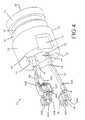
- Figure 4 is a view of the receptacle connector subassembly with three receptacle contacts shown in an exploded position relative to the receptacle connector housing.
- Figure 5A is a side view of a long receptacle contact.
- Figure 5B is a side view of a middle receptacle contact.
- Figure 5C is a side view of a short receptacle contact.
- Figure 6 is a three dimensional view of short receptacle contact.
- Figure 7A is a three dimensional view of the receptacle housing.
- Figure 7B is a bottom view of the receptacle housing.
- Figure 7C is a side view of the receptacle housing.
- Figure 7D is a section view of the receptacle housing taken along section lines 7D-7D in Figure 7A.
- Figure 8 is a view of the plug connector subassembly.
- Figure 9 is a view of an alternative embodiment of a smart squib electrical connector assembly and the squib initiator with which the connector assembly is used, showing the connector socket positioned in the squib initiator and the connector plug mated to the connector socket.
- Figure 10 is an exploded view of the connector socket of the alternative embodiment, showing three socket contacts positioned for insertion through an interior end of the socket or receptacle housing.
- Figure 11 is a view of the assembled connector socket of Figure 10, showing the mating end of the socket with the socket contacts exposed to mate with the connector plug.
- Figure 12 is an exploded view of the alternative embodiment of the connector plug used in the assembly of Figure 9
- Figure 13 is another exploded view of the alternative embodiment of the connector plug with the three plug contacts and separating insulators shown in a partially assembled configuration; and
- Figure 14 is a view the plug connector assembly after it has been assembled, with the plug contacts shown on the interior of a plug silo.
-
- The
electrical connector assembly 10 comprising the preferred embodiment of this invention comprises areceptacle connector subassembly 20 and aplug connector subassembly 100. Thiselectrical connector assembly 10 is intended to mate with an airbag inflation initiator orsquib 2, as shown in Figure 1. Thisassembly 10 permits theplug connector subassembly 100 to be mated to thereceptacle connector subassembly 20 in any angular orientation relative to the mating axis of the two connector subassemblies shown in Figure 1. It follows then that theplug connector 100 can be positioned in any angular orientation relative to the airbag initiator orsquib 2. Theplug connector 100 therefore need not be polarized relative to either thereceptacle connector 20 or thesquib 2. Although primarily intended for use as a squib connector, theconnector assembly 10 could be employed with other devices, either in automotive or motor vehicle applications, or in any number of other applications that are not related to automotive applications. - The airbag initiator or
squib 2, referred to herein more generally as an electronic component or electronic component subassembly, with which thisconnector assembly 10 is employed, comprises a housing 4 having acavity 5 extending into the housing 4 from an exposed face or end of thesquib 2. Three electrical contact pins 6 extend perpendicularly relative to the cavity axis and across thecavity 5, as shown in Figure 2. Thesepins 6 are recessed relative to the exposed face of the housing 4. Apolarizing key 7 is located along one side of thecylindrical cavity 5. Thissquib 2 is referred to as a smart squib because it incorporates an integrated circuit component (not shown) to activate the airbag initiator in response to signal transmitted to the integrated circuit component through theconnector subassembly 10 and throughpins 6 that are permanently connected to the integrated circuit component. Figure 1 shows ahousing compartment 9 in which the integrated circuit component can be mounted. - Electrical connection to the
squib 2 is provided by the two partelectrical connector assembly 10. Thereceptacle connector subassembly 20 is mounted to the airbag initiator orsquib 2, with the receptacle connector subassembly partially inserted and positioned in thecavity 5. In order to connect an external sensor or other signaling device to the airbag initiator orsquib 2, theplug connector subassembly 100 is then mated to thereceptacle subassembly 20 by inserting theplug post 106 with three cylindrical axially spacedplug contacts receptacle connector housing 22. Figure 3 shows theplug connector subassembly 100 mated to a freestandingreceptacle connector subassembly 20. It should be understood that Figure 3 is intended merely for illustrative purposes and theplug connector subassembly 100 would not be mated to thereceptacle connector subassembly 20 in this configuration. In practice, thereceptacle connector subassembly 20 would be first mated to the airbag initiator orsmart squib 2 and this combination would be mounted in a vehicle. Theplug connector subassembly 100, and the harness wires to which it would be attached, would only be mated to the previously positionedreceptacle connector subassembly 20 as part of a later assembly operation or a later repair or servicing procedure. Figure 3 does demonstrate, however, the relative positions of the two connector subassemblies when mated and does show thelatches 114 on theplug connector housing 104 as they engage a companion peripheral latchingshoulder 34 on the exterior of thereceptacle housing 22 to secure theplug connector subassembly 100 to both thereceptacle connector subassembly 20 and thesmart squib 2. - Figures 4-6 show additional details of the
receptacle connector subassembly 20, which comprises a moldedreceptacle housing 22 and threereceptacle contacts slots 42 surrounding a central plug passage or bore 38 that extends between an exterior face or end 24 and an interior housing end orface 26. In the preferred embodiment, thehousing 22 is molded in one piece from a plastic material, such as a conventional polyetherimide (PEI) having high creep resistance. The receptacle contacts orterminals contacts - The molded
receptacle housing 22 shown in Figures 4 and 7A-D has a toroidal configuration or cross section defined by a cylindrical outer surface and a centralinner passage 38 defined by a generally cylindrical inwardly facingsurface 40 which is interrupted by a series of axially extendingslots 42. The centralinner passage 38 is dimensioned to receive thepost section 106 of theplug connector subassembly 100 so that electrical connector can be made with the three axially spacedplug contacts plug post 106. The three axially extendingslots 42 are dimensioned to mount the threereceptacle contacts cylindrical surface 40.Receptacle contact 50A is positioned ninety degrees fromreceptacle contact 50C which, in turn, is positioned ninety degrees fromreceptacle contact 50B, which is opposed to contact 50A. - The central
plug receiving passage 38 extends between opposite end faces or surfaces 24, 26 on thereceptacle housing 22.Interior housing face 24 will be positioned adjacent the base of thecavity 5 when thereceptacle connector subassembly 20 is mated to thesquib 2. The exteriorhousing end face 26 will extend beyond the squib housing 4 when thereceptacle connector subassembly 20 is fully mated to thesquib 2. Apolarizing notch 36 extends into the exterior cylindrical face of thereceptacle housing 22 adjacent to theinterior face 24 and opposite from theslot 42 in which theshort receptacle contact 50C is positioned. Thispolarizing notch 36 receives thepolarizing key 7 on the squib housing 4. Thereceptacle connector subassembly 20 is polarized or keyed relative to theairbag initiator 2 so that thereceptacle contacts squib 2, theplug connector subassembly 100 still does not have to be polarized or keyed or angularly oriented or aligned with either thereceptacle connector subassembly 20 or theairbag initiator 2. - The cylindrical or
toroidal receptacle housing 22 has four sectors, all of which form a single one piece molded body. The first orlower housing sector 28 located adjacent to theinterior face 24 has the largest outer dimension. It is this first section that will be received in thecavity 5 when thereceptacle connector subassembly 20 is mated to thesquib airbag initiator 2, and thepolarizing notch 36 is located in thishousing sector 28. An adjacentsecond housing sector 32 has a smaller external diameter and a next adjacentthird housing sector 34 has the smallest outer diameter on thehousing 22. A lip orring 34 is located at theexterior end 26 of thehousing 22, and thisring 34 has a larger outer diameter than thesector 32 to which it is adjacent. Thisring 34 serves as a latching shoulder that is engaged by aplug latch 114 when theplug connector subassembly 100 is mated to thereceptacle connector subassembly 20. Thesmaller sector 32 provides clearance for theplug latch 114. Since the shoulder orring 34 extends completely around the periphery of thereceptacle housing 22, theplug latch 114 can engage theshoulder 34 at any angular position so that the plug connector subassembly can be mated in any angular orientation and is free to rotate once mated. - Each of the
receptacle contacts receptacle housing 20 by inserting the contacts from theinterior housing end 24 into theslots 42 located along the inwardly facingcurved passage surface 40. Each of theslots 42 is recessed relative to thecurved surface 40 and thus extends radially outward from this inwardly facingsurface 40.Sidewalls 44 define theslots 42 andribs 46 on thewalls 44 serve to restrict the receptacle contacts after they have been inserted behind theribs 46. Each of thereceptacle contacts section 82 withteeth 84 extending from opposite edges of the mountingsection 82. These teeth engage thesidewalls 44 when the receptacle contacts are inserted intoslots 42 and prevent extraction of the contacts as well as stabilizing thereceptacle contacts receptacle housing 22. When thereceptacle contacts slots 42, each of the receptacle contacts will have a contact point orarea 58 located between outer housing faces 24, 26 at opposite ends of thehousing 22. Electroniccomponent contact sections 62 located on one end of eachreceptacle contact receptacle housing face 24 so that thesecomponent contact sections 62 will be in position to engage thepins 6 extending perpendicular to the axis of theplug passage 38 and thecavity 5 in theinitiator 2. - Each of the stamped and formed
contacts cantilever contact beam 56 extending from the centralcontact mounting section 82 toward afree end 54 that will be facing the exterior end of the receptacle contact. In other words, contactfree end 54 will be the first portion of the contact to engage the plug connector when it is inserted intoplug passage 38. A raised contact point orarea 58 is located adjacent thefree end 54 and comprises the innermost part of eachreceptacle contact plug contact contact point 58 engages theplug contact corresponding receptacle contact different receptacle contacts individual receptacle contacts plug contacts plug connector 100 is properly mated with thereceptacle connector 20. Along receptacle contact 50A has thelongest cantilever beam 56 so that itscontact point 58 will be closest to theexterior end 26 of the receptacle connector where it will engage aperipheral plug contact 102A closest to theexterior receptacle end 26. Amiddle receptacle contact 50B has a somewhatshorter cantilever beam 56 so that itscontact point 58 will engage amiddle plug contact 102B.Short receptacle contact 50C has theshortest cantilever beam 56 so that it will be aligned with thefirst plug contact 102C to be inserted into theplug passage 30 as the two connectors are mated. Since the plug contacts 102 extend completely around the plug housing, it is only the axial positions of theplug contacts receptacle contacts - The three
receptacle contacts component mating section 62 on the opposite side of the mountingsection 82 from the resilientcantilever contact beam 56. Each of thesecomponent mounting sections 62 comprise a C-channel or C-clip for engaging one of theparallel pins 6 in thesquib component 2. Thelong receptacle contact 50A and themiddle receptacle contact 50B have identical C-channel contact sections 62 because these contacts are positioned so that thecorresponding pin 6 will extend generally tangent to the mountingsection 82 and theresilient beam 56. Thesereceptacle contacts short receptacle contact 50C located between the other two receptacle contacts. Theshort receptacle contact 50C is thereof positioned so that its the central component pin extends generally perpendicular to the plate of the mountingsection 82 and thecantilever beam 56 on theshort receptacle contact 50C. Each receptaclecomponent contact section 62 does have at least onecomponent contact slot 66 open on one end of the receptacle contact and extending axially relative to the receptacle contact and to the central passage or bore 38.Pins 6 will therefore be aligned with and received in correspondingslots 66 when the receptacle contact is mated with thesquib component 2. - The
long receptacle contact 50A and themiddle receptacle contact 50B each has two slottedflat plate sections 68 extending inwardly from one end of the spacedflat plate 68.Slots 66 formed in theseflat plate sections 68 have one edge with a recessed portion in which one of thepins 6 will fit so that a reliable electrical connector can be made between thereceptacle contacts pins 6 or remove thepins 6 from theslots 66. Theslots 66 in the twoflat plate sections 68 are aligned and the twoflat plate sections 68 are joined by acentral section 70 which joins thecomponent contact section 62 to the remainder of thereceptacle contact central section 70 is joined to an offsetsection 60 between the mountingsection 82 so that thecomponent contact section 62 and thecontact point 58 will both be on the same side of the mounting section. Both thecomponent contact section 62 and the cantileverbeam contact point 58 will then extend inwardly relative to thecurved housing wall 40 into theplug passage 38. - The
short receptacle contact 50C also has acomponent contact section 62 formed by twoflat plate sections 74 bent at right angles relative to a centralflat plate section 72 to form a U-shaped configuration. Thecomponent slot 66 in theshort receptacle contact 50C is however located in the centralflat plate section 72 so that it will be properly oriented relative to a pin extending perpendicular to the stamped and formed short receptacle contact mounting section and resilient cantilever beam. The centralflat plate section 72 is also joined to an offsetsection 60 so that both the short receptacle contactcomponent mating section 62 and theresilient contact beam 56 will be positioned to extend into the plug passage or bore 38 when mounted in thecorresponding housing slot 42. - The
plug connector subassembly 100 comprises aplug housing 104, also molded from a polyetherimide material, and threeperipheral plug contacts plug housing post 106. As shown in Figure 8, thecylindrical post 106 extends from alarger plug cap 108 having a larger outer diameter. Abore 110 extends through theplug post 106 and joins threeconductor passageways 120 through which individual conductors or wires (not shown) can be inserted so that the wires can be terminated torespective plug contacts cylindrical plug contacts post 106 where they will contact the contact points 58 onreceptacle contacts plug connector subassembly 100 is fully inserted into theplug passage 38 in thereceptacle connector subassembly 20.Adjacent plug contacts leading edge 112 of the post which first enters thereceptacle housing 22. - Two molded plug latches 114 extend from the periphery of the
plug cap 108 and a radial gap is formed between eachlatch 114 and theopposed plug post 106 having a smaller outer diameter. Eachlatch 114 has aflexible latch beam 116 with an inwardly facinglatch boss 118 located on the distal end of thelatch beam 116. Thelatches 114 are configured so that thelatch bosses 118 engage the peripheral latchingshoulder 34 on thereceptacle connector housing 22 to secure theplug connector subassembly 100 to itsmating receptacle subassembly 20. The latch and the latching shoulder engage regardless of the angular orientation of the connector subassemblies. - This
preferred connector assembly 10, which is representative of other equivalent configurations, is capable of supplying either two or three signal transmission lines to and/or from an electronic component, such as an airbag inflation initiator orsquib 2, using only a single male connecting member or plugpost 106 and does not require polarization, keying or alignment of theplug connector assembly 100 relative toelectronic component 2, thereceptacle contacts receptacle connector subassembly 20. No shorting bars are required for this connector assembly. For the preferred embodiment of this invention, thelong receptacle contact 50A mates with theuppermost plug contact 102A, and this pair of terminals comprises a first signal path. Themiddle receptacle contact 50B mates with themiddle plug contact 102B, and this pair of terminals comprises a second signal path. Theshort receptacle contact 50C mates with thelowermost plug contact 102C, and this pair of terminals comprise a third signal contact. Of course one of these signal paths could be dedicated to ground or could supply a timing signal or could comprise a path for other purposes. In the preferred embodiment, signals of 50ma are transmitted on these signal paths. This connector assembly also has a relatively small size or envelope. For instance, the mated plug and receptacle connector assembly has a length of 9.5 mm and a maximum outside diameter of 6.2 mm. Theplug connector 100 can be mated with to thereceptacle connector subassembly 20 without stubbing and the contacts have excellent floating characteristics. These characteristics make theconnector assembly 10 especially suitable for use as a squib or airbag inflation initiator connector, but the basic connector system can be used for other automotive as well as nonautomotive applications. This invention is also not limited to the use of two or three plug and receptacle contacts and is suitable for use with more that three contacts. - A second embodiment of an electrical connector assembly for use in a squib or airbag inflator assembly is shown in Figures 9-14. The main difference between the first and second embodiments is the respective orientation of the plug and receptacle contacts. In the first embodiment, the plug contacts face radially outward and the receptacle contacts face radially inward. In the second embodiment, the plug contacts face radially inward and the receptacle contacts face radially outward. In the second embodiment, the plug contacts are not exposed and are less likely to come into inadvertent contact with other components or equipment.
- Figure 9 shows the alternative version of the airbag inflation initiator or
squib 202 with thealternative connector plug 300 mated to the alternative connector receptacle orsocket 220.Receptacle 220 can be mounted in thesquib 202 in the same manner as for the other embodiment, and thesquib component 202 can indeed be identical to the first embodiment of the squib connector. Theplug 300 is latched to thereceptacle 220 bylatches 314. - Figures 10 and 11 show the
connector receptacle assembly 220 that includes a moldedreceptacle housing 222 and threereceptacle contacts 250A-C. The moldedhousing 222 is generally cylindrical in shape and has aninterior face 224 which will be inserted into a squib component cavity in the same fashion as in the first embodiment. An oppositeexterior face 226 will be exposed so that theplug 300 can be mated to thereceptacle 220. - The
receptacle housing 222 includes acylindrical support column 230 that extends to theexterior face 226. This support column has a cylindricalouter surface 240 with anannular passage 238 extending between thecentral support column 230 and the exterior wall of thehousing 220. Threeaxial slots 242 extend along thesupport column 230, and thereceptacle contacts 250A-C are positioned within these axial slots. Thereceptacle contacts 250A-C are inserted into the receptacle orsocket housing 222 and theaxial slots 242 through theinterior face 224, as generally represented in Figure 10. - The three
receptacle contacts 250A-C are similar to thereceptacle contacts 50A-C, but they are configured so that thereceptacle contacts 250A-C can be oriented to face outwardly alongcylindrical surface 240, rather then inwardly as in the first embodiment.
Each of the threereceptacle contacts 250A-C includes a cantileverbeam contact section 254 and amating section 262 on opposite sides of a mountingsection 282. The cantilever beams extend into theannular channel passage 238 where they will mate withplug contacts 302A-C in a manner that will be subsequently discussed in more detail. - The
mating section 262 of each receptacle contact includes at least onemating channel 266 that can be clipped or snapped onto contact pins in the squib electronic component in the same manner as in the first embodiment. The mountingsection 282 of each receptacle contact includes teeth that engage the side walls of the correspondingaxial slot 242 to secure the contact within theslot 242 and to thesupport column 230. The lengths of the cantilever beams 254 are different and form along receptacle contact 250A, amiddle receptacle contact 250B and ashort receptacle contact 250C. The contact area of these threereceptacle contacts 250A-C is then axially staggered in much the same manner as in the first embodiment. - Figures 12-14 show details of the
connector plug subassembly 300 employed in the second embodiment of this invention.Plug 300 includes threeplug contacts 302A-C mounted in a moldedplug housing 304. Theplug housing 304 includes aplug housing base 326 and aplug housing cover 332. The housing base has three side byside channels 328. Acylindrical plug silo 306 extends from an outer side of the plug housing and asilo bore 310 extends through thesilo 306 and into communication with each of the threechannels 328. Portions of theplug contacts 302A-C are positioned in thechannels 328, while other portions extend into the silo bore 310. - Each of the
plug contacts 302A-C includes a cylindricalband contact section 322A-C, respectively, that forms the mating section that is engaged by the corresponding receptacle terminal or contact when theplug connector 300 is mated to thereceptacle connector 220. Wires are terminated to theindividual plug contacts 302A-C by plugcontact crimp sections 324A-C. The intermediate plug contact sections joiningcrimp sections 324A-C tocylindrical bands 322A-C are of different lengths, so that the individualcylindrical bands 322A-C can be axially staggered within the silo bore 310. Thecylindrical bands 322A-C are stacked in axial alignment, with cylindrical insulator rings 330A-B positioned between adjacentcylindrical bands 322A-C, as shown in Figure 12. With theplug contacts 302A-C stacked in the manner shown in Figure 13, thestacked band sections 322A-C can be inserted into the silo bore 310. The remaining portions of theplug contacts 302A-C, including thecrimp sections 324A-C are then positioned within thechannels 328 and thecover 332 is mated to the base 326 to form the completedplug assembly 300. - Figure 14 shows that the
cylindrical band sections 322A-C are positioned on an inwardly facing cylindrical surface of the surroundingsilo 306 so that theband sections 322A-C are exposed in the silo bore 310. When theplug 300 is mated to thereceptacle 220, thesilo 306 is inserted into theannular receptacle passage 238. Thereceptacle support column 230, and the cantilever beams 254 are then received with the silo bore 310 so that the contact sections adjacent the ends of cantilever beams 254 onreceptacle contacts 250A-C engage correspondingcylindrical bands 322A-C. Since themating receptacle contacts 250A-C and theplug contacts 302A-C are axially staggered, correspondingplug contacts 302A-C will engage correspondingreceptacle contacts 250A-C, no matter what the angular orientation of theplug connector 300 relative to the receptacle orsocket connector 220. The continuous extent of thecylindrical contact bands 322A-C insures that mating contact can be made at any angular orientation, and theplug connector 300 could rotate through an angle of 360 degrees relative to thereceptacle connector 220, if desired. The relative lengths of the contacts will insure that thatplug contact 302A can only mate withreceptacle contact 250A, thatplug contact 302B can only mate withreceptacle contact 250B and thatplug contact 302C can only mate withreceptacle contact 302C. - Although the structure of the first and second embodiments may differ, each forms a nonpolarized connector assembly that can be mated no matter what the mutual angular orientation of one connector to the other. These alternative connector assemblies are therefore representative of other configurations employing the same or equivalent elements as would be understood by one of ordinary skill in the art. Therefore this invention is not limited to the preferred embodiments depicted herein, but is instead defined by the following claims.
Claims (37)
- A connector subassembly (20; 220) for use in connecting a mating connector (100; 300) having axially spaced contacts (102A, 102B, 102C; 302A, 302B, 302C) to an electronic component subassembly (2; 202), the connector subassembly (20; 220) comprising:a housing (22; 222) having a curved surface (40; 230) and a plurality of slots (42; 242) extending axially along the curved surface (40; 230) at arcuately spaced locations; anda plurality of contacts (50A, 50B, 50C; 250A, 250B, 250C), individually positioned within corresponding slots (42; 242), each contact having a electronic component mating section (62; 262) adjacent one end and a connector mating section (54; 254) closer to an opposite end of the respective contact, the connector mating sections (54; 254) of separate contacts being located at different axial positions along the curved surface so that individual contacts are engagable with aligned ones of the axially spaced contacts of the mating connector,when the mating connector is coupled to the housing,and the mating connector need not be arcuately aligned relative to the individual contacts of the subassembly.
- The connector subassembly of claim 1 wherein the electronic component mating sections (62; 262) of the contacts (50; 250) protrude beyond an adjacent end face (24; 224) of the housing (22,222).
- The connector subassembly of claim 1 or 2 wherein the connector mating sections (54; 254) of all of the contacts are located between opposite ends of the curved surface (40,230).
- The connector subassembly of claim 1, 2 or 3 wherein latching shoulders (34; 234) are located on the housing (22; 222), the latching shoulders (34; 234) comprising means engagable with mating connector flexible latches (114; 314) to retain the mated relationship of the connectors.
- The connector subassembly of claim 4 wherein the latching shoulders (34; 234) comprise a continuous peripheral surface on the housing (22; 222).
- The connector subassembly of any preceding claim wherein each contact (50; 250) includes a mounting section (82; 282) between the component mating section (62; 262) and the connector mating section (54; 254), the mounting section comprising means (84; 284) for engaging interior housing walls defining the slots (42; 242).
- The connector subassembly of claim 6 wherein the connector mating section (54; 254) comprises a cantilever beam (56; 256) extending from the mounting section to a contact area adjacent one end of the contact.
- The connector subassembly of claim 7 wherein the cantilever beams (56; 256) of different contacts have different lengths.
- The connector subassembly of any preceding claim wherein each component mating section (62; 262) comprises a clip having a contact slot (66; 266) for engaging a conductor (6) in the electronic component subassembly.
- The connector subassembly of claim 9 wherein the contact slot (66; 266) on the component mating section (62; 262) of each contact (50; 250) is oriented to engage a conductor (6) extending perpendicular to an axis of the plug passage (38; 238) when the connector subassembly 20; 220) is connected to the electronic component subassembly (2; 202).
- The connector subassembly of any preceding claim wherein the housing (22) comprises a central passage (38) defined by an inwardly facing curved surface (40) and the plurality of contacts (50A, 50B, 50C) are positioned in the slots (42) and face inwardly.
- The connector subassembly of any preceding claim 1 to 10 wherein the housing (222) comprises an annular passage (238) extending around a central cylindrical support (230) defining the curved surface, and the contacts (250A, 250B, 250C) are positioned in the slots (242) and face outwardly.
- A nonpolarized electrical connector for use in transmitting electrical signals on at least two signal lines to and from an electronic component (2; 202), comprising a plug connector subassembly (100; 300) and a receptacle connector subassembly (20; 220), the plug connector subassembly (100; 300) being insertable into mating relationship with the receptacle connector subassembly (20; 220) along a mating axis; the plug connector subassembly (100; 300) having plug contacts (102A, 102B, 102C; 302A, 302B, 302C) axially spaced on a single protruding member (106; 306); the receptacle connector subassembly (20; 220) comprising a receptacle housing (22; 222) insertable into mating engagement with the electronic component (2; 202) and including means for keying (6, 66; 6, 266) the receptacle housing (22; 222) relative to the electronic component (2; 202), the receptacle connector assembly (20; 220) also including receptacle contacts (50A, 50B, 50C; 250A, 250B, 250C) arcuately spaced in the receptacle housing (22; 222), the receptacle contacts (50; 250) having contact locations (54; 254), with contact locations (54; 254) on separate receptacle contacts (50; 250) being mutually axially offset, whereby the plug connector subassembly (100; 300) can be mated to the receptacle connector subassembly (20; 220) with the plug connector subassembly (100; 300) in any angular orientation relative to the receptacle connector subassembly (20; 220) and relative to the electronic component (2; 202).
- The nonpolarized electrical connector assembly of claim 13 wherein the plug connector subassembly (100; 300) includes a latch (114; 314) attachable to a latching surface (34; 234) on the receptacle housing (22; 222) for securing the plug connector subassembly (100; 300) to the receptacle connector subassembly (20; 220).
- The nonpolarized electrical connector assembly of claim 14 wherein the latching surface (34; 234) comprises a continuous circular shoulder so that the plug connector subassembly (100; 300) can be mated to the receptacle connector subassembly (20; 220) in any arcuate position.
- The nonpolarized electrical connector assembly of claim 13, 14 or 15 wherein the protruding member comprises a post (106) with plug contacts (120A, 120B, 120C) positioned on an exterior surface of the post (106).
- The nonpolarized electrical connector assembly of claim 13, 14 or 15 wherein protruding member comprises an annular silo (306) with plug contacts (320A, 320B, 320C) positioned on an interior surface (310) of the annular silo (306).
- A nonpolarized squib electrical connector assembly (2; 202) for use with an airbag inflation initiator, comprising a plug connector subassembly (100; 300) and a receptacle connector subassembly (20; 220), the plug connector subassembly (100; 300) being insertable into mating relationship with the receptacle connector subassembly (20; 220) along a mating axis; the plug connector subassembly (100; 300) having plug contacts (120; 320) axially spaced on a single protruding member (106; 306); the receptacle connector subassembly (20; 220) comprising a receptacle housing (22; 222) and receptacle contacts (50; 250) arcuately spaced on the receptacle housing (22; 222), the receptacle contacts (50; 250) having contact points (54; 254), with contact points (54; 254) on separate receptacle contacts (50; 250) being mutually axially offset, the receptacle subassembly (20; 220) being matable with the airbag inflation initiator, whereby the plug connector subassembly (100; 300) can be mated to the receptacle connector subassembly (20; 220) in any angular orientation relative to the mating axis.
- The nonpolarized squib electrical connector assembly of claim 18 wherein the plug connector subassembly (100; 300) includes a latch (114; 314) attachable to a latching surface (34; 234) on the receptacle housing (22; 222) for securing the plug connector subassembly (100; 300) to the receptacle connector subassembly (20; 220).
- A nonpolarized squib electrical connector assembly (2) for use with an airbag inflation initiator, comprising a plug connector (100; 300) and a plurality of receptacle contacts (50; 250); the plug connector (100; 300) having axially spaced plug contacts (120; 320) on a single protruding member (106; 306) and a latch (114; 314) for securing the plug connector (100; 300) relative to the airbag inflation initiator (2); separate receptacle contacts (50; 250) being arcuately spaced relative to other receptacle contacts with individual receptacle contacts having contact points (54; 254) axially spaced relative to contact points on other receptacle contacts, the receptacle contacts (50; 250) being matable with the airbag inflation initiator; whereby the plug connector can be mated to the receptacle contacts in any angular orientation.
- A squib electrical connector subassembly for use with an air bag inflation initiator comprising:a cylindrical receptacle housing (22; 222) with a cylindrical passage (38; 238) extending inwardly from an exterior end of the receptacle housing (22; 222) and defined by a cylindrical surface (40; 240), the receptacle housing (22; 222) also including slots (42; 242) extending axially along the cylindrical surface (40; 240) from an opposite interior end of the receptacle housing; anda plurality of receptacle contacts (50; 250) insertable in the slots (42; 242) from the second end of the receptacle housing, each receptacle contact (50; 250) having a resilient beam (56; 256) with a contact point (54; 254) on the resilient beam extending into the cylindrical passage (38; 238).
- The squib electrical connector subassembly of claim 21 wherein the receptacle housing (22; 222) also includes a latching surface (34; 234) adjacent the exterior end of the receptacle housing.
- The squib electrical connector subassembly of claim 22 wherein the cylindrical passage (38; 238) extends between the exterior and the interior end of the cylindrical receptacle housing.
- The squib electrical connector subassembly of claim 21 wherein each receptacle contact (50; 250) includes a squib contact section (62; 262) on a contact end opposite from the resilient beam (56; 256).
- The squib electrical connector subassembly of claim 24 wherein the squib contact section (62; 262) comprises a resilient contact section.
- The squib electrical connector subassembly of claim 25 wherein the squib contact section comprises a C-channel contact (66; 266).
- The squib electrical connector subassembly of claim 26 wherein the C-channel contact (66; 266) comprises a contact slot extending into a flat plate from one end of the flat plate.
- The squib electrical connector subassembly of claim 27 wherein the contact slot (66; 266) extends in a receptacle contact axial direction.
- The squib electrical connector subassembly of claim 24, 25, 26, 27 or 28 wherein the squib contact section (62; 262) extends beyond an interior end of the receptacle housing.
- The squib electrical connector subassembly of any preceding claim 21 to 29 wherein contact points (56; 256) on each receptacle contacts (50; 250) are axially offset relative to the contact points of other receptacle contacts.
- A contact (50; 250) for use in a housing (22; 222) matable with a plug connector (100; 300), comprising a resilient beam (56; 256) extending in one direction from a central mounting section (82; 282) and having a contact location (54; 254) spaced from the mounting section (82; 282), the mounting section (82; 282) comprising means for attaching the contact (50; 250) in the housing (22; 222) and the resilient beam (56; 256) comprising means for establishing an electrical connection to the plug connector (100; 300), the contact (50; 250) also including a resilient component contact section (62; 262) extending in an opposite direction from the central mounting section (82; 282), the component contact section (62; 262) including a contact slot (66; 266) open to one axial end of the contact (50; 250), wherein both the contact slot (66; 266) and the contact point (54; 254) on the resilient beam (56; 256) are offset in the same direction relative to the mounting section (82; 282) so that both the contact point (54; 254) and the contact slot (66; 266) will protrude in the same direction relative to the housing (22; 222) when the contact (50; 250) is mounted in the housing.
- The contact of claim 31 wherein the component contact section (62; 262) comprises a C-channel clip (66; 266) comprising means for establishing an electrical connection to a pin (6) extending perpendicular to the contact (50; 250).
- The contact of claim 32 wherein the component contact section (62; 262) comprises two parallel flat plate sections (68), each having a contact slot (66; 266), contact slots in the two parallel flat plate sections (68) being aligned.
- The contact of claim 32 wherein the component contact section comprises a U-shaped section having a central section (72) with end sections (74) folded transversely relative to the central section (72), the contact slot (66) extending into the central section (72).
- The contact of claim 31, 32, 33 or 34 which comprises a one piece stamped and formed member.
- A nonpolarized squib plug connector assembly matable with a squib receptacle connector assembly, wherein the squib plug connector assembly (300) comprises:a plug housing (304) having a silo (306) with an internal passage (310); andthree plug contacts (302A, 302B, 302C) positioned within the internal passage (310), each plug contact (302) including a cylindrical band contact section(322), the cylindrical band contact sections (322) of the three plug contacts (302) being stacked in axially spaced relationship within the internal passage (310), so that the plug contacts (302) are protected by the silo (306) and the squib plug connector assembly (300) can be mated to the squib receptacle connector assembly (220).
- The nonpolarized squib plug connector assembly of claim 36 wherein adjacent band contact sections (322) are separated by insulating rings (330).
Applications Claiming Priority (4)
| Application Number | Priority Date | Filing Date | Title |
|---|---|---|---|
| US613706 | 1984-05-23 | ||
| US61370600A | 2000-07-11 | 2000-07-11 | |
| US09/863,653 US6398590B2 (en) | 2000-07-11 | 2001-05-23 | Nonpolarized electrical connector assembly especially for use as automotive squib connector |
| US863653 | 2001-05-23 |
Publications (2)
| Publication Number | Publication Date |
|---|---|
| EP1172900A2 true EP1172900A2 (en) | 2002-01-16 |
| EP1172900A3 EP1172900A3 (en) | 2004-03-17 |
Family
ID=27087083
Family Applications (1)
| Application Number | Title | Priority Date | Filing Date |
|---|---|---|---|
| EP01305816A Withdrawn EP1172900A3 (en) | 2000-07-11 | 2001-07-05 | Nonpolarized electrical connector assembly especially for use as automotive squib |
Country Status (3)
| Country | Link |
|---|---|
| US (2) | US6398590B2 (en) |
| EP (1) | EP1172900A3 (en) |
| JP (1) | JP4693019B2 (en) |
Cited By (3)
| Publication number | Priority date | Publication date | Assignee | Title |
|---|---|---|---|---|
| DE10349888B4 (en) * | 2003-10-25 | 2006-10-05 | Adam Opel Ag | Coded ignition unit for an airbag module and thus equipped airbag module for a motor vehicle airbag system |
| CN102694324A (en) * | 2011-04-19 | 2012-09-26 | 东莞维升电子制品有限公司 | Arbitrarily-rotatable guide-connecting structure and socket |
| CN104037522A (en) * | 2014-06-27 | 2014-09-10 | 贵州航天电器股份有限公司 | Radio-frequency coaxial electric connector with connection and locking device |
Families Citing this family (19)
| Publication number | Priority date | Publication date | Assignee | Title |
|---|---|---|---|---|
| TW534881B (en) * | 2000-06-08 | 2003-06-01 | Daicel Chem | Gas generator for safety airbag and safety airbag apparatus |
| DE10329741A1 (en) * | 2003-07-02 | 2005-01-27 | Robert Bosch Gmbh | Control unit with blocking attachment points |
| US7004778B2 (en) * | 2003-07-07 | 2006-02-28 | Kent Barker | Electrical connection apparatus and method for an airbag inflator |
| KR100630751B1 (en) * | 2005-06-27 | 2006-10-02 | 삼성전자주식회사 | Connector and hard disk drive including the same |
| US7137822B1 (en) * | 2005-12-21 | 2006-11-21 | Single Buoy Moorings Inc. | High voltage swivel |
| US20070178767A1 (en) * | 2006-01-30 | 2007-08-02 | Harshman E S | Electrical connector |
| KR100849029B1 (en) * | 2007-04-30 | 2008-07-29 | 한국단자공업 주식회사 | Connector for anti-vibration |
| GB2477074A (en) * | 2008-11-26 | 2011-07-20 | Assembly Electronics Pty Ltd | A compact multi-contact plug and socket |
| KR101113592B1 (en) * | 2010-12-06 | 2012-02-22 | 암페놀커머셜인터커넥트코리아(주) | Earphone jack |
| DE102012101232B4 (en) * | 2012-02-16 | 2013-11-07 | Borgwarner Beru Systems Gmbh | Glühkerzensteckverbinder |
| US9290419B2 (en) * | 2012-11-29 | 2016-03-22 | Autoliv Asp, Inc. | Duplex actuation system for inflatable restraints |
| JP6337491B2 (en) * | 2014-02-12 | 2018-06-06 | 株式会社オートネットワーク技術研究所 | connector |
| JP6278860B2 (en) * | 2014-07-29 | 2018-02-14 | 日本航空電子工業株式会社 | connector |
| JP5861763B1 (en) | 2014-11-12 | 2016-02-16 | 第一精工株式会社 | Electrical connector and manufacturing method thereof |
| JP5862755B1 (en) | 2014-12-12 | 2016-02-16 | 第一精工株式会社 | Connector terminal |
| JP6239493B2 (en) | 2014-12-12 | 2017-11-29 | 第一精工株式会社 | Electrical connector |
| JP5896009B1 (en) | 2014-12-12 | 2016-03-30 | 第一精工株式会社 | Connector terminal |
| JP6007964B2 (en) | 2014-12-12 | 2016-10-19 | 第一精工株式会社 | Electrical connector |
| CN108656105A (en) * | 2017-03-30 | 2018-10-16 | 泰科电子(上海)有限公司 | Automatic material taking equipment |
Citations (7)
| Publication number | Priority date | Publication date | Assignee | Title |
|---|---|---|---|---|
| US2703393A (en) * | 1950-05-11 | 1955-03-01 | Breeze Corp | Plug and jack assembly |
| US3054095A (en) * | 1959-12-07 | 1962-09-11 | American Meter Co | Remote meter reading system |
| GB1065544A (en) * | 1964-03-16 | 1967-04-19 | Carr Fastener Co Ltd | Electrical socket |
| US4374605A (en) * | 1979-09-03 | 1983-02-22 | Aktiebolaget Bofors | An assembly of an electrical connector and pyrotechnic igniter |
| US5054395A (en) * | 1989-05-11 | 1991-10-08 | Bayern-Chemie, Gesellschaft Fur Flugchemische Antriebe Mbh Gmbh | Plug connection for an electric ignitor |
| US5409403A (en) * | 1993-10-25 | 1995-04-25 | Falossi; Aldo | 360 degree connector system |
| US6000970A (en) * | 1997-04-08 | 1999-12-14 | Hon Hai Precision Ind. Co., Ltd. | Mini jack with improved grounding contact |
Family Cites Families (23)
| Publication number | Priority date | Publication date | Assignee | Title |
|---|---|---|---|---|
| JPS61114686U (en) * | 1984-12-28 | 1986-07-19 | ||
| US4804343A (en) | 1988-04-11 | 1989-02-14 | General Motors Corporation | Lamp socket assembly |
| US5070605A (en) * | 1988-04-22 | 1991-12-10 | Medtronic, Inc. | Method for making an in-line pacemaker connector system |
| US5226667A (en) | 1991-03-19 | 1993-07-13 | Trw Vehicle Safety Systems Inc. | Percussion igniter assembly |
| US5131680A (en) | 1991-03-19 | 1992-07-21 | Trw Vehicle Safety Systems Inc. | Inflator assembly |
| US5200574A (en) | 1991-04-05 | 1993-04-06 | Morton International, Inc. | Universal squib connector |
| US5241910A (en) | 1991-04-05 | 1993-09-07 | Morton International, Inc. | Universal squib connector for a gas generator |
| JPH0550695U (en) * | 1991-12-11 | 1993-07-02 | 応研精工株式会社 | Slip ring |
| US5275575A (en) | 1992-10-09 | 1994-01-04 | Trw Inc. | Electrical connection system with safety interlock |
| US5314345A (en) * | 1992-10-09 | 1994-05-24 | Trw Inc. | Electrical connection system with interlock |
| GB9225118D0 (en) | 1992-12-01 | 1993-01-20 | Amp Gmbh | Shunted airbag connector |
| JPH06215842A (en) * | 1993-01-18 | 1994-08-05 | Matsushita Electric Ind Co Ltd | Slip ring device for vehicle |
| US5338215A (en) * | 1993-03-19 | 1994-08-16 | Molex Incorporated | Jack assembly including a contact switching system |
| US5462448A (en) | 1994-09-08 | 1995-10-31 | Morton International, Inc. | Electrical connector locking system |
| GB9423346D0 (en) | 1994-11-18 | 1995-01-11 | Amp Great Britain | Electrical interconnection system having retention and shorting features |
| DE19534205C2 (en) * | 1995-09-15 | 1997-09-04 | Amphenol Tuchel Elect | Electrical connector |
| WO1998007213A2 (en) | 1996-08-12 | 1998-02-19 | Thomas & Betts International, Inc. | Orientationless squib connector assembly for automotive air bag assemblies |
| JP2908336B2 (en) * | 1996-08-22 | 1999-06-21 | 米沢日本電気株式会社 | Electrical connector |
| JP3266518B2 (en) * | 1996-08-28 | 2002-03-18 | エスエムケイ株式会社 | Plug and jack connection structure |
| US6036226A (en) | 1997-02-03 | 2000-03-14 | General Dynamics Armament Systems, Inc. | Inflator capable of modulation air bag inflation rate in a vehicle occupant restraint apparatus |
| US6029995A (en) | 1998-04-09 | 2000-02-29 | Trw Vehicle Safety Systems Inc. | Vehicle occupant protection apparatus |
| TW453528U (en) * | 1999-07-02 | 2001-09-01 | Hon Hai Prec Ind Co Ltd | Socket connector |
| US6435917B1 (en) * | 2000-09-20 | 2002-08-20 | Unicorp Systems, Llc | Electrical jack |
-
2001
- 2001-05-23 US US09/863,653 patent/US6398590B2/en not_active Expired - Fee Related
- 2001-07-05 EP EP01305816A patent/EP1172900A3/en not_active Withdrawn
- 2001-07-11 JP JP2001210733A patent/JP4693019B2/en not_active Expired - Fee Related
-
2002
- 2002-02-05 US US10/067,525 patent/US6607406B2/en not_active Expired - Fee Related
Patent Citations (7)
| Publication number | Priority date | Publication date | Assignee | Title |
|---|---|---|---|---|
| US2703393A (en) * | 1950-05-11 | 1955-03-01 | Breeze Corp | Plug and jack assembly |
| US3054095A (en) * | 1959-12-07 | 1962-09-11 | American Meter Co | Remote meter reading system |
| GB1065544A (en) * | 1964-03-16 | 1967-04-19 | Carr Fastener Co Ltd | Electrical socket |
| US4374605A (en) * | 1979-09-03 | 1983-02-22 | Aktiebolaget Bofors | An assembly of an electrical connector and pyrotechnic igniter |
| US5054395A (en) * | 1989-05-11 | 1991-10-08 | Bayern-Chemie, Gesellschaft Fur Flugchemische Antriebe Mbh Gmbh | Plug connection for an electric ignitor |
| US5409403A (en) * | 1993-10-25 | 1995-04-25 | Falossi; Aldo | 360 degree connector system |
| US6000970A (en) * | 1997-04-08 | 1999-12-14 | Hon Hai Precision Ind. Co., Ltd. | Mini jack with improved grounding contact |
Cited By (5)
| Publication number | Priority date | Publication date | Assignee | Title |
|---|---|---|---|---|
| DE10349888B4 (en) * | 2003-10-25 | 2006-10-05 | Adam Opel Ag | Coded ignition unit for an airbag module and thus equipped airbag module for a motor vehicle airbag system |
| CN102694324A (en) * | 2011-04-19 | 2012-09-26 | 东莞维升电子制品有限公司 | Arbitrarily-rotatable guide-connecting structure and socket |
| CN102694324B (en) * | 2011-04-19 | 2014-09-03 | 东莞维升电子制品有限公司 | Arbitrarily-rotatable guide-connecting structure and socket |
| CN104037522A (en) * | 2014-06-27 | 2014-09-10 | 贵州航天电器股份有限公司 | Radio-frequency coaxial electric connector with connection and locking device |
| CN104037522B (en) * | 2014-06-27 | 2016-07-06 | 贵州航天电器股份有限公司 | A kind of have the radio frequency coaxial electric connector connecting locking device |
Also Published As
| Publication number | Publication date |
|---|---|
| US20020009918A1 (en) | 2002-01-24 |
| US6398590B2 (en) | 2002-06-04 |
| US6607406B2 (en) | 2003-08-19 |
| US20020123269A1 (en) | 2002-09-05 |
| JP4693019B2 (en) | 2011-06-01 |
| EP1172900A3 (en) | 2004-03-17 |
| JP2002075558A (en) | 2002-03-15 |
Similar Documents
| Publication | Publication Date | Title |
|---|---|---|
| US6398590B2 (en) | Nonpolarized electrical connector assembly especially for use as automotive squib connector | |
| EP0591948B1 (en) | Electrical connection system with safety interlock | |
| KR100282328B1 (en) | Electrical connection system with interlock | |
| US6893277B2 (en) | Squib connector assembly with CPA | |
| US6149448A (en) | Electrical connector assembly | |
| US6544060B2 (en) | Shunt of squib | |
| JPH07201420A (en) | Electric plug connection device | |
| EP1309038B1 (en) | Orientationless squib connector assembly for automotive air bag assemblies | |
| US9711902B2 (en) | Electrical plug connector for a safety restraint system | |
| JP2002324638A (en) | Electric connecting device having latch | |
| EP1324434B1 (en) | Electrical connector assembly with shorting members | |
| EP2380244B1 (en) | Shorting clip for an airbag ignition system | |
| EP1271709B1 (en) | Electrical connector assembly comprising locking part | |
| US10236640B2 (en) | Electrical connector for a safety restraint system | |
| US5876231A (en) | Connector for airbag system | |
| US20070001440A1 (en) | Gas generator with integrated electrical plug | |
| EP1570550B1 (en) | Igniter shorting contact | |
| JP7390429B2 (en) | Electrical connector with connector position assurance element |
Legal Events
| Date | Code | Title | Description |
|---|---|---|---|
| PUAI | Public reference made under article 153(3) epc to a published international application that has entered the european phase |
Free format text: ORIGINAL CODE: 0009012 |
|
| AK | Designated contracting states |
Kind code of ref document: A2 Designated state(s): AT BE CH CY DE DK ES FI FR GB GR IE IT LI LU MC NL PT SE TR |
|
| AX | Request for extension of the european patent |
Free format text: AL;LT;LV;MK;RO;SI |
|
| RIC1 | Information provided on ipc code assigned before grant |
Ipc: 7F 42B 3/18 B Ipc: 7H 01R 13/11 B Ipc: 7H 01R 24/04 A |
|
| PUAL | Search report despatched |
Free format text: ORIGINAL CODE: 0009013 |
|
| AK | Designated contracting states |
Kind code of ref document: A3 Designated state(s): AT BE CH CY DE DK ES FI FR GB GR IE IT LI LU MC NL PT SE TR |
|
| AX | Request for extension of the european patent |
Extension state: AL LT LV MK RO SI |
|
| AKX | Designation fees paid | ||
| REG | Reference to a national code |
Ref country code: DE Ref legal event code: 8566 |
|
| STAA | Information on the status of an ep patent application or granted ep patent |
Free format text: STATUS: THE APPLICATION IS DEEMED TO BE WITHDRAWN |
|
| 18D | Application deemed to be withdrawn |
Effective date: 20040918 |