EP1172674A2 - Koppelglasfaser zur optischen Kopplung einer Lichtstrahlungsquelle an einem Mehrmoden-Lichtwellenleiter und Verfahren zu deren Herstellung - Google Patents
Koppelglasfaser zur optischen Kopplung einer Lichtstrahlungsquelle an einem Mehrmoden-Lichtwellenleiter und Verfahren zu deren Herstellung Download PDFInfo
- Publication number
- EP1172674A2 EP1172674A2 EP01115518A EP01115518A EP1172674A2 EP 1172674 A2 EP1172674 A2 EP 1172674A2 EP 01115518 A EP01115518 A EP 01115518A EP 01115518 A EP01115518 A EP 01115518A EP 1172674 A2 EP1172674 A2 EP 1172674A2
- Authority
- EP
- European Patent Office
- Prior art keywords
- glass fiber
- coupling
- fiber core
- light
- face
- Prior art date
- Legal status (The legal status is an assumption and is not a legal conclusion. Google has not performed a legal analysis and makes no representation as to the accuracy of the status listed.)
- Withdrawn
Links
Images

Classifications
-
- G—PHYSICS
- G02—OPTICS
- G02B—OPTICAL ELEMENTS, SYSTEMS OR APPARATUS
- G02B6/00—Light guides; Structural details of arrangements comprising light guides and other optical elements, e.g. couplings
- G02B6/24—Coupling light guides
- G02B6/42—Coupling light guides with opto-electronic elements
- G02B6/4201—Packages, e.g. shape, construction, internal or external details
- G02B6/4204—Packages, e.g. shape, construction, internal or external details the coupling comprising intermediate optical elements, e.g. lenses, holograms
- G02B6/4214—Packages, e.g. shape, construction, internal or external details the coupling comprising intermediate optical elements, e.g. lenses, holograms the intermediate optical element having redirecting reflective means, e.g. mirrors, prisms for deflecting the radiation from horizontal to down- or upward direction toward a device
-
- G—PHYSICS
- G02—OPTICS
- G02B—OPTICAL ELEMENTS, SYSTEMS OR APPARATUS
- G02B6/00—Light guides; Structural details of arrangements comprising light guides and other optical elements, e.g. couplings
- G02B6/24—Coupling light guides
- G02B6/26—Optical coupling means
- G02B6/262—Optical details of coupling light into, or out of, or between fibre ends, e.g. special fibre end shapes or associated optical elements
-
- G—PHYSICS
- G02—OPTICS
- G02B—OPTICAL ELEMENTS, SYSTEMS OR APPARATUS
- G02B6/00—Light guides; Structural details of arrangements comprising light guides and other optical elements, e.g. couplings
- G02B6/24—Coupling light guides
- G02B6/42—Coupling light guides with opto-electronic elements
- G02B6/4201—Packages, e.g. shape, construction, internal or external details
- G02B6/4202—Packages, e.g. shape, construction, internal or external details for coupling an active element with fibres without intermediate optical elements, e.g. fibres with plane ends, fibres with shaped ends, bundles
Definitions
- the invention relates to an optical coupling fiber Coupling a light radiation source to a multimode optical waveguide and a process for their preparation, the especially in the case of light-emitting optoelectronic components can be used.
- Laser diodes are increasingly used as light radiation sources. Such lasers emit coherent light with a high Light intensity. In light with such a high Light intensity there is a risk that when it is irradiated of the emitted laser light towards the retina of an eye retinal damage. Therefore, optoelectronic Components that contain laser light sources, certain Security standards are sufficient. At a given maximum Light intensity the radiation angle must be expanded to avoid damage to the retina.
- the light emitted by the laser light source must be with many Applications coupled into an optical fiber for light transmission become.
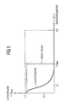
- Fig. 1 shows the relationship between the light intensity I and the radiation angle ⁇ of the laser light source.
- the maximum light intensity I max emitted by the laser light source is specified by the safety standards.
- the maximum usable radiation angle ⁇ max is determined by the optical components used, in particular by the acceptance angle of the glass fiber.
- a typical laser diode, for example a VCSEL laser diode has a relatively small radiation angle.
- 1 also shows the ideal profile for coupling emitted light into the multimode optical waveguide. This ideal course is determined by the maximum light intensity and the maximum usable radiation angle ⁇ max .
- an optical coupling arrangement for adapting the light source to the multimode optical waveguide is necessary.
- Multi-mode optical fibers can have a gradient index profile have or have a step-shaped index profile.
- the coupling is through Forming a lens on the face of the single-mode Optical fiber known. Due to the lenticular shape The face of the single-mode waveguide is used in the direct Coupling of the light emitted by the light source an increase in the proportion in the single-mode optical waveguide of the light coupled into the optical waveguide.
- Multi-mode optical fibers have been used to increase the optical Radiation angle of the injected light
- one Optical coupling arrangement proposed in which the light radiation source and the coupling face of the multimode Optical waveguide are arranged to each other in such a way that the coupled light rays against the geometric
- the axis of the optical waveguide is inclined at an angle.
- such an optical coupling arrangement only leads then an expansion of the radiation angle if it the multimode optical fiber is a waveguide deals with step index profile.
- short gradient index waveguides have the same properties as a GRIN lens (gradient index lens) on, i.e. through one towards the light rays inclined coupling face is the angle the radiation in the optical fiber changed, but only in one direction. Due to the imaging properties of the Gradient index optical fiber becomes the angle change retained during transmission through the optical fiber and then occurs according to the inclination or inclination of the Coupling face squinting. An expansion of the radiation angle does not take place.
- gradient index lens gradient index lens
- a Coupling glass fiber for optically coupling a light radiation source to a multi-mode optical fiber and a process to create its manufacture, in which a large proportion the light energy emitted by the laser light source is coupled into the optical fiber and at the same time the laser safety standards are met.
- Coupling glass fiber is the coupling face of the glass fiber core concavely curved inwards.
- the glass fiber core is preferably one Multimode fiber with a gradient index profile.
- the decoupling face of the fiber core is preferred planar.
- the concave coupling face is one preferred Embodiment rotationally symmetrical to the longitudinal axis of the fiberglass core.
- the concave coupling face rotationally symmetrical to an axis that is at an angle of inclination runs to the longitudinal axis of the glass fiber core.
- the angle of inclination is preferably 45 °.
- the coupling end face preferably has a mirror layer to reflect light.
- the light is coupled in at 90 ° Longitudinal axis of the glass fiber core possible.
- the invention also provides an optoelectronic light transmission component for multimode optical waveguides with at least one optical light radiation source for generating light and an associated coupling glass fiber for optically coupling the optical light radiation source to the multimode optical waveguide, wherein the coupling glass fiber has a glass fiber core with a coupling end face facing the light radiation source for coupling the generated light into the glass fiber core, and wherein the coupling end face of the glass fiber core is spherically curved inwards to expand the radiation angle of the coupled light.
- the coupling face is of the glass fiber core for radiation expansion of the coupled light concavely curved inwards.
- the optical light radiation source is preferably around a laser light source.
- the laser light source is preferably a laser diode.
- the laser diode a VCSEL laser diode.
- the glass fiber core has a diameter of 62.5 ⁇ m.
- the numerical aperture of the glass fiber core is preferably 0.275.
- the coupling face has a concave curvature with a medium one Radius of 0.3 mm.
- the invention also provides a method for producing a coupling glass fiber with the following steps, namely leveling both end faces of a raw glass fiber, which has a glass fiber core with a gradient index material profile and a glass fiber jacket surrounding the glass fiber core, Etching of at least one of the two end faces of the raw glass fiber with an etching liquid, the removal rate of which increases in accordance with the gradient index towards the center of the glass fiber core.
- the end face of the raw glass fiber is preferably used for etched a predetermined time.
- the process is the removal rate of the etching liquid for the Glass fiber cladding very low.
- the raw glass fiber is preferably in the etching liquid during the etching immersed.
- the etching liquid is preferably HF.
- the two end faces of the raw glass fiber are leveled in a preferred embodiment of the invention Manufacturing process by polishing.
- the removal rate of the etching liquid is one in particular preferred embodiment of the invention Process in the middle of the glass fiber core about 1.4 microns / min.
- the etching liquid preferably has a concentration of about 20%.
- Manufacturing process is at the center of the fiberglass core the end face is etched to an etching depth of 1-4 ⁇ m.
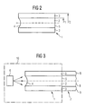
- Fig. 2 shows a first embodiment of the invention Coupling glass fiber 1 for optically coupling a light radiation source to a multimode optical fiber.
- the coupling glass fiber 1 has a glass fiber core 2 for transmitting light waves on.
- the glass fiber core 2 is one Glass fiber jacket 3 enclosed.
- the glass fiber core 2 has a coupling face 4 for coupling electromagnetic Waves or light. The light is from one Not shown light radiation source emitted and over the coupling end face 4 is coupled into the glass fiber core 2.
- the glass fiber core 2 also has a coupling end face 5 for extracting light from the glass fiber core into a multimode optical fiber.
- the coupling end face 4 of the glass fiber core 2 is used for Beam angle expansion of the coupled light.
- the Coupling face 4 is spherically curved inwards. In the preferred embodiment shown in FIG. 2 is the coupling face 4 essentially concavely curved inwards, the concave Coupling end face 4 rotationally symmetrical to the longitudinal axis of the glass fiber core 2.
- the glass fiber core 2 has a particularly preferred embodiment a diameter of 62.5 ⁇ m and has a numerical aperture of 0.275.
- the concave-shaped coupling face 4 has this particularly preferred embodiment is a medium one Radius of curvature of 0.3 mm. By the curvature of the coupling face 4 is the optimal coupling with the maximum possible illumination of the waveguide core is achieved. This enables the excitation of a higher number of modes.
- the concave-shaped coupling face 4 of the coupling glass fiber 1 leads to a change in the Radiation guidance in the waveguide without additional optical Components are necessary.
- Fig. 3 shows an arrangement in which the one shown in Fig. 2 first embodiment of the coupling glass fiber according to the invention for the optical coupling of a light radiation source 6 is used on a multimode optical waveguide 7.
- the Decoupling end face 5 of the glass fiber core 2 is located preferably planar to the multimode optical waveguide 7, of a glass fiber core 8 and one surrounding this fiber core Glass fiber jacket 9 has.
- the optical light radiation source 6 is a laser light source, usually is formed by a laser diode. At the light source 6 is preferably a VCSEL laser diode.
- the coupling glass fiber 1 and the optical light radiation source 6 are in an optoelectronic light transmission component 10 integrated.
- the coupling glass fiber 1 is used for optical Coupling the optical light radiation source 6 to the external Multi-mode optical waveguide 7. That of the light radiation source facing coupling face 4 of the glass fiber core 2 of the coupling glass fiber 1 is used to couple the light generated by the light radiation source 6.
- the Coupling optical fiber 1 ensures that the from the light radiation source 6 output power with a very high Efficiency in the multimode optical fiber 7 transmitted becomes.
- the coupling glass fiber 1 ensures that the laser security standards are met, i.e. the maximum permissible radiation power for all radiation angles is not exceeded.
- the essentially concave-shaped coupling face 4 arranged rotationally symmetrical to an axis N, that at an angle of inclination ⁇ to the longitudinal axis of the glass fiber core 2 runs.
- the angle of inclination ⁇ is at preferred embodiment 45 °.
- the coupling face 4 has a light-reflecting layer which is coupled of the light at an angle of 90 ° to the longitudinal axis the coupling glass fiber enables.
- Coupling glass fiber 1 enables an angular coupling of Light in the glass fiber core 2.
- the one shown in Fig. 4 Coupling glass fiber 1 to a 90 ° deflection of supplied Light can be used.
- the light hits in at an angle of 90 ° to the longitudinal axis of the glass fiber core 2 on the coupling face 4 of the glass fiber core, wherein the coupling face 4 like a concave one Mirror works and the incident light in the fiberglass core 2 reflected.
- the light to be deflected occurs from the light radiation source 6 generated light preferably by the Glass fiber jacket 3 through and meets the concave from the inside End face 4 of the glass fiber core 2.
- There will the light reflects and in the glass fiber core 2 to the decoupling end face 5 transferred.
- Fig. 5 shows the refractive index course within an inventive Coupling glass fiber 1.
- the glass fiber core 2 has a diameter of 2 x rl, which is preferably 62.5 microns.
- the refractive index or index within the Glass fiber core has a parabolic profile. there is the refractive index in the middle of the glass fiber core 2 am highest and falls parabolically to the edge of the glass fiber core 2 from.
- the glass fiber cladding 3 generally has a lower one Refractive index, which is essentially constant.
- the numerical aperture nA of the glass fiber core is one particularly preferred embodiment 0.275.
- nA sin ( ⁇ max ), where ⁇ max represents the maximum coupling angle when coupling light into the glass fiber core 2.
- a raw glass fiber is placed in a short carrier with a Inner bore inserted and on both sides of the bore shortened by breaking or cutting.
- the one shortened in this way Raw glass fiber stub has two end faces, which then be leveled.
- the raw glass fiber stub immersed in an etching liquid.
- the etching liquid it is, for example, HF hydrofluoric acid.
- the Immersion in the etching liquid takes place for a predetermined Time, wherein the etching liquid has a predetermined concentration of, for example, 20%.
- the removal rate the etching liquid is for the glass fiber core 2 and the glass fiber cladding 3 different.
- the etching liquid becomes like this chosen that the rate of removal of the etchant for the glass fiber cladding 3 significantly below the removal rate for the fiber core 2 lies. Because the fiber core 2 is a gradient index optical fiber with a parabolic refractive index curve has the chemical composition of the glass fiber core 2 also has a gradient. The etching liquid is chosen such that the rate of removal is Center of the glass fiber core 2 increases. The glass fiber core 2 has a higher germanium content at its center, for example on than on its edge.
- the removal rate of the etching liquid is in the center of the glass fiber core 2 about 1.4 microns / min.
- the coupling glass fiber 1 is in the etching liquid over a predetermined Time, with the glass fiber core 2 on the end face 4 preferably etched until the center of the fiber core etched to an etching depth of approximately 1 to 4 ⁇ m is.
- the etching depth in the middle of the glass fiber core is 2 in a particularly preferred embodiment 1.6 microns compared the planar face of the glass fiber cladding. This Etching depth of 1.6 ⁇ m corresponds to a concave curvature an average radius of 0.3 mm.
- the coupling glass fiber according to the invention 1 for an optoelectronic component 10 thus particularly easy to manufacture.
- the coupling glass fiber 1 according to the invention is in in a particularly simple manner in an optoelectronic light emitting component 10 can be installed.
- the adjustment and alignment of the Light radiation source 6 with respect to the invention Coupling glass fiber 1 is particularly simple because of the light radiation the light radiation source 6 in the longitudinal axis of the glass fiber core 2 runs. An adjustment of the light source with respect the coupling glass fiber 1 is therefore omitted.
Landscapes
- Physics & Mathematics (AREA)
- General Physics & Mathematics (AREA)
- Optics & Photonics (AREA)
- Optical Couplings Of Light Guides (AREA)
Abstract
Description
einer zugeordneten Koppelglasfaser zur optischen Kopplung der optischen Lichtstrahlungsquelle an den Mehrmoden-Lichtwellenleiter,
wobei die Koppelglasfaser einen Glasfaserkern mit einer der Lichtstrahlungsquelle zugewandten Einkopplungsstirnfläche zum Einkoppeln des erzeugten Lichtes in den Glasfaserkern aufweist,
und wobei die Einkopplungsstirnfläche des Glasfaserkerns zur Strahlungswinkelausweitung des eingekoppelten Lichtes sphärisch nach innen gekrümmt ist.
Ätzen von mindestens einer der beiden Stirnflächen der Rohglasfaser mit einer Ätzflüssigkeit, deren Abtragungsrate entsprechend dem Gradientenindex zur Mitte des Glasfaserkerns hin zunimmt.
wobei αmax den maximalen Einkoppelwinkel bei der Einkopplung von Licht in den Glasfaserkern 2 darstellt.
- 1
- Koppelglasfaser
- 2
- Glasfaserkern
- 3
- Glasfasermantel
- 4
- Einkoppelstirnfläche
- 5
- Auskoppelstirnfläche
- 6
- Lichtstrahlungsquelle
- 7
- Mehrmoden-Lichtwellenleiter
- 8
- Glasfaserkern des Mehrmoden-Lichtwellenleiters
- 9
- Glasfasermantel des Mehrmoden-Lichtwellenleiters
- 10
- Optoelektronisches Lichtsendebauelement
Claims (26)
- Koppelglasfaser zur optischen Kopplung einer Lichtstrahlungsquelle (6) an einen Mehrmoden-Lichtwellenleiter (7) mit:wobei die Einkopplungsstirnfläche (4) des Glasfaserkerns zur Strahlungswinkelausweitung des eingekoppelten Lichts konkavförmig nach innen gekrümmt ist.einem Glasfaserkern (2) zur Lichtwellenübertragung;einem den Glasfaserkern (2) umschließenden Glasfasermantel (3);einer Einkopplungsstirnfläche (4) des Glasfaserkerns (2) zum Einkoppeln von Licht, das von der Lichtstrahlungsquelle (6) emittiert wird, in den Glasfaserkern (2);einer Auskopplungsstirnfläche (5) des Glasfaserkerns (2) zum Auskoppeln von Licht aus dem Glasfaserkern (2) in den Mehrmoden-Lichtwellenleiter (7),
- Koppelglasfaser nach Anspruch 1,
dadurch gekennzeichnet, dass die Einkopplungsstirnfläche (4) spährisch nach innen gekrümmt ist. - Koppelglasfaser nach einem der vorangehenden Ansprüche,
dadurch gekennzeichnet, dass der Glasfaserkern (2) ein Mehrmoden-Lichtwellenleiter mit einem Gradientenindexprofil ist. - Koppelglasfaser nach einem der vorangehenden Ansprüche,
dadurch gekennzeichnet, dass die Auskopplungsstirnfläche (5) des Glasfaserkerns (2) planar ist. - Koppelglasfaser nach einem der vorangehenden Ansprüche,
dadurch gekennzeichnet, dass die konkavförmige Einkopplungsstirnfläche (4) rotationssymmetrisch zu der Längsachse des Glasfaserkerns (2) ist. - Koppelglasfaser nach einem der vorangehenden Ansprüche 1 bis 4,
dadurch gekennzeichnet, dass die konkavförmige Einkopplungsstirnfläche (4) rotationssymmetrisch zu einer Achse N ist, die in einem Neigungswinkel (γ) zu der Längsachse des Glasfaserkerns (2) verläuft. - Koppelglasfaser nach Anspruch 6,
dadurch gekennzeichnet, dass die Einkopplungsfläche (4) eine reflektierende Oberfläche und einen Neigungswinkel von 45° aufweist. - Optoelektronisches Lichtsendebauelement (10) für Mehrmoden-Lichtwellenleiter mit:mindestens einer optischen Lichtstrahlungsquelle (6) zur Erzeugung von Licht und einer zugeordneten Koppelglasfaser (1) zur optischen Kopplung der optischen Lichtstrahlungsquelle (6) an den Mehrmoden-Lichtwellenleiter (7),wobei die Koppelglasfaser (1) einen Glasfaserkern (2) mit einer der Lichtstrahlungsquelle (6) zugewandten Einkopplungsstirnfläche (4) zum Einkoppeln des erzeugten Lichts in den Glasfaserkern (2) aufweist,wobei die Einkopplungsstirnfläche (4) des Glasfaserkerns (2) zur Strahlungswinkelausweitung des eingekoppelten Lichts konkavförmig nach innen gekrümmt ist.
- Optoelektronisches Lichtsendebauelement nach Anspruch 8,
dadurch gekennzeichnet, dass die Einkopplungsstirnfläche (4) des Glasfaserkerns (2) sphärisch nach innen gekrümmt ist. - Optoelektronisches Lichtsendebauelement nach einem der vorangehenden Ansprüche 8 oder 9,
dadurch gekennzeichnet, dass die optische Lichtstrahlungsquelle (6) eine Laserlichtquelle ist. - Optoelektronisches Lichtsendebauelement Anspruch 10,
dadurch gekennzeichnet, dass die Laserlichtquelle eine Laserdiode ist. - Optoelektronisches Lichtsendebauelement nach Anspruch 11,
dadurch gekennzeichnet, dass die Laserdiode eine VCSEL-Laserdiode ist. - Optoelektronisches Lichtsendebauelement nach einem der vorangehenden Ansprüche,
dadurch gekennzeichnet, dass der Glasfaserkern (2) eine planare Auskopplungsstirnfläche (5) zum Auskoppeln des Lichtes in den Mehrmoden-Lichtwellenleiter (7) aufweist. - Optoelektronisches Lichtsendebauelement nach einem der vorangehenden Ansprüche,
dadurch gekennzeichnet, dass der Glasfaserkern (2) ein Mehrmoden-Lichtwellenleiter mit Gradientenindexprofil ist. - Optoelektronisches Lichtsendebauelement nach einem der
vorangehenden Ansprüche,
dadurch gekennzeichnet, dass der Glasfaserkern (2) einen Durchmesser von 62,5 µm aufweist. - Optoelektronisches Lichtsendebauelement nach einem der vorangehenden Ansprüche,
dadurch gekennzeichnet, dass die numerische Apertur des Glasfaserkerns 0,275 beträgt. - Optoelektronisches Lichtsendebauelement nach einem der vorangehenden Ansprüche,
dadurch gekennzeichnet, dass die Einkopplungsstirnfläche (4) eine konkavförmige Krümmung mit einem mittleren Radius von 0,3 mm aufweist. - Verfahren zur Herstellung einer Koppelglasfaser (1) mit den folgenden Schritten:(a) Planieren beider Stirnflächen einer Rohglasfaser, die einen Glasfaserkern (2) mit einem Gradientenindex-Materialprofil und einen den Glasfaserkern (2) umschließenden Glasfasermantel (3) aufweist;(b) Ätzen von mindestens einer der beiden Stirnflächen der Rohglasfaser in einer Ätzflüssigkeit, deren Abtragungsrate entsprechend dem Gradientenindex zur Mitte des Glasfaserkerns (2) hin zunimmt.
- Verfahren nach Anspruch 18, bei dem die Stirnfläche der Rohglasfaser für eine vorbestimmte Zeit geätzt wird.
- Verfahren nach einem der vorangehenden Ansprüche, bei dem die Abtragungsrate der Ätzflüssigkeit für den Glasfasermantel (3) niedrig ist.
- Verfahren nach einem der vorangehenden Ansprüche, bei dem die Rohglasfaser zum Ätzen in die Ätzflüssigkeit völlig eingetaucht wird.
- Verfahren nach einem der vorangehenden Ansprüche, bei dem die Ätzflüssigkeit Flußsäure HF ist.
- Verfahren nach einem der vorangehenden Ansprüche, bei dem das Planieren der Stirnflächen der Rohglasfaser durch Polieren erfolgt.
- Verfahren nach einem der vorangehenden Ansprüche, bei dem die Abtragungsrate der Ätzflüssigkeit in der Mitte des Glasfaserkerns (2) etwa 1,4 µm/min beträgt.
- Verfahren nach einem der vorangehenden Ansprüche, bei dem die Ätzflüssigkeit eine Säurekonzentration von etwa 20% aufweist.
- Verfahren nach einem der vorangehenden Ansprüche, bei dem die Mitte des Glasfaserkerns (2) an der Stirnfläche (4) bis zu einer Ätztiefe von 1 bis 4 µm geätzt wird.
Applications Claiming Priority (2)
| Application Number | Priority Date | Filing Date | Title |
|---|---|---|---|
| DE10033485 | 2000-07-10 | ||
| DE10033485A DE10033485C2 (de) | 2000-07-10 | 2000-07-10 | Koppelglasfaser zur optischen Kopplung einer Lichtstrahlungsquelle an einen Mehrmoden-Lichtwellenleiter, optoelektronisches Lichtsendebauelement für Mehrmoden-Lichtwellenleiter und Herstellungsverfahren für Koppelglasfenster |
Publications (2)
| Publication Number | Publication Date |
|---|---|
| EP1172674A2 true EP1172674A2 (de) | 2002-01-16 |
| EP1172674A3 EP1172674A3 (de) | 2002-06-19 |
Family
ID=7648421
Family Applications (1)
| Application Number | Title | Priority Date | Filing Date |
|---|---|---|---|
| EP01115518A Withdrawn EP1172674A3 (de) | 2000-07-10 | 2001-06-27 | Koppelglasfaser zur optischen Kopplung einer Lichtstrahlungsquelle an einem Mehrmoden-Lichtwellenleiter und Verfahren zu deren Herstellung |
Country Status (3)
| Country | Link |
|---|---|
| US (1) | US6529661B2 (de) |
| EP (1) | EP1172674A3 (de) |
| DE (1) | DE10033485C2 (de) |
Cited By (2)
| Publication number | Priority date | Publication date | Assignee | Title |
|---|---|---|---|---|
| FR2842966A1 (fr) * | 2002-07-26 | 2004-01-30 | France Telecom | Dispositif de raccordement entre une fibre optique et un emetteur optique |
| US8391727B2 (en) | 2008-12-19 | 2013-03-05 | U2T Photonics Ag | Detector module |
Families Citing this family (34)
| Publication number | Priority date | Publication date | Assignee | Title |
|---|---|---|---|---|
| US6738544B2 (en) * | 2002-06-11 | 2004-05-18 | Megladon Manufacturing Group | Thermally-shaped optical fiber and a method for forming the optical fiber |
| US6856728B2 (en) * | 2002-07-19 | 2005-02-15 | Multiplex, Inc. | Lensed fiber optic coupler |
| EP1558955A4 (de) * | 2002-10-15 | 2006-04-19 | Micron Optics Inc | Waferlose faser-fabry-perot-filter |
| WO2004059357A1 (en) | 2002-12-20 | 2004-07-15 | Micron Optics, Inc. | Temperature compensated ferrule holder for a fiber fabry-perot filter |
| CN100474010C (zh) * | 2003-07-18 | 2009-04-01 | 株式会社藤仓 | 渐变折射率多模光纤及其制造方法 |
| KR100522967B1 (ko) * | 2003-07-24 | 2005-10-19 | 삼성전자주식회사 | Gi pof의 둥근 끝처리를 통한 na 조절 방법 |
| US7324723B2 (en) * | 2003-10-06 | 2008-01-29 | Mitsui Chemicals, Inc. | Optical waveguide having specular surface formed by laser beam machining |
| US7347632B2 (en) * | 2003-12-12 | 2008-03-25 | Mina Farr | Optical connectors for electronic devices |
| US7548675B2 (en) * | 2004-09-29 | 2009-06-16 | Finisar Corporation | Optical cables for consumer electronics |
| US7706692B2 (en) * | 2004-09-29 | 2010-04-27 | Finisar Corporation | Consumer electronics with optical communication interface |
| WO2006076759A1 (en) * | 2005-01-21 | 2006-07-27 | Optiscan Pty Ltd | Fibre bundle for contact endomicroscopy |
| DE102005032593B4 (de) * | 2005-07-11 | 2007-07-26 | Technische Universität Berlin | Optisches Modul mit einer Leichtleitfaser und einem lichtemittierenden/lichtempfangenden Bauteil und Verfahren zum Herstellen |
| US7729618B2 (en) * | 2005-08-30 | 2010-06-01 | Finisar Corporation | Optical networks for consumer electronics |
| US7860398B2 (en) | 2005-09-15 | 2010-12-28 | Finisar Corporation | Laser drivers for closed path optical cables |
| KR100749528B1 (ko) | 2005-09-30 | 2007-08-16 | 주식회사 두산 | 광 접속 모듈 및 그 제조 방법 |
| US7778510B2 (en) | 2006-04-10 | 2010-08-17 | Finisar Corporation | Active optical cable electrical connector |
| US7712976B2 (en) * | 2006-04-10 | 2010-05-11 | Finisar Corporation | Active optical cable with integrated retiming |
| US8083417B2 (en) | 2006-04-10 | 2011-12-27 | Finisar Corporation | Active optical cable electrical adaptor |
| US7876989B2 (en) * | 2006-04-10 | 2011-01-25 | Finisar Corporation | Active optical cable with integrated power |
| US8769171B2 (en) * | 2007-04-06 | 2014-07-01 | Finisar Corporation | Electrical device with electrical interface that is compatible with integrated optical cable receptacle |
| US8244124B2 (en) | 2007-04-30 | 2012-08-14 | Finisar Corporation | Eye safety mechanism for use in optical cable with electrical interfaces |
| JP2010122614A (ja) * | 2008-11-21 | 2010-06-03 | Fuji Xerox Co Ltd | 光伝送装置及び光導波路 |
| KR101181446B1 (ko) * | 2008-11-28 | 2012-09-19 | 한국전자통신연구원 | 광도파로 및 양방향 광송수신 장치 |
| US9888837B2 (en) * | 2011-11-28 | 2018-02-13 | I-Tek Medical Solutions, Inc. | Fiber optic illumination device and method of manufacturing |
| WO2015061909A1 (en) * | 2013-11-01 | 2015-05-07 | UNIVERSITé LAVAL | Optical concentrator/diffuser using graded index waveguide |
| KR20180072285A (ko) | 2016-12-21 | 2018-06-29 | 주식회사 옵텔라 | 광결합장치 및 그 제조방법 |
| US10838556B2 (en) | 2019-04-05 | 2020-11-17 | Apple Inc. | Sensing system for detection of light incident to a light emitting layer of an electronic device display |
| US11611058B2 (en) | 2019-09-24 | 2023-03-21 | Apple Inc. | Devices and systems for under display image sensor |
| US11527582B1 (en) | 2019-09-24 | 2022-12-13 | Apple Inc. | Display stack with integrated photodetectors |
| US11592873B2 (en) | 2020-02-14 | 2023-02-28 | Apple Inc. | Display stack topologies for under-display optical transceivers |
| US11327237B2 (en) | 2020-06-18 | 2022-05-10 | Apple Inc. | Display-adjacent optical emission or reception using optical fibers |
| US11487859B2 (en) | 2020-07-31 | 2022-11-01 | Apple Inc. | Behind display polarized optical transceiver |
| US11839133B2 (en) | 2021-03-12 | 2023-12-05 | Apple Inc. | Organic photodetectors for in-cell optical sensing |
| US12124002B2 (en) | 2021-09-03 | 2024-10-22 | Apple Inc. | Beam deflector metasurface |
Family Cites Families (19)
| Publication number | Priority date | Publication date | Assignee | Title |
|---|---|---|---|---|
| GB1435523A (en) | 1972-07-12 | 1976-05-12 | Agency Ind Science Techn | Glass fibre optical waveguide |
| JPS5360651A (en) | 1976-11-12 | 1978-05-31 | Hitachi Ltd | Semiconductor laser with optical fibers |
| JPS54142988A (en) | 1978-04-28 | 1979-11-07 | Hitachi Ltd | Photo semiconductor device |
| US4510005A (en) * | 1982-09-28 | 1985-04-09 | Allied Corporation | Method and apparatus for reshaping and polishing an end face of an optical fiber |
| DE3685911T2 (de) * | 1985-04-19 | 1993-02-18 | Philips Nv | Herstellungsverfahren einer passiven faseroptischen komponente. |
| US4678902A (en) * | 1985-04-30 | 1987-07-07 | Metatech Corporation | Fiber optic transducers with improved sensitivity |
| US4986627A (en) * | 1988-06-10 | 1991-01-22 | Etat Francais (Centre National d'Etudes des Telecommunications) | Method for connecting optical fibres without Fresnel reflection and system thus detained, variable optical attenuator and system using this attenuator to measure the effect of the reflection coeficient on an optical line |
| US5101457A (en) | 1990-02-28 | 1992-03-31 | At&T Bell Laboratories | Optical fiber with an integral lens at its end portion |
| US5465314A (en) * | 1993-09-09 | 1995-11-07 | The Furukawa Electronic Co., Ltd. | Method of manufacturing optical connector |
| US5434940A (en) | 1994-03-24 | 1995-07-18 | The Whitaker Corporation | Active fiber needle |
| US5479543A (en) | 1994-06-02 | 1995-12-26 | Reliant Technologies, Inc. | Precision light-guiding terminal for optical fibers |
| US5751871A (en) * | 1996-01-05 | 1998-05-12 | Ceram Optec Industries, Inc. | Method for coupling of semiconductor lasers into optical fibers |
| US5659644A (en) * | 1996-06-07 | 1997-08-19 | Lucent Technologies Inc. | Fiber light source with multimode fiber coupler |
| US5825796A (en) * | 1996-09-25 | 1998-10-20 | Picolight Incorporated | Extended wavelength strained layer lasers having strain compensated layers |
| JP3039852B2 (ja) * | 1996-12-16 | 2000-05-08 | 住友電気工業株式会社 | 光ファイバコネクタ |
| EP0872747B1 (de) * | 1997-04-15 | 2002-09-18 | Sumitomo Electric Industries, Ltd. | Optisches Modul |
| US6137938A (en) * | 1997-06-04 | 2000-10-24 | Lasertron, Inc. | Flat top, double-angled, wedge-shaped fiber endface |
| US5985166A (en) * | 1997-10-29 | 1999-11-16 | California Institute Of Technology | Chemical etching of fiber probe |
| JPH11242129A (ja) * | 1998-02-26 | 1999-09-07 | Fujitsu Ltd | プラスチック光ファイバの加工方法及び接続方法 |
-
2000
- 2000-07-10 DE DE10033485A patent/DE10033485C2/de not_active Expired - Fee Related
-
2001
- 2001-06-25 US US09/891,149 patent/US6529661B2/en not_active Expired - Lifetime
- 2001-06-27 EP EP01115518A patent/EP1172674A3/de not_active Withdrawn
Cited By (2)
| Publication number | Priority date | Publication date | Assignee | Title |
|---|---|---|---|---|
| FR2842966A1 (fr) * | 2002-07-26 | 2004-01-30 | France Telecom | Dispositif de raccordement entre une fibre optique et un emetteur optique |
| US8391727B2 (en) | 2008-12-19 | 2013-03-05 | U2T Photonics Ag | Detector module |
Also Published As
| Publication number | Publication date |
|---|---|
| EP1172674A3 (de) | 2002-06-19 |
| DE10033485A1 (de) | 2002-01-31 |
| US20020076157A1 (en) | 2002-06-20 |
| US6529661B2 (en) | 2003-03-04 |
| DE10033485C2 (de) | 2003-10-23 |
Similar Documents
| Publication | Publication Date | Title |
|---|---|---|
| DE10033485C2 (de) | Koppelglasfaser zur optischen Kopplung einer Lichtstrahlungsquelle an einen Mehrmoden-Lichtwellenleiter, optoelektronisches Lichtsendebauelement für Mehrmoden-Lichtwellenleiter und Herstellungsverfahren für Koppelglasfenster | |
| RU2138892C1 (ru) | Оптическое волокно с двумя сердцевинами, способ его изготовления, волоконный лазер с двумя сердцевинами и волоконный усилитель с двумя сердцевинами | |
| DE68920270T2 (de) | Faseroptischer Stecker. | |
| DE10262414B3 (de) | Passiv modengekoppelter Faserlaser | |
| EP0191197A1 (de) | Monomode optische Übertragungsfaser, deren konisches Ende mit einer Linse versehen ist und Verfahren zu ihrer Herstellung | |
| US4193663A (en) | Coupling-equipped light guide | |
| AU725883B2 (en) | Flat top, double-angled, wedge-shaped fiber endface | |
| EP0114439A1 (de) | Monomode optische Übertragungsfaser mit konischem Endstück und Herstellungsverfahren für eine derartige Faser | |
| DE3912400C1 (de) | ||
| EP3407772B1 (de) | Beleuchtungseinrichtung | |
| DE69806300T2 (de) | Untereinheit und Verfahren zur Kopplung optischer Elemente | |
| DE19510559C1 (de) | Optische Sende- und Empfangsanordnung | |
| EP0155379B1 (de) | Koppelanordnung zum Ankoppeln eines Lichtwellenleiters an einen Halbleiterlaser und Verfahren zur Herstellung einer solchen Anordnung | |
| JPH0318805A (ja) | 光ファイバコネクタ | |
| DE112017002464B4 (de) | Optikmodul | |
| EP1770417A1 (de) | Optische Faser und Verfahren zu ihrer Herstellung | |
| DE2844129A1 (de) | Longitudinal gepumpter yag zu nd hoch 3+ -faserlaser | |
| WO2002103867A1 (de) | Opto-elektronisches lasermodul | |
| DE112004000194T5 (de) | Mit einer Linse versehene Faser mit einem kleinen Formfaktor und Verfahren zur Herstellung derselben | |
| DE102007045488B4 (de) | Seitengepumpter Laser | |
| DE10249839A1 (de) | Kupplungssystem für optische Fasern | |
| DE3733019A1 (de) | Koppelanordnung zum einkoppeln von licht einer halbleiterlaserdiode in eine multimode-glasfaser | |
| DE3207988A1 (de) | Verlustarme koppelanordnung fuer optische komponenten mit nur einer mikrolinse | |
| EP0045437B1 (de) | Ein- und Auskoppelvorrichtung zum Ein- und Auskoppeln von Lichtleistung in/aus einem optischen Wellenleiter, der aus Wellenleiterkern und -mantel besteht, und Verfahren zur Herstellung dieser Ein- und Auskoppelvorrichtung | |
| DE2625097A1 (de) | Verfahren zum ankoppeln von lichtleitern an halbleiterstrahler und nach diesem verfahren hergestellter lichtleiter |
Legal Events
| Date | Code | Title | Description |
|---|---|---|---|
| PUAI | Public reference made under article 153(3) epc to a published international application that has entered the european phase |
Free format text: ORIGINAL CODE: 0009012 |
|
| AK | Designated contracting states |
Kind code of ref document: A2 Designated state(s): AT BE CH CY DE DK ES FI FR GB GR IE IT LI LU MC NL PT SE TR |
|
| AX | Request for extension of the european patent |
Free format text: AL;LT;LV;MK;RO;SI |
|
| PUAL | Search report despatched |
Free format text: ORIGINAL CODE: 0009013 |
|
| AK | Designated contracting states |
Kind code of ref document: A3 Designated state(s): AT BE CH CY DE DK ES FI FR GB GR IE IT LI LU MC NL PT SE TR |
|
| AX | Request for extension of the european patent |
Free format text: AL;LT;LV;MK;RO;SI |
|
| AKX | Designation fees paid | ||
| REG | Reference to a national code |
Ref country code: DE Ref legal event code: 8566 |
|
| STAA | Information on the status of an ep patent application or granted ep patent |
Free format text: STATUS: THE APPLICATION IS DEEMED TO BE WITHDRAWN |
|
| 18D | Application deemed to be withdrawn |
Effective date: 20021220 |