EP1172620A1 - Anlage zur Luftdestillation und Stromherstellung und Verfahren dafür - Google Patents
Anlage zur Luftdestillation und Stromherstellung und Verfahren dafür Download PDFInfo
- Publication number
- EP1172620A1 EP1172620A1 EP01401844A EP01401844A EP1172620A1 EP 1172620 A1 EP1172620 A1 EP 1172620A1 EP 01401844 A EP01401844 A EP 01401844A EP 01401844 A EP01401844 A EP 01401844A EP 1172620 A1 EP1172620 A1 EP 1172620A1
- Authority
- EP
- European Patent Office
- Prior art keywords
- turbine
- nitrogen
- rich
- electricity
- fluid
- Prior art date
- Legal status (The legal status is an assumption and is not a legal conclusion. Google has not performed a legal analysis and makes no representation as to the accuracy of the status listed.)
- Withdrawn
Links
Images

Classifications
-
- F—MECHANICAL ENGINEERING; LIGHTING; HEATING; WEAPONS; BLASTING
- F25—REFRIGERATION OR COOLING; COMBINED HEATING AND REFRIGERATION SYSTEMS; HEAT PUMP SYSTEMS; MANUFACTURE OR STORAGE OF ICE; LIQUEFACTION SOLIDIFICATION OF GASES
- F25J—LIQUEFACTION, SOLIDIFICATION OR SEPARATION OF GASES OR GASEOUS OR LIQUEFIED GASEOUS MIXTURES BY PRESSURE AND COLD TREATMENT OR BY BRINGING THEM INTO THE SUPERCRITICAL STATE
- F25J3/00—Processes or apparatus for separating the constituents of gaseous or liquefied gaseous mixtures involving the use of liquefaction or solidification
- F25J3/02—Processes or apparatus for separating the constituents of gaseous or liquefied gaseous mixtures involving the use of liquefaction or solidification by rectification, i.e. by continuous interchange of heat and material between a vapour stream and a liquid stream
- F25J3/04—Processes or apparatus for separating the constituents of gaseous or liquefied gaseous mixtures involving the use of liquefaction or solidification by rectification, i.e. by continuous interchange of heat and material between a vapour stream and a liquid stream for air
- F25J3/04521—Coupling of the air fractionation unit to an air gas-consuming unit, so-called integrated processes
- F25J3/04593—The air gas consuming unit is also fed by an air stream
-
- F—MECHANICAL ENGINEERING; LIGHTING; HEATING; WEAPONS; BLASTING
- F25—REFRIGERATION OR COOLING; COMBINED HEATING AND REFRIGERATION SYSTEMS; HEAT PUMP SYSTEMS; MANUFACTURE OR STORAGE OF ICE; LIQUEFACTION SOLIDIFICATION OF GASES
- F25J—LIQUEFACTION, SOLIDIFICATION OR SEPARATION OF GASES OR GASEOUS OR LIQUEFIED GASEOUS MIXTURES BY PRESSURE AND COLD TREATMENT OR BY BRINGING THEM INTO THE SUPERCRITICAL STATE
- F25J3/00—Processes or apparatus for separating the constituents of gaseous or liquefied gaseous mixtures involving the use of liquefaction or solidification
- F25J3/02—Processes or apparatus for separating the constituents of gaseous or liquefied gaseous mixtures involving the use of liquefaction or solidification by rectification, i.e. by continuous interchange of heat and material between a vapour stream and a liquid stream
- F25J3/04—Processes or apparatus for separating the constituents of gaseous or liquefied gaseous mixtures involving the use of liquefaction or solidification by rectification, i.e. by continuous interchange of heat and material between a vapour stream and a liquid stream for air
- F25J3/04151—Purification and (pre-)cooling of the feed air; recuperative heat-exchange with product streams
- F25J3/04187—Cooling of the purified feed air by recuperative heat-exchange; Heat-exchange with product streams
- F25J3/0423—Subcooling of liquid process streams
-
- F—MECHANICAL ENGINEERING; LIGHTING; HEATING; WEAPONS; BLASTING
- F25—REFRIGERATION OR COOLING; COMBINED HEATING AND REFRIGERATION SYSTEMS; HEAT PUMP SYSTEMS; MANUFACTURE OR STORAGE OF ICE; LIQUEFACTION SOLIDIFICATION OF GASES
- F25J—LIQUEFACTION, SOLIDIFICATION OR SEPARATION OF GASES OR GASEOUS OR LIQUEFIED GASEOUS MIXTURES BY PRESSURE AND COLD TREATMENT OR BY BRINGING THEM INTO THE SUPERCRITICAL STATE
- F25J3/00—Processes or apparatus for separating the constituents of gaseous or liquefied gaseous mixtures involving the use of liquefaction or solidification
- F25J3/02—Processes or apparatus for separating the constituents of gaseous or liquefied gaseous mixtures involving the use of liquefaction or solidification by rectification, i.e. by continuous interchange of heat and material between a vapour stream and a liquid stream
- F25J3/04—Processes or apparatus for separating the constituents of gaseous or liquefied gaseous mixtures involving the use of liquefaction or solidification by rectification, i.e. by continuous interchange of heat and material between a vapour stream and a liquid stream for air
- F25J3/04248—Generation of cold for compensating heat leaks or liquid production, e.g. by Joule-Thompson expansion
- F25J3/04284—Generation of cold for compensating heat leaks or liquid production, e.g. by Joule-Thompson expansion using internal refrigeration by open-loop gas work expansion, e.g. of intermediate or oxygen enriched (waste-)streams
- F25J3/04309—Generation of cold for compensating heat leaks or liquid production, e.g. by Joule-Thompson expansion using internal refrigeration by open-loop gas work expansion, e.g. of intermediate or oxygen enriched (waste-)streams of nitrogen
- F25J3/04315—Lowest pressure or impure nitrogen, so-called waste nitrogen expansion
-
- F—MECHANICAL ENGINEERING; LIGHTING; HEATING; WEAPONS; BLASTING
- F25—REFRIGERATION OR COOLING; COMBINED HEATING AND REFRIGERATION SYSTEMS; HEAT PUMP SYSTEMS; MANUFACTURE OR STORAGE OF ICE; LIQUEFACTION SOLIDIFICATION OF GASES
- F25J—LIQUEFACTION, SOLIDIFICATION OR SEPARATION OF GASES OR GASEOUS OR LIQUEFIED GASEOUS MIXTURES BY PRESSURE AND COLD TREATMENT OR BY BRINGING THEM INTO THE SUPERCRITICAL STATE
- F25J3/00—Processes or apparatus for separating the constituents of gaseous or liquefied gaseous mixtures involving the use of liquefaction or solidification
- F25J3/02—Processes or apparatus for separating the constituents of gaseous or liquefied gaseous mixtures involving the use of liquefaction or solidification by rectification, i.e. by continuous interchange of heat and material between a vapour stream and a liquid stream
- F25J3/04—Processes or apparatus for separating the constituents of gaseous or liquefied gaseous mixtures involving the use of liquefaction or solidification by rectification, i.e. by continuous interchange of heat and material between a vapour stream and a liquid stream for air
- F25J3/04406—Processes or apparatus for separating the constituents of gaseous or liquefied gaseous mixtures involving the use of liquefaction or solidification by rectification, i.e. by continuous interchange of heat and material between a vapour stream and a liquid stream for air using a dual pressure main column system
- F25J3/04412—Processes or apparatus for separating the constituents of gaseous or liquefied gaseous mixtures involving the use of liquefaction or solidification by rectification, i.e. by continuous interchange of heat and material between a vapour stream and a liquid stream for air using a dual pressure main column system in a classical double column flowsheet, i.e. with thermal coupling by a main reboiler-condenser in the bottom of low pressure respectively top of high pressure column
-
- F—MECHANICAL ENGINEERING; LIGHTING; HEATING; WEAPONS; BLASTING
- F25—REFRIGERATION OR COOLING; COMBINED HEATING AND REFRIGERATION SYSTEMS; HEAT PUMP SYSTEMS; MANUFACTURE OR STORAGE OF ICE; LIQUEFACTION SOLIDIFICATION OF GASES
- F25J—LIQUEFACTION, SOLIDIFICATION OR SEPARATION OF GASES OR GASEOUS OR LIQUEFIED GASEOUS MIXTURES BY PRESSURE AND COLD TREATMENT OR BY BRINGING THEM INTO THE SUPERCRITICAL STATE
- F25J3/00—Processes or apparatus for separating the constituents of gaseous or liquefied gaseous mixtures involving the use of liquefaction or solidification
- F25J3/02—Processes or apparatus for separating the constituents of gaseous or liquefied gaseous mixtures involving the use of liquefaction or solidification by rectification, i.e. by continuous interchange of heat and material between a vapour stream and a liquid stream
- F25J3/04—Processes or apparatus for separating the constituents of gaseous or liquefied gaseous mixtures involving the use of liquefaction or solidification by rectification, i.e. by continuous interchange of heat and material between a vapour stream and a liquid stream for air
- F25J3/04521—Coupling of the air fractionation unit to an air gas-consuming unit, so-called integrated processes
- F25J3/04563—Integration with a nitrogen consuming unit, e.g. for purging, inerting, cooling or heating
- F25J3/04575—Integration with a nitrogen consuming unit, e.g. for purging, inerting, cooling or heating for a gas expansion plant, e.g. dilution of the combustion gas in a gas turbine
-
- F—MECHANICAL ENGINEERING; LIGHTING; HEATING; WEAPONS; BLASTING
- F25—REFRIGERATION OR COOLING; COMBINED HEATING AND REFRIGERATION SYSTEMS; HEAT PUMP SYSTEMS; MANUFACTURE OR STORAGE OF ICE; LIQUEFACTION SOLIDIFICATION OF GASES
- F25J—LIQUEFACTION, SOLIDIFICATION OR SEPARATION OF GASES OR GASEOUS OR LIQUEFIED GASEOUS MIXTURES BY PRESSURE AND COLD TREATMENT OR BY BRINGING THEM INTO THE SUPERCRITICAL STATE
- F25J2200/00—Processes or apparatus using separation by rectification
- F25J2200/20—Processes or apparatus using separation by rectification in an elevated pressure multiple column system wherein the lowest pressure column is at a pressure well above the minimum pressure needed to overcome pressure drop to reject the products to atmosphere
-
- F—MECHANICAL ENGINEERING; LIGHTING; HEATING; WEAPONS; BLASTING
- F25—REFRIGERATION OR COOLING; COMBINED HEATING AND REFRIGERATION SYSTEMS; HEAT PUMP SYSTEMS; MANUFACTURE OR STORAGE OF ICE; LIQUEFACTION SOLIDIFICATION OF GASES
- F25J—LIQUEFACTION, SOLIDIFICATION OR SEPARATION OF GASES OR GASEOUS OR LIQUEFIED GASEOUS MIXTURES BY PRESSURE AND COLD TREATMENT OR BY BRINGING THEM INTO THE SUPERCRITICAL STATE
- F25J2240/00—Processes or apparatus involving steps for expanding of process streams
- F25J2240/80—Hot exhaust gas turbine combustion engine
-
- F—MECHANICAL ENGINEERING; LIGHTING; HEATING; WEAPONS; BLASTING
- F25—REFRIGERATION OR COOLING; COMBINED HEATING AND REFRIGERATION SYSTEMS; HEAT PUMP SYSTEMS; MANUFACTURE OR STORAGE OF ICE; LIQUEFACTION SOLIDIFICATION OF GASES
- F25J—LIQUEFACTION, SOLIDIFICATION OR SEPARATION OF GASES OR GASEOUS OR LIQUEFIED GASEOUS MIXTURES BY PRESSURE AND COLD TREATMENT OR BY BRINGING THEM INTO THE SUPERCRITICAL STATE
- F25J2280/00—Control of the process or apparatus
- F25J2280/02—Control in general, load changes, different modes ("runs"), measurements
-
- F—MECHANICAL ENGINEERING; LIGHTING; HEATING; WEAPONS; BLASTING
- F25—REFRIGERATION OR COOLING; COMBINED HEATING AND REFRIGERATION SYSTEMS; HEAT PUMP SYSTEMS; MANUFACTURE OR STORAGE OF ICE; LIQUEFACTION SOLIDIFICATION OF GASES
- F25J—LIQUEFACTION, SOLIDIFICATION OR SEPARATION OF GASES OR GASEOUS OR LIQUEFIED GASEOUS MIXTURES BY PRESSURE AND COLD TREATMENT OR BY BRINGING THEM INTO THE SUPERCRITICAL STATE
- F25J2290/00—Other details not covered by groups F25J2200/00 - F25J2280/00
- F25J2290/62—Details of storing a fluid in a tank
Definitions
- the present invention relates to an air distillation installation and for producing electricity, of the type comprising on the one hand a air distillation, having at least one outlet for a fluid rich in nitrogen and an output of a product to be supplied in the liquid state, and on the other hand a unit to gas turbine comprising a combustion chamber and a turbine production of electricity whose inlet is connected to an outlet of the combustion chamber, the installation further comprising means for expansion of a nitrogen-rich fluid to produce cooling energy making it possible to supply said liquid product, the air distillation apparatus being connected in parallel to these expansion means and to the turbine inlet supply of electricity to supply them with at least one fluid rich in nitrogen.
- the gas turbine unit participates for example in supplying a electrical distribution network.
- the air distillation apparatus supplies products from the air distillation, typically a fluid rich in nitrogen and a fluid rich in oxygen. At least one of these products is usually supplied as is liquid, which facilitates its storage.
- the maximum instantaneous electrical power that a gas turbine unit is generally limited by the characteristics of the compressor that such a unit usually comprises upstream of its combustion chamber.
- An object of the invention is to solve this problem by providing a installation of the aforementioned type allowing easy adaptation to variations electricity needs of consumers on a distribution supplied by this installation.
- the invention relates to an installation of the aforementioned type, characterized in that it comprises means for adjusting the flow rates of the flow of nitrogen-rich fluid sent respectively to the means of expansion and towards the electricity production turbine, and means of determination of the electrical power to be produced with the turbine electricity production.
- the invention further relates to a production process of electricity and air distillation using an installation as defined above, characterized in that the flow rate of the fluid flow is increased rich in nitrogen supplying the power generation turbine when the electrical power to be produced increases.
- the flow rate of the fluid stream rich in nitrogen feeding the electricity generating turbine when the power decrease in electrical output is reduced.
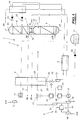
- FIG. 1 represents an installation 1 for distilling air and supply of electricity which includes an air distillation unit 2 and a gas turbine unit 3.
- the air to be distilled, previously compressed by the compressor 11 and purified by device 12, is cooled by the main exchange line thermal 8 to the vicinity of its dew point and then introduced into the tank of the medium pressure column 5.
- the vaporizer-condenser 7 vaporizes liquid oxygen, of purity generally greater than 90% and typically 99.5%, of the tank of the low pressure column 6 by nitrogen condensation 7 at the head of the column medium pressure 5.
- LP “poor liquid” (almost pure nitrogen), taken at the top of the medium pressure column 5, is sub-cooled on passing through the exchanger auxiliary thermal 10, then expanded in an expansion valve 23 and finally injected at the top of the low pressure column 6.
- Impure or “residual” NR nitrogen withdrawn from the top of the low pressure column 6 via an outlet 25, is heated on passing through the auxiliary heat exchanger 10 then returned to a series of passages 26 of the main heat exchange line 8.
- the residual nitrogen passes through these passages 26 causing the cooling of the air to be distilled.
- This residual nitrogen is divided, within passages 26, in two streams, the first of which crosses passages 26 over their entire length then is sent to the gas turbine unit 3 by a line 27, as described below.
- the second flow only crosses an upstream part of the passages 26 then is sent via an intermediate output 28 and a pipe 29 to the turbine 13.
- This second stream of residual nitrogen is expanded there, and therefore cooled, then passes through the auxiliary heat exchanger 9 while heating up before being sent back to the main heat exchange line 8 for participate again in the cooling of the air to be distilled in a series of separate passages from passages 26.
- Gaseous oxygen taken from the bottom of the low pressure column 6 via an outlet 30, is heated when crossing the main line heat exchange 8 and distributed by a production line 31.
- Liquid oxygen is drawn from the bottom column tank pressure 6 via an outlet 32 then sent to the heat exchanger auxiliary 9 where it is sub-cooled by the second stream of residual nitrogen. This liquid oxygen is then expanded in an expansion valve 33, up to a pressure slightly higher than atmospheric pressure, before feeding the tank 14.
- Air is compressed by compressor 16 and then sent to the chamber combustion 17 in which a pressurized fuel such as natural gas is introduced via a pipe 35.
- the gases from combustion in chamber 17 are sent towards the intake of the turbine 18 where they relax by driving the compressor 16 and the alternator 19.
- the alternator 19 supplies, for example an electrical distribution network.
- the first stream of residual nitrogen flowing in line 27 is compressed in compressor 21, to substantially reach the pressure gases from chamber 17, then sent to the turbine inlet 18 to relax there with the gases from the combustion chamber 17.
- the outlet 25 of residual nitrogen from the low pressure column 6 is therefore connected in parallel to the turbine 18, downstream of the combustion 17, and to the turbine 13.
- the residual nitrogen can allow to increase the power supplied by the gas turbine unit 3, increasing the flow circulating in the turbine 18, but also to supply liquid oxygen, thanks to its expansion in the turbine 13 which produces the cooling energy necessary.
- the electronic control unit 43 typically comprises a microprocessor suitably programmed to regulate the nitrogen flow rates waste circulating in lines 27 and 29 as described below.
- Unit 43 compares the values provided by the means of determination 40 and 44. When the electrical power to be supplied is greater than that supplied by the alternator 19, that is to say when the electrical requirements of the network supplied by the alternator 19 increase, the control unit 43 then controls the valves 41 and 42 to increase the flow rate of the first waste nitrogen flow and decrease the flow rate of the second waste nitrogen flow.
- the flow of expanded gases in the turbine 18 increases and the alternator 19 can provide the additional electrical power requested.
- the the maximum electrical power that can be supplied is therefore not limited by the characteristics of the compressor 16 but by those of the turbine 18.
- the flow rate of the second stream of residual nitrogen having decreased, unit 2 air distillation supplies less liquid oxygen. It is not a problem, even if the liquid oxygen demand of consumers increases, since it is possible to use all of the liquid oxygen stored in the tank 14 to satisfy their demand.
- the adjustment valve 42 can be, if necessary, completely closed, the assembly residual nitrogen is then sent to the gas turbine unit 3.
- the cold behavior of the distillation column 4 is ensured by example by returning liquid oxygen from tank 14 to the line main heat exchange 8 or by any other means such as a turbine blowing the air to be distilled in the low pressure column.
- control unit 43 controls increasing the flow of the second flow and decreasing the flow of the first stream.
- the adjustment valve 41 can be completely closed, all of the residual nitrogen is then sent to the turbine 13 so to supply the reservoir 14 with liquid oxygen.
- FIG. 1 makes it possible to easily adapt the electric power supplied by the gas turbine unit 3 to the needs in electricity without being limited by the characteristics of the compressor 16.
- the structure of the gas turbine unit 3 can be different, the combustion chamber 17 being able to be supplied by oxidizing under pressure, such as air, by various means.
- the first stream of residual nitrogen can also be heated before to be sent to turbine 18.
- the above principles are not limited to one unit 2 comprising a double distillation column. So any type of air distillation, having an air inlet and fluid outlets rich in nitrogen and rich in oxygen, can be used. The or a rich fluid outlet in nitrogen is then connected in parallel to turbines 13 and 18.
- Valves 41 and 42 can be integrated respectively in the compressor 21 and turbine 23, for example in the form of blades directors.
- the second stream of residual nitrogen can be relaxed by various means to allow the production of a product in the liquid state, such as oxygen, nitrogen or even argon. It is not not necessary that this second relaxed flow and the product to be supplied to the state liquids pass through the same heat exchanger.
- the second flow of nitrogen after its expansion in the turbine 13 is sent directly to the heat exchange line 8, the auxiliary heat exchanger 9 and the expansion valve 33 having been removed.
- the liquid oxygen is then stored, except for the pressure drops, at the low pressure column operating pressure which can be significantly higher than atmospheric pressure.
- the turbine 18 can be a turbine of which an upstream stage is mechanically connected by a first shaft compressor 16 to drive it, and a downstream stage is connected mechanically by a separate second shaft to the alternator 19 for the result.
- the residual nitrogen from exit 25 can be split into two streams upstream of the auxiliary heat exchanger 10 and therefore upstream from the main line heat exchange 8.
- the first flow is then compressed and then reheated on crossing the main heat exchange line 8 and finally supplies the turbine 18.
- the second flow passes through the auxiliary heat exchanger 10, then the part upstream of the passages 26 of the main heat exchange line 8. Then, the second flow follows the path of the embodiment of FIG. 1.
- the turbines 13 and 18 can be connected to two separate nitrogen-rich fluid outlets.
- the turbine 13 can be connected to the outlet 25 as shown in Figure 1, while part of the lean liquid LP is sent to a pump, then in the main heat exchange line 8 before to supply the turbine 18.
Applications Claiming Priority (2)
| Application Number | Priority Date | Filing Date | Title |
|---|---|---|---|
| FR0009100 | 2000-07-12 | ||
| FR0009100A FR2811712B1 (fr) | 2000-07-12 | 2000-07-12 | Installation de distillation d'air et de production d'electricite et procede correspondant |
Publications (1)
| Publication Number | Publication Date |
|---|---|
| EP1172620A1 true EP1172620A1 (de) | 2002-01-16 |
Family
ID=8852392
Family Applications (1)
| Application Number | Title | Priority Date | Filing Date |
|---|---|---|---|
| EP01401844A Withdrawn EP1172620A1 (de) | 2000-07-12 | 2001-07-10 | Anlage zur Luftdestillation und Stromherstellung und Verfahren dafür |
Country Status (4)
| Country | Link |
|---|---|
| US (1) | US6539701B2 (de) |
| EP (1) | EP1172620A1 (de) |
| CA (1) | CA2353020A1 (de) |
| FR (1) | FR2811712B1 (de) |
Families Citing this family (1)
| Publication number | Priority date | Publication date | Assignee | Title |
|---|---|---|---|---|
| FR2828729B1 (fr) * | 2001-08-14 | 2003-10-31 | Air Liquide | Installation de production d'oxygene sous haute pression par distillation d'air |
Citations (5)
| Publication number | Priority date | Publication date | Assignee | Title |
|---|---|---|---|---|
| DE3908505A1 (de) * | 1988-03-15 | 1989-09-28 | Voest Alpine Ind Anlagen | Verfahren zur gewinnung von fluessig-roheisen in einem einschmelzvergaser |
| EP0357299A1 (de) * | 1988-08-31 | 1990-03-07 | The BOC Group plc | Lufttrennung |
| EP0519688A1 (de) * | 1991-06-20 | 1992-12-23 | Air Products And Chemicals, Inc. | Verfahren und System zur Reglung einer kryogenen Lufttrennungseinheit bei schnellen Produktionsänderungen |
| US5410869A (en) * | 1993-01-18 | 1995-05-02 | Abb Management Ag | Method of operating a combination power plant by coal or oil gasification |
| US5666825A (en) * | 1993-04-29 | 1997-09-16 | L'air Liquide, Societe Anonyme Pour L'etude Et L'exploitation Des Procedes Georges Claude | Process and installation for the separation of air |
Family Cites Families (7)
| Publication number | Priority date | Publication date | Assignee | Title |
|---|---|---|---|---|
| FR779601A (fr) * | 1934-07-30 | 1935-04-10 | Signalisateur électrique lumineux de direction à éclairage intermittent et particulièrement adapté pour véhicules automobiles | |
| US4178763A (en) * | 1978-03-24 | 1979-12-18 | Westinghouse Electric Corp. | System for minimizing valve throttling losses in a steam turbine power plant |
| GB2080929B (en) * | 1980-07-22 | 1984-02-08 | Air Prod & Chem | Producing gaseous oxygen |
| US5081845A (en) | 1990-07-02 | 1992-01-21 | Air Products And Chemicals, Inc. | Integrated air separation plant - integrated gasification combined cycle power generator |
| US5060480A (en) * | 1990-10-30 | 1991-10-29 | L'air Liquide, Societe Anonyme Pour L'etude Et L'exploitation Des Procedes Georges Claude | Process and apparatus for the liquefaction of a flow of gaseous oxygen |
| US6393821B1 (en) * | 1998-08-21 | 2002-05-28 | Edan Prabhu | Method for collection and use of low-level methane emissions |
| US6281601B1 (en) * | 1999-07-23 | 2001-08-28 | Capstone Turbine Corporation | Turbogenerator power control system and method |
-
2000
- 2000-07-12 FR FR0009100A patent/FR2811712B1/fr not_active Expired - Fee Related
-
2001
- 2001-07-10 EP EP01401844A patent/EP1172620A1/de not_active Withdrawn
- 2001-07-10 CA CA002353020A patent/CA2353020A1/en not_active Abandoned
- 2001-07-12 US US09/902,609 patent/US6539701B2/en not_active Expired - Lifetime
Patent Citations (5)
| Publication number | Priority date | Publication date | Assignee | Title |
|---|---|---|---|---|
| DE3908505A1 (de) * | 1988-03-15 | 1989-09-28 | Voest Alpine Ind Anlagen | Verfahren zur gewinnung von fluessig-roheisen in einem einschmelzvergaser |
| EP0357299A1 (de) * | 1988-08-31 | 1990-03-07 | The BOC Group plc | Lufttrennung |
| EP0519688A1 (de) * | 1991-06-20 | 1992-12-23 | Air Products And Chemicals, Inc. | Verfahren und System zur Reglung einer kryogenen Lufttrennungseinheit bei schnellen Produktionsänderungen |
| US5410869A (en) * | 1993-01-18 | 1995-05-02 | Abb Management Ag | Method of operating a combination power plant by coal or oil gasification |
| US5666825A (en) * | 1993-04-29 | 1997-09-16 | L'air Liquide, Societe Anonyme Pour L'etude Et L'exploitation Des Procedes Georges Claude | Process and installation for the separation of air |
Also Published As
| Publication number | Publication date |
|---|---|
| FR2811712B1 (fr) | 2002-09-27 |
| US20020020165A1 (en) | 2002-02-21 |
| US6539701B2 (en) | 2003-04-01 |
| FR2811712A1 (fr) | 2002-01-18 |
| CA2353020A1 (en) | 2002-01-12 |
Similar Documents
| Publication | Publication Date | Title |
|---|---|---|
| EP0940624B1 (de) | Station und Verfahren zur Verteilung von Gas | |
| EP0628778B1 (de) | Verfahren und Hochdruckgasversorgungseinheit für eine ein Luftbestandteil verbrauchende Anlage | |
| EP0178207B1 (de) | Verfahren und Anlage zur kryogenischen Fraktionierung gasförmiger Massen | |
| EP1223395B2 (de) | Integriertes Verfahren zur Luftzerlegung und Energieerzeugung | |
| EP1447634B1 (de) | Verfahren und Vorrichtung zur Erzeugung von mindestens einem gasförmigen unter hohem Druck stehenden Produktstrom, wie Sauerstoff, Stickstoff oder Argon, durch Tieftemperaturzerlegung von Luft | |
| EP3839392A1 (de) | Verfahren zur verflüssigung von erdgas und zur rückgewinnung möglicher flüssiger fraktionen von erdgas, das zwei halboffene erdgas-kühlkreisläufe und einen geschlossenen kühlkreislauf mit kühlmittelgas umfasst | |
| FR2837783A1 (fr) | Installation pour la fourniture de combustible gazeux a un ensemble de production energetique d'un navire de transport de gaz liquefie | |
| EP1672269A1 (de) | Anordnung zum Fördern von gasförmigem Brennstoff zu einer Energieerzeugungseinheit eines Schiffes zum Transport von Flüssiggas | |
| FR2819583A1 (fr) | Procede integre de separation d'air et de generation d'energie et installation pour la mise en oeuvre d'un tel procede | |
| FR2690711A1 (fr) | Procédé de mise en Óoeuvre d'un groupe turbine à gaz et ensemble combiné de production d'énergie et d'au moins un gaz de l'air. | |
| WO2014128408A2 (fr) | Station d'abaissement de pression d'un gaz et de liquéfaction du gaz | |
| EP3764047B1 (de) | Verfahren und anlage zur herstellung von flüssigem wasserstoff | |
| FR2723184A1 (fr) | Procede et installation de production d'oxygene gazeux sous pression a debit variable | |
| EP1102953B1 (de) | Anlage zur erzeugung von niederspannugsstrom mit einer anlage, die in einer luftzerlegungsanlage integriert ist | |
| EP0952415A1 (de) | Rektifikationsverfahren und -vorrichtung zur variablen Argon Herstellung | |
| CA2557287C (fr) | Procede de renovation d'une installation combinee d'un haut-fourneau et d'une unite de separation de gaz de l'air | |
| EP1172620A1 (de) | Anlage zur Luftdestillation und Stromherstellung und Verfahren dafür | |
| EP0932005A1 (de) | Komibinierte Ofen und Lufttrennungsanlage und Verfahren zur Anwendung | |
| EP0932006A1 (de) | Komibinierte Ofen und Lufttrennungsanlage und Verfahren zur Anwendung | |
| EP1651915B1 (de) | Verfahren und system zur versorgung einer lufttrenneinheit mittels einer gasturbine | |
| EP1219910A1 (de) | Verfahren zur Luftzuführung für zu mindestens eine Gasturbinenanlage und zu mindestens eine Luftzerlegungsanlage, und Anlage zur Ausführung des Verfahrens | |
| FR2706595A1 (fr) | Procédé et installation de production d'oxygène et/ou d'azote sous pression à débit variable. | |
| EP1409937B1 (de) | Verfahren zur dampferzeugung und luftzerlegung | |
| EP1697690A2 (de) | Verfahren und anlage zur anreicherung eines gasstroms mit einer seiner komponenten | |
| FR2827186A1 (fr) | Procede et installation de distillation d'air et de production de vapeur d'eau |
Legal Events
| Date | Code | Title | Description |
|---|---|---|---|
| PUAI | Public reference made under article 153(3) epc to a published international application that has entered the european phase |
Free format text: ORIGINAL CODE: 0009012 |
|
| AK | Designated contracting states |
Kind code of ref document: A1 Designated state(s): AT BE CH CY DE DK ES FI FR GB GR IE IT LI LU MC NL PT SE TR |
|
| AX | Request for extension of the european patent |
Free format text: AL;LT;LV;MK;RO;SI |
|
| RAP1 | Party data changed (applicant data changed or rights of an application transferred) |
Owner name: L'AIR LIQUIDE, S.A. A DIRECTOIRE ET CONSEIL DE SUR |
|
| 17P | Request for examination filed |
Effective date: 20020716 |
|
| AKX | Designation fees paid |
Free format text: AT BE CH CY DE DK ES FI FR GB GR IE IT LI LU MC NL PT SE TR |
|
| 17Q | First examination report despatched |
Effective date: 20040528 |
|
| STAA | Information on the status of an ep patent application or granted ep patent |
Free format text: STATUS: THE APPLICATION IS DEEMED TO BE WITHDRAWN |
|
| 18D | Application deemed to be withdrawn |
Effective date: 20041008 |