EP1172493A1 - A wall element - Google Patents
A wall element Download PDFInfo
- Publication number
- EP1172493A1 EP1172493A1 EP00850128A EP00850128A EP1172493A1 EP 1172493 A1 EP1172493 A1 EP 1172493A1 EP 00850128 A EP00850128 A EP 00850128A EP 00850128 A EP00850128 A EP 00850128A EP 1172493 A1 EP1172493 A1 EP 1172493A1
- Authority
- EP
- European Patent Office
- Prior art keywords
- wall element
- elongated
- building
- strengthening member
- wall
- Prior art date
- Legal status (The legal status is an assumption and is not a legal conclusion. Google has not performed a legal analysis and makes no representation as to the accuracy of the status listed.)
- Granted
Links
- 238000005728 strengthening Methods 0.000 claims abstract description 41
- 230000003014 reinforcing effect Effects 0.000 claims description 20
- 238000003466 welding Methods 0.000 claims description 8
- 229910000831 Steel Inorganic materials 0.000 claims description 6
- 239000010959 steel Substances 0.000 claims description 6
- XLYOFNOQVPJJNP-UHFFFAOYSA-N water Substances O XLYOFNOQVPJJNP-UHFFFAOYSA-N 0.000 claims description 5
- 239000002699 waste material Substances 0.000 claims description 4
- 230000004308 accommodation Effects 0.000 claims description 2
- 238000007599 discharging Methods 0.000 claims description 2
- 238000000034 method Methods 0.000 description 5
- 238000010276 construction Methods 0.000 description 4
- 239000000945 filler Substances 0.000 description 3
- 230000005611 electricity Effects 0.000 description 2
- 238000004519 manufacturing process Methods 0.000 description 2
- 230000002787 reinforcement Effects 0.000 description 2
- 150000001875 compounds Chemical class 0.000 description 1
- 230000003247 decreasing effect Effects 0.000 description 1
- 238000010438 heat treatment Methods 0.000 description 1
- 238000007689 inspection Methods 0.000 description 1
- 238000000465 moulding Methods 0.000 description 1
- 229920001084 poly(chloroprene) Polymers 0.000 description 1
- 238000007789 sealing Methods 0.000 description 1
- 238000009423 ventilation Methods 0.000 description 1
Images

Classifications
-
- E—FIXED CONSTRUCTIONS
- E04—BUILDING
- E04B—GENERAL BUILDING CONSTRUCTIONS; WALLS, e.g. PARTITIONS; ROOFS; FLOORS; CEILINGS; INSULATION OR OTHER PROTECTION OF BUILDINGS
- E04B1/00—Constructions in general; Structures which are not restricted either to walls, e.g. partitions, or floors or ceilings or roofs
- E04B1/02—Structures consisting primarily of load-supporting, block-shaped, or slab-shaped elements
- E04B1/04—Structures consisting primarily of load-supporting, block-shaped, or slab-shaped elements the elements consisting of concrete, e.g. reinforced concrete, or other stone-like material
Definitions
- the present invention relates to an exterior concrete wall element according to the preamble of claim 1.
- a plurality of reinforcing band devices and constructions for junctions between wall elements of buildings are well known. Generally the constructions are used to secure building elements to each other. In areas where earthquakes frequently appears, buildings can be reinforced by means of, for example, strips.
- the floor components, i.e. floor slabs, of a building can be uncovered at their ends, so that service and inspection work can be done in an efficient manner. That is, when the wall elements not cover the ends of the floor slabs, hollow cores and their outlet placed in the floor slabs, will be easy to reach.
- wall elements comprising means for reinforcing and for holding a plurality of walls to each other.
- This wall elements can be load-bearing walls in a building with service lines, such as electric cables, water pipes, waste pipes an the like, extending into and out of rooms and enclosed areas in the building, which service lines further are placed in or adjacent exterior walls in a manner to be accessible from outside the building.
- service lines such as electric cables, water pipes, waste pipes an the like
- an intention of the inventor is to provide a wall element, which has an integrated multi-purpose reinforcing device. This will make the construction of a building more uncomplicated and therefore more flexible and cost effective.
- an exterior concrete wall element as initially defined, which is characterized in that at least one elongated strengthening member is provided adjacent to said support surface, parallel to the prolongation of said upper side, and which member comprises connection means for connecting said member to a similar elongated strengthening member provided at an adjoining wall element.
- the wall elements can be reinforced within the area of the junction between the wall elements and the floor components. That is, the wall element can be fixed in a position in relation to an adjoining wall element, by that the member counteract eventual forces in the direction of the prolongation of the upper side. This will provide that a building with the wall elements according to the invention will resist the forces of an earthquake in a better way than common wall elements do.
- the elongated strengthening member extends with an essentially lesser height above the upper side than the height of at least one hollow core outlet discharging at the transverse outer end for making said outlet accessible from outside a building comprising said wall element, which hollow core, for accommodation of electric cables, water pipes, waste pipes and the like, is provided in the floor component.
- the hollow cores can be accessible from outside the building, and the building is more resistant to earth quakes etc.
- the elongated strengthening member is mounted to said wall element, wherein the width and the length of the support surface are determined by respectively the member and the intersection line between the support surface and the plane of the back side.
- the floor component can be mounted to the upper side of the wall elements in an easy way, since the support surface is physical already before the floor component will be placed thereto. This will make the assembly work more cost effective.
- the strengthening member will prevent the wall elements and the floor components to move in a direction transverse to the prolongation of the member in a plane parallel to the floor components.
- a gusset plate respectively is mounted at each corner of the wall element each gusset plate having a first flange essentially in the same plane as the plane of the upper and lower side and a second flange recessed in the front side, wherein the elongated strengthening member is mountable to the first flanges.
- the elongated strengthening member can be mounted to the upper side of the wall element.
- the second flange is provided for a plate connectable to another wall element.
- the elongated strengthening member is made of a hollow square steel tube.
- the area, on which weld joints and reinforcing bars etc. are placed, will be larger than what a homogeneous steel bar would provide with the same strength.
- the cross-section of the strengthening member can be rectangular as well.
- an elongated junction bar is mountable to the elongated strengthening member constituting its connection means.
- each strengthening member of each wall element can be connected to each other and the members can together constitute a strip around a building.
- a reinforcing strip is connectable to said elongated junction bar, which strip extends to an other exterior concrete wall element placed at the opposite side of a building and between two elongated concrete floor components.
- the wall elements according to the invention are in a fixed position, standing in an opposite position of a building in a direction corresponding to the prolongation of the floor component.
- plates are mountable to the second flanges of the wall element for making a junction between the wall element and second flanges of adjoining wall elements.
- the storeys of a multi-storied building with hollow cores accommodating hollow cores, accessible from outside the building can be reinforced. That is, the area within the lower side of a wall element can be fixed towards the strengthening member of the wall element standing adjoining below this element. At the same time, corners of other adjoining wall elements of the same type can be connected to the strengthening member.
- the joint between the strengthening member and the first flange will according to the invention by means of the plate be additionally more rigid.
- the outer side of the plate will, since the second flange is recessed in the front side of the wall element, have the same plane as the front side. This will simplify the assembling work with panels covering the building sides.
- the wall elements constitute exterior walls in a multi-storied building, wherein the elongated strengthening members are mounted to the wall element.
- a building owns a flexibility in mounting and a cost effective status concerning the assembly work.
- This multi-storied building has also an integrated reinforcing device, which makes a building according to the invention resistant to earth quakes etc.
- the elongated strengthening members is mounted to the gusset plates, the reinforcing bar and the elongated junction bar by means of welding.
- a strong junction is provided between the members, plates and bars and which art of connection provides a flexibility in the assembly work.
- At least one reinforcing bar is connectable to the elongated strengthening member and to the hollow core outlet for making a junction between said wall element and said floor component. This will prevent the wall element to move in a direction into the building comprising the wall elements according to the invention.
- the exterior concrete wall element according to the invention is adapted to be a building element in a multi-purpose system, wherein a continuous reinforcing strip is provided by means of the plurality of the elongated strengthening members connected to each other and placed in a building according to the invention.
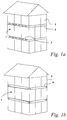
- Fig. 1a shows schematically a building 1.
- Wall components 3, known in prior art, and floor slabs, also in this application called elongated floor components 5, are according to known technique used for the building 1.
- the building 1 has hollow cores 7 accessible from the outside of the building 1.
- panel elements (not shown) can be mounted onto the wall components 3 of the building 1.
- the hollow cores 7 provide that each flat, office or the like can be supplied individually with electricity, cold water etc, which enables each flat to be responsible for its own heating, electricity and ventilation etc.
- Fig. 1b shows the building 1 with strips 9 around it.
- This reinforcing device is common for buildings built in earthquake areas. But the strips 9 are covering the hollow cores 7 and there is a problem for service personal to carry out their service work. They have to bore holes (not shown) through the strips 9 to reach the hollow cores 7. This is expensive and weakens the reinforcement.
- Fig. 2 shows schematically in perspective a section of a junction between four exterior concrete wall elements 11 according to the invention and two floor components 5.
- the exterior concrete wall element 11 comprises a first and a second vertical side 13, 14. It further comprises a front and a back side 15, 16 and an upper side 17 and a lower side 18.
- the upper and lower sides 17, 18 have each a support surface 20 for supporting the elongated concrete floor component 5 at its outer ends 19.
- the floor component 5 comprises hollow cores 7 according to known technique.
- the hollow cores 7 extend through the floor component 5.
- the hollow cores 7 accommodate electric cables 21, water pipes, waste pipes and the like. Outlets 23 discharge at the outer end of the floor component 5 and inlets 24 are provided inside the building.
- the electric cable 21 is accessible from the outside of the building by means of the invention. Since an elongated strengthening member 25 is provided adjacent, to the support surface 20, parallel to the prolongation of the upper side 17, (that is on the upper side 17 of the wall element 11) and this member 25 is connected via a connection means 26 (such as an elongated junction bar 27, se also fig. 3) to a similar elongated strengthening member 25', the wall elements can not be moved from each other sideways. The fastening of the member 25 at the wall element 11 will be described more closely further on with reference to the fig. 3 and 4a-4b.
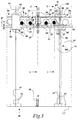
- Fig. 3 illustrates the exterior concrete wall element 11 in a front view.
- the elongated strengthening member 25 extends with an essentially lesser height h above the upper side 17 than the height H of the hollow core outlet 23.
- the hollow cores 7 accommodate electrical cables 21.
- the member 25 is mounted to the wall element 11 in a way to define or determine a support surface 20 (see fig. 2) at the upper side 17.
- the length of this support surface 20 corresponds to the length of the wall element 11 and the width of the support surface 20 corresponds to the distance between the intersection line between the support surface 20 and a plane of said backside 16.
- An L-formed reinforcing bar 29 is connected by means of welding to the strengthening member 25 and to one of the hollow cores 7 of the floor component 5.
- This hollow core 7 is plugged with a plug 31 (se fig. 4a) and refilled with concrete filler 33.
- a hair pin formed bar 35 connected to a holding loop 36 of the above placed wall is also moulded into this plugged hollow core 7 for reinforcement.
- a lifting loop 37 moulded into the same plugged line 23. This provides a junction between the wall element 11 and the floor component 5.
- the lifting loop 37 is though provided for lifting the wall element and for reinforcing the junction between floor component 5 and the wall element 11.
- a gusset plate 39 is mounted respectively at each corner of the wall element 11, each gusset plate 39 having a first flange 41 and a second flange 43.
- the first flange 41 is arranged in the same plane as the upper side 17.
- the elongated strengthening member 25, made of a hollow square steel tube bear on the upper side 17 when welded to the first flanges 41.
- the second flange is arranged in a recess 49 of the front side 15 (this is clearly shown in fig. 4b) so that a plate 45, which will be described further on with reference to fig. 4b, will have its outer side in line with the front side 15.
- To the right in fig. 3 a further plate has not yet been mounted.
- the plate is mounted by means of welding to the second flanges 43 of the wall elements 11, 11'.
- junction bar 27 is mounted by means of welding to the top side of the strengthening member 25 arranged at the upper side 17.
- the junction bar 27 further is welded to the strengthening member 25' of the adjoining wall element 11'. In this way a connection means 26 between two wall elements 11, 11' is provided.
- neoprene plates 55 placed between the lower side 18 of a above standing wall element 11 and the floor component 5 for making a distance between the wall element 11 and the floor component 5 and for decreasing the impact sound.
- Sealing compound 56 (see fig. 4) is filled in the space between the lower sides 18 of the wall elements 11 and the floor components 5. Joints between the wall elements 11 and 11' have the reference 47.
- a reinforcing strip 29' is connectable to said elongated junction bar 27, which strip 29' extends to an other exterior concrete wall element (not shown) placed at the opposite side of a building (not shown) and between two elongated concrete floor components 5, 5'.
- the ends of the reinforcing strip 29' is welded to the junction bar 27 of respectively wall opposite wall element 11. This means that a fixture has been provided also in the direction of the floor components 5. As seen in the fig. 3 the strip 29' is placed between the floor components
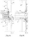
- fig. 4a which shows a cross-sectional view along line A-A in fig. 3, is illustrated how the strengthening member 25, in this embodiment a hollow square steel tube, is connected to the floor component 5 by means of the L-formed reinforcing bar 29 made of steel.
- One part of the bar 29 is projecting into the outlet 23 of one of the hollow cores 7.
- a plug 31 is mounted in the hollow core 7 and a section of an upper side of the floor component 5 is removed for moulding the filler 33 into the space formed by the outlet 23.
- the hair pin bar 35 and the lifting loop 37 is also projecting into the hollow core 7 surrounded by the filler 33.
- the holding loop 36 as well as the lifting loop 37 are moulded into the wall element 11 during the production of the wall element 11.
- Fig. 4b illustrates a cross-section along line B-B in fig. 3.
- the gusset plates 39 are mounted in the recess 49 of the front side 15.
- the gusset plates 39 are fastened to the wall elements 11, 11' by means of into the wall element 11 extending pins 51 and the fastening can be done during the manufacturing of the wall element 11.
- Weld joints 52 are also illustrated in the figures 4a and 4b.
- the recess 49 permits the plate 45 (not shown in fig. 4b, but in fig. 3) to have its outer side in line with the front side 15 of the wall element 11. This will simplify the mounting of a panel (not shown) outside the building, since an even surface thus is achieved.
- the electric cable 21 or the like is supported by means of a support 53.
- the element gusset plate may in this application be called welding plate as well.
- Vertical bars 100 is moulded in the wall element 11 and are connectable by means of welding to a similar wall element standing above the element 11 via the gusset plate 39. In this way a cross-like connection is provided near the corners of each wall element 11 and strengthening members are though provided in a building also in a vertical direction.
- elongated strengthening member 25 is mounted at the lower side 18 of the wall element 11 or at both sides are possible embodiments wherein the member 25 could be a strip or a homogenous band.
- the outlet 23 will be accessible from outside the building by means of the invention, and a flexibility according to the purpose of the inventor of this invention is achieved.
- the wall elements 11 according to the invention may constitute exterior walls in a multi-storied building, which wall elements comprises the elongated strengthening members, the floor components according to known technique may be used. Of course may other floor components be used as well within the framework of the invention. Other ways of fastening the members, bars and elements than welding are also possible in the framework of this invention.
Landscapes
- Engineering & Computer Science (AREA)
- Architecture (AREA)
- Physics & Mathematics (AREA)
- Electromagnetism (AREA)
- Civil Engineering (AREA)
- Structural Engineering (AREA)
- Building Environments (AREA)
- Bidet-Like Cleaning Device And Other Flush Toilet Accessories (AREA)
- Finishing Walls (AREA)
Abstract
Description
- The present invention relates to an exterior concrete wall element according to the preamble of
claim 1. - A plurality of reinforcing band devices and constructions for junctions between wall elements of buildings are well known. Generally the constructions are used to secure building elements to each other. In areas where earthquakes frequently appears, buildings can be reinforced by means of, for example, strips.
- Sometimes it is an advantage if the floor components, i.e. floor slabs, of a building can be uncovered at their ends, so that service and inspection work can be done in an efficient manner. That is, when the wall elements not cover the ends of the floor slabs, hollow cores and their outlet placed in the floor slabs, will be easy to reach.
- A major problem today is that known reinforcing band devices cover the section of a building, that is the area where the ends of the floor slabs are placed between two on each other standing wall elements. This means that no service lines can be placed in the floor slabs being accessible from outside the building, since the band will cover the outlets. If there is a wish to place service lines in the floor slabs, accessible from the outside the building, the building worker must bore holes in the band for reaching the hollow cores. This will cause high costs and a complexity even during the service work and also a poorer strength of the building.
- There is a need for wall elements comprising means for reinforcing and for holding a plurality of walls to each other. This wall elements can be load-bearing walls in a building with service lines, such as electric cables, water pipes, waste pipes an the like, extending into and out of rooms and enclosed areas in the building, which service lines further are placed in or adjacent exterior walls in a manner to be accessible from outside the building. The present invention is a result of a development work concerning the invention described in the EP 0 225 419 A1.
- There is a need for a simple means for alignment of wall elements during the construction process.
- There is also a need for a wall element with a reinforcing device, which is easy to mount and which is cost effective.
- Further on, an intention of the inventor is to provide a wall element, which has an integrated multi-purpose reinforcing device. This will make the construction of a building more uncomplicated and therefore more flexible and cost effective.
- This has been solved by an exterior concrete wall element as initially defined, which is characterized in that at least one elongated strengthening member is provided adjacent to said support surface, parallel to the prolongation of said upper side, and which member comprises connection means for connecting said member to a similar elongated strengthening member provided at an adjoining wall element.
- Hereby the wall elements can be reinforced within the area of the junction between the wall elements and the floor components. That is, the wall element can be fixed in a position in relation to an adjoining wall element, by that the member counteract eventual forces in the direction of the prolongation of the upper side. This will provide that a building with the wall elements according to the invention will resist the forces of an earthquake in a better way than common wall elements do.
- Preferably, the elongated strengthening member extends with an essentially lesser height above the upper side than the height of at least one hollow core outlet discharging at the transverse outer end for making said outlet accessible from outside a building comprising said wall element, which hollow core, for accommodation of electric cables, water pipes, waste pipes and the like, is provided in the floor component. In this way, wherein hollow cores provided in the floor components according to known technique and wherein the wall elements not are covering the transverse outer ends of the floor components, the hollow cores can be accessible from outside the building, and the building is more resistant to earth quakes etc.
- Suitably, the elongated strengthening member is mounted to said wall element, wherein the width and the length of the support surface are determined by respectively the member and the intersection line between the support surface and the plane of the back side. Hereby the floor component can be mounted to the upper side of the wall elements in an easy way, since the support surface is physical already before the floor component will be placed thereto. This will make the assembly work more cost effective. Furthermore, the strengthening member will prevent the wall elements and the floor components to move in a direction transverse to the prolongation of the member in a plane parallel to the floor components.
- Suitably, a gusset plate respectively is mounted at each corner of the wall element each gusset plate having a first flange essentially in the same plane as the plane of the upper and lower side and a second flange recessed in the front side, wherein the elongated strengthening member is mountable to the first flanges. Hereby the elongated strengthening member can be mounted to the upper side of the wall element. The second flange is provided for a plate connectable to another wall element.
- Preferably, the elongated strengthening member is made of a hollow square steel tube. In this way the area, on which weld joints and reinforcing bars etc. are placed, will be larger than what a homogeneous steel bar would provide with the same strength. Of course, the cross-section of the strengthening member can be rectangular as well.
- Suitably, an elongated junction bar is mountable to the elongated strengthening member constituting its connection means. Hereby respectively each strengthening member of each wall element can be connected to each other and the members can together constitute a strip around a building.
- Suitably, a reinforcing strip is connectable to said elongated junction bar, which strip extends to an other exterior concrete wall element placed at the opposite side of a building and between two elongated concrete floor components. Hereby the wall elements according to the invention are in a fixed position, standing in an opposite position of a building in a direction corresponding to the prolongation of the floor component.
- Preferably, plates are mountable to the second flanges of the wall element for making a junction between the wall element and second flanges of adjoining wall elements. Hereby the storeys of a multi-storied building with hollow cores accommodating hollow cores, accessible from outside the building, can be reinforced. That is, the area within the lower side of a wall element can be fixed towards the strengthening member of the wall element standing adjoining below this element. At the same time, corners of other adjoining wall elements of the same type can be connected to the strengthening member. Also, the joint between the strengthening member and the first flange will according to the invention by means of the plate be additionally more rigid. The outer side of the plate will, since the second flange is recessed in the front side of the wall element, have the same plane as the front side. This will simplify the assembling work with panels covering the building sides.
- Suitably, the wall elements constitute exterior walls in a multi-storied building, wherein the elongated strengthening members are mounted to the wall element. In such way a building owns a flexibility in mounting and a cost effective status concerning the assembly work. This multi-storied building has also an integrated reinforcing device, which makes a building according to the invention resistant to earth quakes etc.
- Preferably, the elongated strengthening members is mounted to the gusset plates, the reinforcing bar and the elongated junction bar by means of welding. Hereby a strong junction is provided between the members, plates and bars and which art of connection provides a flexibility in the assembly work.
- Preferably, at least one reinforcing bar is connectable to the elongated strengthening member and to the hollow core outlet for making a junction between said wall element and said floor component. This will prevent the wall element to move in a direction into the building comprising the wall elements according to the invention.
- The exterior concrete wall element according to the invention, is adapted to be a building element in a multi-purpose system, wherein a continuous reinforcing strip is provided by means of the plurality of the elongated strengthening members connected to each other and placed in a building according to the invention.
- The invention will now be described schematically with reference to the accompanying drawings, in which
- Fig. 1a-1b schematically illustrates in perspective a building with wall elements according to prior art,
- Fig. 2 schematically illustrates in perspective a section of a junction between a wall element according to the invention and a floor component,
- Fig. 3 schematically illustrates a wall element according to the invention in a front view from outside, and
- Fig. 4a-4b schematically illustrate respectively cross-sectional views taken along lines A-A and B-B in fig. 3.
-
- Fig. 1a shows schematically a
building 1.Wall components 3, known in prior art, and floor slabs, also in this application calledelongated floor components 5, are according to known technique used for thebuilding 1. Thebuilding 1 hashollow cores 7 accessible from the outside of thebuilding 1. Of course, panel elements (not shown) can be mounted onto thewall components 3 of thebuilding 1. Thehollow cores 7 provide that each flat, office or the like can be supplied individually with electricity, cold water etc, which enables each flat to be responsible for its own heating, electricity and ventilation etc. - Fig. 1b shows the
building 1 withstrips 9 around it. This reinforcing device is common for buildings built in earthquake areas. But thestrips 9 are covering thehollow cores 7 and there is a problem for service personal to carry out their service work. They have to bore holes (not shown) through thestrips 9 to reach thehollow cores 7. This is expensive and weakens the reinforcement. - Fig. 2 shows schematically in perspective a section of a junction between four exterior
concrete wall elements 11 according to the invention and twofloor components 5. The exteriorconcrete wall element 11 comprises a first and a secondvertical side back side upper side 17 and alower side 18. The upper andlower sides support surface 20 for supporting the elongatedconcrete floor component 5 at its outer ends 19. Thefloor component 5 compriseshollow cores 7 according to known technique. Thehollow cores 7 extend through thefloor component 5. - The
hollow cores 7 accommodateelectric cables 21, water pipes, waste pipes and the like.Outlets 23 discharge at the outer end of thefloor component 5 andinlets 24 are provided inside the building. Theelectric cable 21 is accessible from the outside of the building by means of the invention. Since an elongated strengtheningmember 25 is provided adjacent, to thesupport surface 20, parallel to the prolongation of theupper side 17, (that is on theupper side 17 of the wall element 11) and thismember 25 is connected via a connection means 26 (such as anelongated junction bar 27, se also fig. 3) to a similar elongated strengthening member 25', the wall elements can not be moved from each other sideways. The fastening of themember 25 at thewall element 11 will be described more closely further on with reference to the fig. 3 and 4a-4b. - Fig. 3 illustrates the exterior
concrete wall element 11 in a front view. The elongated strengtheningmember 25 extends with an essentially lesser height h above theupper side 17 than the height H of thehollow core outlet 23. Thehollow cores 7 accommodateelectrical cables 21. Themember 25 is mounted to thewall element 11 in a way to define or determine a support surface 20 (see fig. 2) at theupper side 17. The length of thissupport surface 20 corresponds to the length of thewall element 11 and the width of thesupport surface 20 corresponds to the distance between the intersection line between thesupport surface 20 and a plane of saidbackside 16. - An L-formed reinforcing
bar 29 is connected by means of welding to the strengtheningmember 25 and to one of thehollow cores 7 of thefloor component 5. Thishollow core 7 is plugged with a plug 31 (se fig. 4a) and refilled withconcrete filler 33. A hair pin formedbar 35 connected to a holdingloop 36 of the above placed wall is also moulded into this pluggedhollow core 7 for reinforcement. Further on, extending from theupper side 17 of thewall element 11 is a liftingloop 37 moulded into the same pluggedline 23. This provides a junction between thewall element 11 and thefloor component 5. The liftingloop 37 is though provided for lifting the wall element and for reinforcing the junction betweenfloor component 5 and thewall element 11. - A
gusset plate 39 is mounted respectively at each corner of thewall element 11, eachgusset plate 39 having afirst flange 41 and asecond flange 43. Thefirst flange 41 is arranged in the same plane as theupper side 17. In this way the elongated strengtheningmember 25, made of a hollow square steel tube, bear on theupper side 17 when welded to thefirst flanges 41. The second flange is arranged in arecess 49 of the front side 15 (this is clearly shown in fig. 4b) so that aplate 45, which will be described further on with reference to fig. 4b, will have its outer side in line with thefront side 15. To the left in fig. 3 theplate 45 is mounted. To the right in fig. 3 a further plate has not yet been mounted. The plate is mounted by means of welding to thesecond flanges 43 of thewall elements 11, 11'. - An
elongated junction bar 27 is mounted by means of welding to the top side of the strengtheningmember 25 arranged at theupper side 17. Thejunction bar 27 further is welded to the strengthening member 25' of the adjoining wall element 11'. In this way a connection means 26 between twowall elements 11, 11' is provided. - Between the
lower side 18 of a abovestanding wall element 11 and thefloor component 5 areneoprene plates 55 placed for making a distance between thewall element 11 and thefloor component 5 and for decreasing the impact sound. Sealing compound 56 (see fig. 4) is filled in the space between thelower sides 18 of thewall elements 11 and thefloor components 5. Joints between thewall elements 11 and 11' have thereference 47. - A reinforcing strip 29' is connectable to said
elongated junction bar 27, which strip 29' extends to an other exterior concrete wall element (not shown) placed at the opposite side of a building (not shown) and between two elongatedconcrete floor components 5, 5'. The ends of the reinforcing strip 29' is welded to thejunction bar 27 of respectively wall oppositewall element 11. This means that a fixture has been provided also in the direction of thefloor components 5. As seen in the fig. 3 the strip 29' is placed between the floor components - In fig. 4a, which shows a cross-sectional view along line A-A in fig. 3, is illustrated how the strengthening
member 25, in this embodiment a hollow square steel tube, is connected to thefloor component 5 by means of the L-formed reinforcingbar 29 made of steel. One part of thebar 29 is projecting into theoutlet 23 of one of thehollow cores 7. Aplug 31 is mounted in thehollow core 7 and a section of an upper side of thefloor component 5 is removed for moulding thefiller 33 into the space formed by theoutlet 23. Thehair pin bar 35 and the liftingloop 37 is also projecting into thehollow core 7 surrounded by thefiller 33. The holdingloop 36 as well as the liftingloop 37 are moulded into thewall element 11 during the production of thewall element 11. - Fig. 4b illustrates a cross-section along line B-B in fig. 3. The
gusset plates 39 are mounted in therecess 49 of thefront side 15. Thegusset plates 39 are fastened to thewall elements 11, 11' by means of into thewall element 11 extendingpins 51 and the fastening can be done during the manufacturing of thewall element 11. Weld joints 52 are also illustrated in the figures 4a and 4b. Therecess 49 permits the plate 45 (not shown in fig. 4b, but in fig. 3) to have its outer side in line with thefront side 15 of thewall element 11. This will simplify the mounting of a panel (not shown) outside the building, since an even surface thus is achieved. Theelectric cable 21 or the like is supported by means of asupport 53. The element gusset plate may in this application be called welding plate as well. -
Vertical bars 100 is moulded in thewall element 11 and are connectable by means of welding to a similar wall element standing above theelement 11 via thegusset plate 39. In this way a cross-like connection is provided near the corners of eachwall element 11 and strengthening members are though provided in a building also in a vertical direction. - Other embodiments, such as wherein the elongated strengthening
member 25 is mounted at thelower side 18 of thewall element 11 or at both sides are possible embodiments wherein themember 25 could be a strip or a homogenous band. - The
outlet 23 will be accessible from outside the building by means of the invention, and a flexibility according to the purpose of the inventor of this invention is achieved. Since thewall elements 11 according to the invention may constitute exterior walls in a multi-storied building, which wall elements comprises the elongated strengthening members, the floor components according to known technique may be used. Of course may other floor components be used as well within the framework of the invention. Other ways of fastening the members, bars and elements than welding are also possible in the framework of this invention.
Claims (11)
- An exterior concrete wall element (11) comprising a first and a second vertical side surface (13, 14), a front and a back side (15, 16), an upper and a lower side (17, 18) each having a support surface (20) for supporting at least one elongated concrete floor component (5) at its transverse outer end (19), characterized in that at least one elongated strengthening member (25) is provided adjacent to said support surface (20), parallel to the prolongation of said upper side (17), and which member (25) comprises connection means (26) for connecting said member (25) to a similar elongated strengthening member (25') provided at an adjoining wall element (11').
- A wall element (11) according to claim 1, characterized in that said elongated strengthening member (25) extends with an essentially lesser height (h) above said upper side (17) than the height (H) of at least one hollow core (7) with an outlet (23) discharging at said transverse outer end (19) for making said outlet (23) accessible from outside a building comprising said wall element (11), which hollow core (7), for accommodation of electric cables (21), water pipes, waste pipes and the like, is provided in said floor component (5).
- A wall element (11) according to claim 1 or 2, characterized in that said elongated strengthening member (25) is mounted to said wall element (11), wherein the width and the length of said support surface (20) are determined by respectively said member (25) and the intersection line between said support surface (20) and the plane of said back side (16).
- A wall element (11) according to any one of the preceding claims, characterized in that a gusset plate (39) respectively is mounted at each corner of said wall element (11), each gusset plate (39) having a first flange (41) essentially in the same plane as the plane of said upper and lower side (17, 18) and a second flange (43) recessed in said front side (15), wherein said elongated strengthening member (25) is mountable to said first flanges (41).
- A wall element (11) according to any one of the preceding claims, characterized in that said elongated strengthening member (25) is made of a hollow square steel tube.
- A wall element (11) according to any one of the preceding claims, characterized in that an elongated junction bar (27) is mountable to said elongated strengthening member (25) constituting its connections means (26).
- A wall element (11) according to any one of the preceding claims, characterized in that a reinforcing strip (29') is connectable to said elongated junction bar (27), which strip (29') extends to an other exterior concrete wall element placed at the opposite side of a building and between two elongated concrete floor components (5).
- A wall element (11) according to any one of the preceding claims, characterized in that plates (45) are mountable to said second flanges (43) of said wall element (11) for making a junction between said wall element (11) and second flanges (43) of adjoining wall elements (11').
- A wall element (11) according to claims 1-3, characterized in that at least one reinforcing bar (29) is connectable to the elongated strengthening member (25) and to said hollow core outlet (23) for making a junction between said wall element (11) and said floor component (5).
- A wall element (11) according to any one of the preceding claims, characterized in that said wall elements (11) constitute exterior walls in a multi-storied building, wherein said elongated strengthening members (25) are mounted to said wall element.
- A wall element (11) according to any one of the preceding claims, characterized in that said elongated strengthening members (25) is mounted to said gusset plates (39), said reinforcing bar (29) and said elongated junction bar (27) by means of welding.
Priority Applications (3)
| Application Number | Priority Date | Filing Date | Title |
|---|---|---|---|
| AT00850128T ATE299209T1 (en) | 2000-07-14 | 2000-07-14 | WALL ELEMENT |
| DE60021182T DE60021182D1 (en) | 2000-07-14 | 2000-07-14 | wall element |
| EP00850128A EP1172493B1 (en) | 2000-07-14 | 2000-07-14 | A wall element |
Applications Claiming Priority (1)
| Application Number | Priority Date | Filing Date | Title |
|---|---|---|---|
| EP00850128A EP1172493B1 (en) | 2000-07-14 | 2000-07-14 | A wall element |
Publications (2)
| Publication Number | Publication Date |
|---|---|
| EP1172493A1 true EP1172493A1 (en) | 2002-01-16 |
| EP1172493B1 EP1172493B1 (en) | 2005-07-06 |
Family
ID=8175672
Family Applications (1)
| Application Number | Title | Priority Date | Filing Date |
|---|---|---|---|
| EP00850128A Expired - Lifetime EP1172493B1 (en) | 2000-07-14 | 2000-07-14 | A wall element |
Country Status (3)
| Country | Link |
|---|---|
| EP (1) | EP1172493B1 (en) |
| AT (1) | ATE299209T1 (en) |
| DE (1) | DE60021182D1 (en) |
Citations (5)
| Publication number | Priority date | Publication date | Assignee | Title |
|---|---|---|---|---|
| US2883852A (en) * | 1956-03-26 | 1959-04-28 | Harry W Midby | Masonry building construction |
| US3330084A (en) * | 1965-04-12 | 1967-07-11 | Lockheed Aircraft Corp | Wall panel joint cap construction |
| DE2158475A1 (en) * | 1971-11-25 | 1973-05-30 | Stetter Baumaschf Georg | PRE-FABRICATION SYSTEM WITH PRODUCTION PROCESS |
| US3736709A (en) * | 1971-07-13 | 1973-06-05 | Techcrete Inc | Building system |
| EP0225419A1 (en) | 1985-12-09 | 1987-06-16 | Skarne System AB | A building |
-
2000
- 2000-07-14 EP EP00850128A patent/EP1172493B1/en not_active Expired - Lifetime
- 2000-07-14 DE DE60021182T patent/DE60021182D1/en not_active Expired - Fee Related
- 2000-07-14 AT AT00850128T patent/ATE299209T1/en not_active IP Right Cessation
Patent Citations (5)
| Publication number | Priority date | Publication date | Assignee | Title |
|---|---|---|---|---|
| US2883852A (en) * | 1956-03-26 | 1959-04-28 | Harry W Midby | Masonry building construction |
| US3330084A (en) * | 1965-04-12 | 1967-07-11 | Lockheed Aircraft Corp | Wall panel joint cap construction |
| US3736709A (en) * | 1971-07-13 | 1973-06-05 | Techcrete Inc | Building system |
| DE2158475A1 (en) * | 1971-11-25 | 1973-05-30 | Stetter Baumaschf Georg | PRE-FABRICATION SYSTEM WITH PRODUCTION PROCESS |
| EP0225419A1 (en) | 1985-12-09 | 1987-06-16 | Skarne System AB | A building |
Also Published As
| Publication number | Publication date |
|---|---|
| EP1172493B1 (en) | 2005-07-06 |
| ATE299209T1 (en) | 2005-07-15 |
| DE60021182D1 (en) | 2005-08-11 |
Similar Documents
| Publication | Publication Date | Title |
|---|---|---|
| EP3263795B1 (en) | Composite structural wall and method of construction thereof | |
| US7673422B2 (en) | Modular buildings | |
| HK1244857A1 (en) | Composite structural wall and method of construction thereof | |
| SK1195A3 (en) | Frame work of building and method for its construction | |
| KR20190089971A (en) | Connection system and connection method of the prefabricated volume building module | |
| KR102249154B1 (en) | Prefabricated vibration damper that can be dry assembled | |
| WO2020214086A1 (en) | Precast building | |
| GB1600045A (en) | Structure made of pre-fabricated elements | |
| EP0183698B1 (en) | Building panels | |
| KR19980080404A (en) | Method of construction of plant buildings and modular structures used in the construction thereof | |
| JP2003013621A (en) | Power plant construction method | |
| EP1172493B1 (en) | A wall element | |
| US3846946A (en) | Precast concrete building construction | |
| CN114737673B (en) | A beam-column connecting piece and a construction method for a wall | |
| JP3887217B2 (en) | Unit building | |
| KR200153041Y1 (en) | Half PC Concrete Slab Panel | |
| WO2018111195A1 (en) | Modular building unit, modular building and method of assembling thereof | |
| SG11202112605RA (en) | Prefabricated wall | |
| JP3281972B2 (en) | Reinforcing unit and method of constructing reinforced concrete building using the same | |
| CN211949008U (en) | Intermediate support of annular rib shear wall | |
| JP4700178B2 (en) | Unit building | |
| JP2003193484A (en) | Pc footing beam member, and method for constructing continuous footing or mat foundation using the same | |
| CN214364323U (en) | Assembled trench | |
| JP3677834B2 (en) | Structure of connecting part of reinforced concrete basement building unit | |
| JP3359417B2 (en) | Building unit, unit building and construction method of unit building |
Legal Events
| Date | Code | Title | Description |
|---|---|---|---|
| PUAI | Public reference made under article 153(3) epc to a published international application that has entered the european phase |
Free format text: ORIGINAL CODE: 0009012 |
|
| AK | Designated contracting states |
Kind code of ref document: A1 Designated state(s): AT BE CH CY DE DK ES FI FR GB GR IE IT LI LU MC NL PT SE |
|
| AX | Request for extension of the european patent |
Free format text: AL;LT;LV;MK;RO;SI |
|
| 17P | Request for examination filed |
Effective date: 20020715 |
|
| RAP1 | Party data changed (applicant data changed or rights of an application transferred) |
Owner name: SYSTEM TRADE EUROPE AB (STEAB) Owner name: SOCIETE EUROPEENNE D'ETUDES ET DE CONSTRUCTION |
|
| AKX | Designation fees paid |
Free format text: AT BE CH CY DE DK ES FI FR GB GR IE IT LI LU MC NL PT SE |
|
| 17Q | First examination report despatched |
Effective date: 20040506 |
|
| GRAP | Despatch of communication of intention to grant a patent |
Free format text: ORIGINAL CODE: EPIDOSNIGR1 |
|
| GRAS | Grant fee paid |
Free format text: ORIGINAL CODE: EPIDOSNIGR3 |
|
| GRAA | (expected) grant |
Free format text: ORIGINAL CODE: 0009210 |
|
| AK | Designated contracting states |
Kind code of ref document: B1 Designated state(s): AT BE CH CY DE DK ES FI FR GB GR IE IT LI LU MC NL PT SE |
|
| PG25 | Lapsed in a contracting state [announced via postgrant information from national office to epo] |
Ref country code: IT Free format text: LAPSE BECAUSE OF FAILURE TO SUBMIT A TRANSLATION OF THE DESCRIPTION OR TO PAY THE FEE WITHIN THE PRESCRIBED TIME-LIMIT;WARNING: LAPSES OF ITALIAN PATENTS WITH EFFECTIVE DATE BEFORE 2007 MAY HAVE OCCURRED AT ANY TIME BEFORE 2007. THE CORRECT EFFECTIVE DATE MAY BE DIFFERENT FROM THE ONE RECORDED. Effective date: 20050706 Ref country code: FI Free format text: LAPSE BECAUSE OF FAILURE TO SUBMIT A TRANSLATION OF THE DESCRIPTION OR TO PAY THE FEE WITHIN THE PRESCRIBED TIME-LIMIT Effective date: 20050706 Ref country code: LI Free format text: LAPSE BECAUSE OF FAILURE TO SUBMIT A TRANSLATION OF THE DESCRIPTION OR TO PAY THE FEE WITHIN THE PRESCRIBED TIME-LIMIT Effective date: 20050706 Ref country code: CH Free format text: LAPSE BECAUSE OF FAILURE TO SUBMIT A TRANSLATION OF THE DESCRIPTION OR TO PAY THE FEE WITHIN THE PRESCRIBED TIME-LIMIT Effective date: 20050706 Ref country code: BE Free format text: LAPSE BECAUSE OF FAILURE TO SUBMIT A TRANSLATION OF THE DESCRIPTION OR TO PAY THE FEE WITHIN THE PRESCRIBED TIME-LIMIT Effective date: 20050706 Ref country code: AT Free format text: LAPSE BECAUSE OF FAILURE TO SUBMIT A TRANSLATION OF THE DESCRIPTION OR TO PAY THE FEE WITHIN THE PRESCRIBED TIME-LIMIT Effective date: 20050706 Ref country code: NL Free format text: LAPSE BECAUSE OF FAILURE TO SUBMIT A TRANSLATION OF THE DESCRIPTION OR TO PAY THE FEE WITHIN THE PRESCRIBED TIME-LIMIT Effective date: 20050706 |
|
| REG | Reference to a national code |
Ref country code: GB Ref legal event code: FG4D |
|
| PG25 | Lapsed in a contracting state [announced via postgrant information from national office to epo] |
Ref country code: CY Free format text: LAPSE BECAUSE OF FAILURE TO SUBMIT A TRANSLATION OF THE DESCRIPTION OR TO PAY THE FEE WITHIN THE PRESCRIBED TIME-LIMIT Effective date: 20050714 Ref country code: LU Free format text: LAPSE BECAUSE OF NON-PAYMENT OF DUE FEES Effective date: 20050714 Ref country code: IE Free format text: LAPSE BECAUSE OF NON-PAYMENT OF DUE FEES Effective date: 20050714 |
|
| REG | Reference to a national code |
Ref country code: CH Ref legal event code: EP |
|
| PG25 | Lapsed in a contracting state [announced via postgrant information from national office to epo] |
Ref country code: MC Free format text: LAPSE BECAUSE OF NON-PAYMENT OF DUE FEES Effective date: 20050731 |
|
| REG | Reference to a national code |
Ref country code: IE Ref legal event code: FG4D |
|
| REF | Corresponds to: |
Ref document number: 60021182 Country of ref document: DE Date of ref document: 20050811 Kind code of ref document: P |
|
| REG | Reference to a national code |
Ref country code: SE Ref legal event code: TRGR |
|
| PG25 | Lapsed in a contracting state [announced via postgrant information from national office to epo] |
Ref country code: GB Free format text: LAPSE BECAUSE OF NON-PAYMENT OF DUE FEES Effective date: 20051006 Ref country code: GR Free format text: LAPSE BECAUSE OF FAILURE TO SUBMIT A TRANSLATION OF THE DESCRIPTION OR TO PAY THE FEE WITHIN THE PRESCRIBED TIME-LIMIT Effective date: 20051006 Ref country code: DK Free format text: LAPSE BECAUSE OF FAILURE TO SUBMIT A TRANSLATION OF THE DESCRIPTION OR TO PAY THE FEE WITHIN THE PRESCRIBED TIME-LIMIT Effective date: 20051006 |
|
| PG25 | Lapsed in a contracting state [announced via postgrant information from national office to epo] |
Ref country code: ES Free format text: LAPSE BECAUSE OF FAILURE TO SUBMIT A TRANSLATION OF THE DESCRIPTION OR TO PAY THE FEE WITHIN THE PRESCRIBED TIME-LIMIT Effective date: 20051017 |
|
| PG25 | Lapsed in a contracting state [announced via postgrant information from national office to epo] |
Ref country code: PT Free format text: LAPSE BECAUSE OF FAILURE TO SUBMIT A TRANSLATION OF THE DESCRIPTION OR TO PAY THE FEE WITHIN THE PRESCRIBED TIME-LIMIT Effective date: 20051212 |
|
| NLV1 | Nl: lapsed or annulled due to failure to fulfill the requirements of art. 29p and 29m of the patents act | ||
| REG | Reference to a national code |
Ref country code: CH Ref legal event code: PL |
|
| PG25 | Lapsed in a contracting state [announced via postgrant information from national office to epo] |
Ref country code: DE Free format text: LAPSE BECAUSE OF NON-PAYMENT OF DUE FEES Effective date: 20060201 |
|
| REG | Reference to a national code |
Ref country code: IE Ref legal event code: MM4A |
|
| ET | Fr: translation filed | ||
| PLBE | No opposition filed within time limit |
Free format text: ORIGINAL CODE: 0009261 |
|
| STAA | Information on the status of an ep patent application or granted ep patent |
Free format text: STATUS: NO OPPOSITION FILED WITHIN TIME LIMIT |
|
| 26N | No opposition filed |
Effective date: 20060407 |
|
| GBPC | Gb: european patent ceased through non-payment of renewal fee |
Effective date: 20051006 |
|
| REG | Reference to a national code |
Ref country code: FR Ref legal event code: TP |
|
| REG | Reference to a national code |
Ref country code: FR Ref legal event code: TP |
|
| PGFP | Annual fee paid to national office [announced via postgrant information from national office to epo] |
Ref country code: FR Payment date: 20131209 Year of fee payment: 14 |
|
| REG | Reference to a national code |
Ref country code: FR Ref legal event code: ST Effective date: 20150331 |
|
| PG25 | Lapsed in a contracting state [announced via postgrant information from national office to epo] |
Ref country code: FR Free format text: LAPSE BECAUSE OF NON-PAYMENT OF DUE FEES Effective date: 20140731 |
|
| PGFP | Annual fee paid to national office [announced via postgrant information from national office to epo] |
Ref country code: SE Payment date: 20150713 Year of fee payment: 16 |
|
| REG | Reference to a national code |
Ref country code: SE Ref legal event code: EUG |
|
| PG25 | Lapsed in a contracting state [announced via postgrant information from national office to epo] |
Ref country code: SE Free format text: LAPSE BECAUSE OF NON-PAYMENT OF DUE FEES Effective date: 20160715 |