EP1172218A1 - One piece tubes guide - Google Patents
One piece tubes guide Download PDFInfo
- Publication number
- EP1172218A1 EP1172218A1 EP01111761A EP01111761A EP1172218A1 EP 1172218 A1 EP1172218 A1 EP 1172218A1 EP 01111761 A EP01111761 A EP 01111761A EP 01111761 A EP01111761 A EP 01111761A EP 1172218 A1 EP1172218 A1 EP 1172218A1
- Authority
- EP
- European Patent Office
- Prior art keywords
- tubes
- ink
- tube
- guide
- extending
- Prior art date
- Legal status (The legal status is an assumption and is not a legal conclusion. Google has not performed a legal analysis and makes no representation as to the accuracy of the status listed.)
- Granted
Links
- 230000001681 protective effect Effects 0.000 claims abstract description 5
- 230000006835 compression Effects 0.000 claims description 5
- 238000007906 compression Methods 0.000 claims description 5
- 238000005452 bending Methods 0.000 claims description 4
- 230000003014 reinforcing effect Effects 0.000 claims 1
- 239000000969 carrier Substances 0.000 abstract description 11
- 239000000976 ink Substances 0.000 description 87
- 239000004743 Polypropylene Substances 0.000 description 5
- -1 polypropylene Polymers 0.000 description 5
- 229920001155 polypropylene Polymers 0.000 description 5
- 239000003086 colorant Substances 0.000 description 4
- 239000000463 material Substances 0.000 description 4
- 239000004033 plastic Substances 0.000 description 3
- 229920003023 plastic Polymers 0.000 description 3
- 229920002943 EPDM rubber Polymers 0.000 description 2
- 239000004760 aramid Substances 0.000 description 2
- 229920006231 aramid fiber Polymers 0.000 description 2
- 150000001875 compounds Chemical class 0.000 description 2
- 239000001041 dye based ink Substances 0.000 description 2
- 239000002184 metal Substances 0.000 description 2
- 239000000049 pigment Substances 0.000 description 2
- 229920001343 polytetrafluoroethylene Polymers 0.000 description 2
- 238000010276 construction Methods 0.000 description 1
- 238000012864 cross contamination Methods 0.000 description 1
- 230000006866 deterioration Effects 0.000 description 1
- 239000000428 dust Substances 0.000 description 1
- 230000008030 elimination Effects 0.000 description 1
- 238000003379 elimination reaction Methods 0.000 description 1
- 239000012530 fluid Substances 0.000 description 1
- 239000003365 glass fiber Substances 0.000 description 1
- 229920000092 linear low density polyethylene Polymers 0.000 description 1
- 239000004707 linear low-density polyethylene Substances 0.000 description 1
- 238000004519 manufacturing process Methods 0.000 description 1
- 238000012986 modification Methods 0.000 description 1
- 230000004048 modification Effects 0.000 description 1
- 230000003287 optical effect Effects 0.000 description 1
- 239000002245 particle Substances 0.000 description 1
- 239000001042 pigment based ink Substances 0.000 description 1
- 230000037452 priming Effects 0.000 description 1
- 230000035939 shock Effects 0.000 description 1
- 238000003466 welding Methods 0.000 description 1
Images




Classifications
-
- B—PERFORMING OPERATIONS; TRANSPORTING
- B41—PRINTING; LINING MACHINES; TYPEWRITERS; STAMPS
- B41J—TYPEWRITERS; SELECTIVE PRINTING MECHANISMS, i.e. MECHANISMS PRINTING OTHERWISE THAN FROM A FORME; CORRECTION OF TYPOGRAPHICAL ERRORS
- B41J11/00—Devices or arrangements of selective printing mechanisms, e.g. ink-jet printers or thermal printers, for supporting or handling copy material in sheet or web form
- B41J11/001—Handling wide copy materials
-
- B—PERFORMING OPERATIONS; TRANSPORTING
- B41—PRINTING; LINING MACHINES; TYPEWRITERS; STAMPS
- B41J—TYPEWRITERS; SELECTIVE PRINTING MECHANISMS, i.e. MECHANISMS PRINTING OTHERWISE THAN FROM A FORME; CORRECTION OF TYPOGRAPHICAL ERRORS
- B41J2/00—Typewriters or selective printing mechanisms characterised by the printing or marking process for which they are designed
- B41J2/005—Typewriters or selective printing mechanisms characterised by the printing or marking process for which they are designed characterised by bringing liquid or particles selectively into contact with a printing material
- B41J2/01—Ink jet
- B41J2/17—Ink jet characterised by ink handling
- B41J2/175—Ink supply systems ; Circuit parts therefor
Definitions
- the present invention relates to the art of computer driven printers, particularly, large format color ink jet printers.
- Printers of this type have a printhead carriage which is mounted for reciprocal movement on the printer in a direction orthogonal to the direction of movement of the paper or other medium on which printing is to take place through the printer.
- the printer carriage of a color printer typically has four removable piezo-electric or thermal ink jet printheads mounted thereon.
- Each of the printheads contains a supply of ink which, for large scale printers, is generally inadequate due to the large volumes of ink which are required as compared with the ink supply requirements of desk top printers. Consequently, various means have been proposed for continuously or periodically refilling the carriage-borne printheads with ink. These systems fall into two categories.
- the first comprises offboard or off-axis ink reservoirs which are continuously connected to the carriage-borne or onboard printheads by flexible tubes.
- the second comprises a "take a gulp" system in which the printhead carriage is periodically moved to one end of its path of travel where it is then connected with off-axis ink reservoirs to fill the onboard printheads.
- This "take a gulp" system is disclosed in Hewlett-Packard's Designjet 2000 printer referred to in U.S. Patent Application Serial No. 08/805,861 filed March 3, 1997 and published in European Patent Publication No. 0863016 on September 9, 1998.
- Ink delivery system Large format printers are expensive pieces of equipment which preferably should be capable of using different types of ink without significant down time of the printer when changing or replacing the ink delivery system or components thereof.
- the different ink types may for convenience be broadly referred to as indoor ink and outdoor ink, meaning ink intended to be used for production of drawings, posters, and other printed material which may be displayed outdoors or indoors.
- Outdoor ink is pigment based, i.e. containing a plurality of discrete undissolved pigment particles suspended in a fluid carrier.
- Dye-based ink has a lower degree of optical density and permanence but is less expensive. Since pigment based inks and dye-based inks are incompatible with each other, a system is desired which enables the use of either type of ink in a printer without cross-contamination of the printer inks by each other.
- color printers four or more separate colors of ink may be used comprising black and various primary or mid-primary colors such as cyan, magenta and yellow.
- color ink printers provision must also be made to ensure that neither incorrect types of ink nor incorrect colors of ink can inadvertently be used in the system..
- an ink supply tube supporting and guiding system for a large format printer comprising: a unitary tube support and guide having a first tube guide surface, a tube support surface and a second tube guide surface, said first and said second tube guide surfaces spaced apart to define an ink tube support and guide area therebetween; said tube support surface including an anti-buckling wall to confine movement of a portion of the length of the ink delivery tubes to a guide area between said first tube guide surface and said anti-buckling wall.
- a ink delivery system for an inkjet printer which includes a plurality of ink tubes supported in a tube guide and extending from ink supply reservoirs to inkjet printheads on board a moveable printhead carriage, said ink delivery system comprising a carriage connector unit having an in-line tubes driver positioned in and aligned with said tubes in said tube guide, said carriage connector unit including a rigid arm having a plurality of said ink tubes therein arranged in a common plane, said arm going beyond an extending wall of said guide for conveying ink to said printheads.
- a ink jet printer comprising the ink delivery system above referenced.
- Figure 1 is a perspective view of a large format printer in which the present invention is useful.
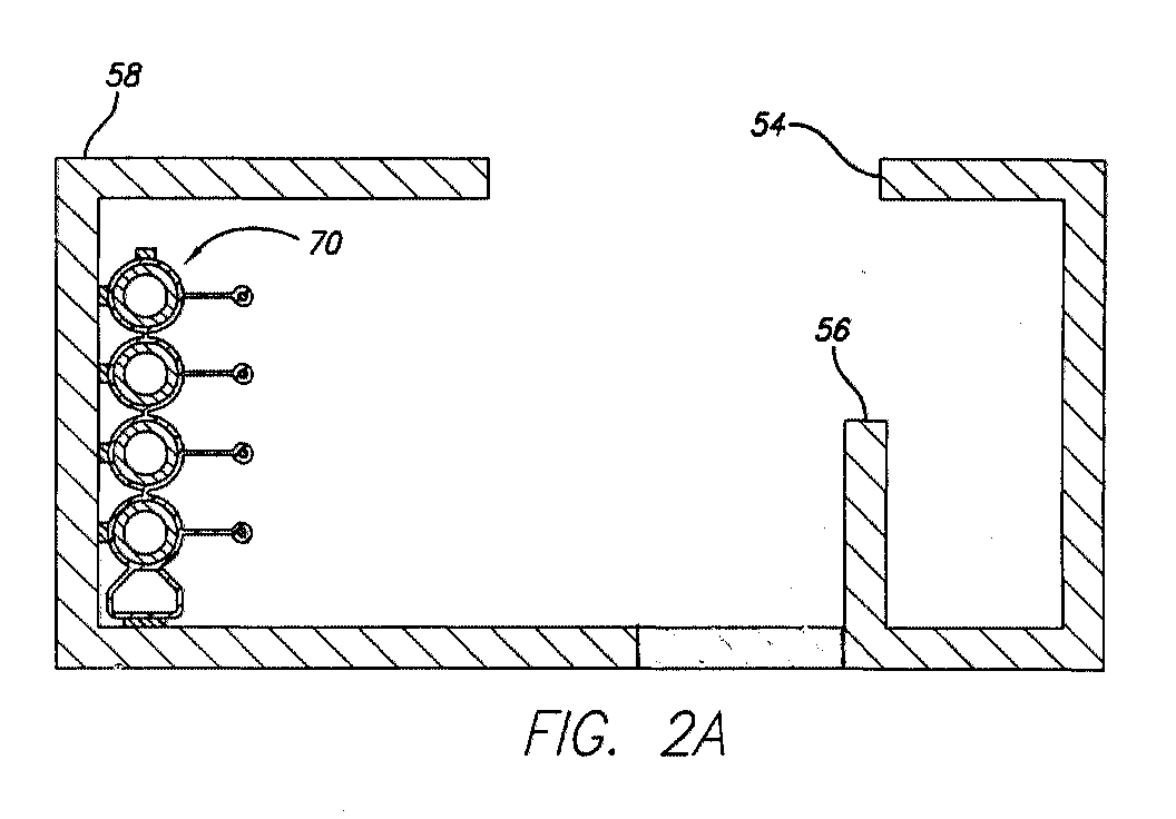
- Figure 2 is a top plan view of the printer with its cover removed to show the printhead carriage and unified ink tube guide and supports, Figures 2A and 2B comprising vertical cross sections at the lines indicated.
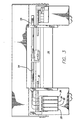
- Figure 3 is a front elevation view of the upper portion of the printer with cover removed to show the printhead carriage and attached printhead connector tubes.
- Figure 4 is a vertical cross-section taken at line 4 - 4 on Fig. 2 through the relevant portions of the printer showing the relative position of the carriage, the unitary tube guide and an arrangement having four ink delivery tubes.
- Figure 5 is a perspective of an anti-buckle tube carrier.
- Figure 6 is a perspective view of parallel multiple tube carriers.
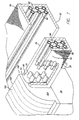
- Figure 7 is a perspective view of a tubes guide containing multiple tube carriers each having three tubes and an in-line tubes driver.
- Fig. 1 shows a large format printer 10 of the type which includes a transversely movable printhead carriage 30 (Fig. 2) enclosed by a plastic or metal hinged cover 12 which extends over a generally horizontally extending platen 14 over which printed media is discharged.
- a hinged cover 16 which contains four or more removable ink reservoirs 20, 22, 24, 26 which, through a flexible tube arrangement 40 - 46, supply ink to a number of different inkjet printheads mounted on the moveable carriage 30.
- each printhead is ordinarily connected to a single ink reservoir, in some instances it may be desirable to include more or less ink reservoirs than printheads so that, for increased ink capacity of, for example black ink, two black ink reservoirs may be connected by two separate black ink tubes to a single black ink printhead or two black ink printheads may be connected to a single black ink reservoir.
- Fig. 2 In the plan view of Fig. 2 in which the carriage cover 12 has been removed and in Fig. 4, it is seen that the printhead carriage 30 is mounted on a pair of transversely extending slider rods or guides 32, 34 which in turn are rigidly affixed to the frame of the printer. Also rigidly affixed to the frame of the printer are two or more tube guide support arches or bridges 47, 49 from which a unitary tube guide 50 is suspended in any suitable manner, for example, by brackets of desired configuration.
- the presently preferred embodiment of the unitary tube guide 50 essentially comprises a metal or other rigid structural box having a flat horizontally extending bottom wall 52 and generally vertically extending front and rear walls 54, 58 integrally formed therewith from a single piece or fabricated by welding or otherwise interconnecting separate pieces.
- the unitary tube guide 50 also has an upper tube confining surface such as generally horizontally extending top flanges connected to the side walls as will be described below.
- the tube guide 50 may be configured with a generally horizontal bottom and two or more upwardly extending side walls which may be angled toward each other to confine the tubes in the guide instead of the preferred embodiment guide 50 which has vertically extending side walls and horizontal top wall flanges.
- the unitary guide 50 has superior strength (shock and vibration) characteristics and improved grounding between the parts with no need for extra grounding straps.
- the presence of guide 50 prevents dirt and debris such as dust generated due to normal use of the tube carrier rubbing in the tube guides from falling onto the platen 14 or into a printhead service station 100 typically provided at the right end of the path of carriage travel.
- a vertically extending anti-buckling wall 56 is preferably formed parallel to the front wall 54 by upwardly bending a cutout section of the bottom wall 52.
- the anti-buckling wall 56 is considered necessary for 60" width printers and above.
- front wall 54 may be angled (in plan view) toward the back of the printer near its left end near the left bridge support 47 as shown in the above mentioned application Serial No. 08/240,039 to provide a clearance area for opening a printhead holddown cover 36 on the carriage 30 when the carriage is slid to a position proximate the left side of the platen 14 so that the printhead holddown cover can be easily opened for changing the printheads.
- a flexible ink delivery tube system conveys ink from the various separate ink reservoirs 20, 22, 24, 26 at the left side of the printer through four or more flexible ink tubes 40, 42, 44, 46 which extend from the ink reservoirs through the unitary tube guide 50 to the carriage 30 to convey ink to four (or more) printheads on the carriage 30.
- the entire ink tube delivery system may be a replaceable system as described and claimed in the aforementioned co-pending application Serial No. 09/240,039 filed January 29, 1999 by Gasso, et al (HP 60980039). It has been found that routing of the ink delivery tubes over the front wall 54 of the unified tubes carrier 50 facilitates replacement of the ink delivery system when necessary as compared with the structure shown in Serial No. 09/240,039.
- a printhead service station 80 At the right side of the printer is a printhead service station 80 at which the printhead carriage 30 may be parked for servicing such as wiping, spitting or priming the printheads.
- Each of the various ink reservoirs 20, 22, 24, 26 is easily accessible from the front of the printer when the reservoir cover 16 (seen in Fig. 1) is open so that the reservoirs can be easily removed to be refilled or replaced with new reservoirs.
- the reservoirs each contain a different base color of ink such as cyan, magenta and yellow or black so that a high number of colors can be produced as desired during printing.
- the bottom wall 52 of the guide 50 provides a support surface which extends in a horizontal plane for supporting substantially the entire moving length including the reverse bend of the ink delivery tubes 40, 42, 44, 46.
- the ink tubes are preferably bound together in a flexible wear resistant low friction anti-buckle tube carrier 70 to confine the tubes in a vertical plane and prevent wear as the tubes move in the guide 50.
- Compression buckling of the ink delivery tubes is known to occur in large printers due to the extreme generally unconfined (except by the unitary tubes guide 50) length of tubes which are repeatedly pulled and pushed by the printhead carriage 30. The tubes tend to buckle toward the back of the tubes guide 50. Elimination of the tube buckling problem, which at minimum results in deterioration of print quality and at maximum complete shutdown of printing, is achieved in part by the unitary tube guide described above and further by a unique anti-buckle tube carrier 70 to be described.
- the flexible ink delivery tubes 40, 42, 44, 46 are confined in the anti-buckle tube carrier 70 which is preferably permanently connected at the ink delivery end of the tubes to a printhead connector 100 which is a relatively rigid plastic part best seen in Figs. 4 and 7 - 10.
- the ink delivery tubes are preferably made of a linear low density polyethylene.
- the anti-buckle tube carrier 70 comprises a protective polypropylene sheath which encloses the flexible ink tubes at least along that portion of their length which is subject to buckling flex and includes an integrally molded wear resistant shoe 72 on the lowermost surface which is slidably supported on the bottom wall 52 of the unitary tube guide 50. As shown in Fig. 5, four ink tubes are arranged in parallel in one common plane.
- the anti-buckle tube carrier 70 also includes wear resistant lubricous ribs 74 on the top of the upper tube 40 and on the sides of all of the tubes 40, 42, 44, 46 which face the front guide wall 54.
- the ribs 74 are preferably made from polypropylene containing about 5% aramid fibers and 20% polytetrafluoroethylene (TEFLON).
- the material of the anti-buckle carrier 70 is preferably a polypropylene and EPDM compound which is both flexible and fatigue resistant.
- the above combination of materials for the carrier and ribs has been found to be considerably more quiet than prior art flexible ink delivery systems. Buckling is prevented by forming anti-buckling tension ribs 76 on the sides of the carrier opposite the lubricous ribs 74.
- the tension ribs 76 are much longer than the wear resistant ribs 74 and may be coextruded with a glass fiber cable 78 in each rib 76 if desired.
- FIG. 6 is a perspective view of a parallel carrier ink delivery system using multiple tube carriers 80, 90 each carrying three tubes 40, 42, 44; 41, 43, 45 arranged in a plane, the tubes in the two separate carriers being arranged in essentially parallel vertically extending planes which are spaced from each other to avoid rubbing in the reverse bend area of the ink delivery tubes.
- the carriers 80, 90 are not connected together and are permitted to separate along their lengths for flexibility, they are joined at the ink delivery ends to a printhead carriage connector unit 100.
- the outer carrier 80 also has lubricous ribs 82 at least on the sides of preferably all of the tubes which face the front guide wall 54.
- a wear shoe 72 and upper wear rib 74 like those shown in the four tube arrangement of Fig. 5 may also be provided.
- the inner carrier 90 preferably has lubricous ribs 92 on the sides of the tubes which face away from the carrier 80 which may contact the anti-buckling wall 56.
- the ribs 82, 92 may, like the ribs 74 described above, be made from polypropylene containing about 5% aramid fibers and 20% polytetrafluoroethylene (TEFLON).
- the material of the carriers or sheaths 80, 90 may be a polypropylene and EPDM compound which is both flexible and fatigue resistant.
- the anti-buckle tubes carrier 70 described above may be used as the inner carrier 90 as an alternative to the arrangement shown in Fig. 6. Also, like the anti-buckle tubes carrier 70 described above, parallel plane multiple tubes carriers 80, 90 can be used in tube guides of other configurations than the unitary tubes guide 50 described and shown herein.
- a carriage connector unit 100 (Fig. 7) which comprises one or more relatively rigid plastic parts which route the relatively flexible ink tubes from the tube guide 50 to the printhead carriage 30.
- the specific construction of the carriage connection end of the unit 100 is not part of the present invention but may take the form shown in the above mentioned co-pending application 08/240,039.
- a rigid arch or crane 102 extends over the top of the front wall 54 of the unitary tube guide 50 and interconnects the carriage connection 104 with a rigid block 106 having internal conduits (unnumbered) which each receive an ink tube extending therethrough.
- the conduits terminate at an in line tubes driver 130 having a generally flat end wall which is positioned in and aligned with the unitary tubes guide 50 between the front wall 54 and, if provided, the anti-buckle wall 56, such that the flat end wall is perpendicular to the length of the ink tubes which are passed through the conduits.
- the tubes carrier or carriers 80, 90 are preferably permanently connected to the flat end wall of the in line tubes driver 130 in any suitable manner, for example by cementing.
- the ink tubes extend through the conduits 110 - 120 in the carriage connector unit 100 and through the crane 102 to the carriage connection 104 for ink delivery to the printheads as is known in the art.
- the ink tubes are preferably arranged in side by side rows of three at the flat end wall of the in-line tubes driver 130; however, the tubes are routed in the connector unit 100 such that all six tubes are arranged in a common plane as they pass through the crane 102 so that the vertical dimension of the crane may be kept to a minimum where it passes over the front wall 54 of the unitary tubes guide 50.
- the drawings show the crane extending over the front wall of a tubes guide of the type shown in Figs.
- the carriage connector unit 100 may be configured to be used with other tube guide configurations, such, for example, as a tubes guide having a full height front wall and a shorter rear or anti-tube buckling wall.
- the crane is configured to extend over the top of the anti-buckling wall to the rear for attachment of the carriage connection 104 to the printhead carriage 30.
- use of a carriage connector unit 100 as shown and described herein which routs the tubes over the front wall 54 permits the use of a higher anti-buckling wall 56 than would be possible if the tubes were routed rearwardly over the top of the anti-buckling wall.
Landscapes
- Ink Jet (AREA)
Abstract
Description
- The present invention relates to the art of computer driven printers, particularly, large format color ink jet printers. Printers of this type have a printhead carriage which is mounted for reciprocal movement on the printer in a direction orthogonal to the direction of movement of the paper or other medium on which printing is to take place through the printer. The printer carriage of a color printer typically has four removable piezo-electric or thermal ink jet printheads mounted thereon. Each of the printheads contains a supply of ink which, for large scale printers, is generally inadequate due to the large volumes of ink which are required as compared with the ink supply requirements of desk top printers. Consequently, various means have been proposed for continuously or periodically refilling the carriage-borne printheads with ink. These systems fall into two categories. The first comprises offboard or off-axis ink reservoirs which are continuously connected to the carriage-borne or onboard printheads by flexible tubes. The second comprises a "take a gulp" system in which the printhead carriage is periodically moved to one end of its path of travel where it is then connected with off-axis ink reservoirs to fill the onboard printheads. This "take a gulp" system is disclosed in Hewlett-Packard's Designjet 2000 printer referred to in U.S. Patent Application Serial No. 08/805,861 filed March 3, 1997 and published in European Patent Publication No. 0863016 on September 9, 1998.
- Large format printers are expensive pieces of equipment which preferably should be capable of using different types of ink without significant down time of the printer when changing or replacing the ink delivery system or components thereof. The different ink types may for convenience be broadly referred to as indoor ink and outdoor ink, meaning ink intended to be used for production of drawings, posters, and other printed material which may be displayed outdoors or indoors. Outdoor ink is pigment based, i.e. containing a plurality of discrete undissolved pigment particles suspended in a fluid carrier. Dye-based ink has a lower degree of optical density and permanence but is less expensive. Since pigment based inks and dye-based inks are incompatible with each other, a system is desired which enables the use of either type of ink in a printer without cross-contamination of the printer inks by each other.
- Further, in color printers four or more separate colors of ink may be used comprising black and various primary or mid-primary colors such as cyan, magenta and yellow. In color ink printers provision must also be made to ensure that neither incorrect types of ink nor incorrect colors of ink can inadvertently be used in the system..
- Since the ink delivery tubes connected from offboard reservoirs to onboard printheads continually flex, leakage and breakage of the ink supply tubes may be experienced. A reliable ink delivery system and guides for routing the ink delivery tubes to minimize flexing, wear and damage of the ink tubes is desired. One such system is shown in U.S. patent application Serial No. 08/240,039 filed January 29, 1999 (HP 60980039) by Gasso, et al and owned by the assignee of the present invention.
- According to an aspect of the present invention it is provided an ink supply tube supporting and guiding system for a large format printer comprising: a unitary tube support and guide having a first tube guide surface, a tube support surface and a second tube guide surface, said first and said second tube guide surfaces spaced apart to define an ink tube support and guide area therebetween; said tube support surface including an anti-buckling wall to confine movement of a portion of the length of the ink delivery tubes to a guide area between said first tube guide surface and said anti-buckling wall.
- According to a second aspect of the invention it is provided a ink delivery system for an inkjet printer which includes a plurality of ink tubes supported in a tube guide and extending from ink supply reservoirs to inkjet printheads on board a moveable printhead carriage, said ink delivery system comprising a carriage connector unit having an in-line tubes driver positioned in and aligned with said tubes in said tube guide, said carriage connector unit including a rigid arm having a plurality of said ink tubes therein arranged in a common plane, said arm going beyond an extending wall of said guide for conveying ink to said printheads.
- According to a third aspect of the invention it is provided a ink jet printer comprising the ink delivery system above referenced.
- Figure 1 is a perspective view of a large format printer in which the present invention is useful.
- Figure 2 is a top plan view of the printer with its cover removed to show the printhead carriage and unified ink tube guide and supports, Figures 2A and 2B comprising vertical cross sections at the lines indicated.
- Figure 3 is a front elevation view of the upper portion of the printer with cover removed to show the printhead carriage and attached printhead connector tubes.
- Figure 4 is a vertical cross-section taken at line 4 - 4 on Fig. 2 through the relevant portions of the printer showing the relative position of the carriage, the unitary tube guide and an arrangement having four ink delivery tubes.
- Figure 5 is a perspective of an anti-buckle tube carrier.
- Figure 6 is a perspective view of parallel multiple tube carriers.
- Figure 7 is a perspective view of a tubes guide containing multiple tube carriers each having three tubes and an in-line tubes driver.
- Fig. 1 shows a
large format printer 10 of the type which includes a transversely movable printhead carriage 30 (Fig. 2) enclosed by a plastic or metal hingedcover 12 which extends over a generally horizontally extendingplaten 14 over which printed media is discharged. At the left side of the platen is ahinged cover 16 which contains four or moreremovable ink reservoirs moveable carriage 30. While each printhead is ordinarily connected to a single ink reservoir, in some instances it may be desirable to include more or less ink reservoirs than printheads so that, for increased ink capacity of, for example black ink, two black ink reservoirs may be connected by two separate black ink tubes to a single black ink printhead or two black ink printheads may be connected to a single black ink reservoir. - In the plan view of Fig. 2 in which the
carriage cover 12 has been removed and in Fig. 4, it is seen that theprinthead carriage 30 is mounted on a pair of transversely extending slider rods orguides bridges unitary tube guide 50 is suspended in any suitable manner, for example, by brackets of desired configuration. The presently preferred embodiment of theunitary tube guide 50 essentially comprises a metal or other rigid structural box having a flat horizontally extendingbottom wall 52 and generally vertically extending front andrear walls unitary tube guide 50 also has an upper tube confining surface such as generally horizontally extending top flanges connected to the side walls as will be described below. Alternatively, thetube guide 50 may be configured with a generally horizontal bottom and two or more upwardly extending side walls which may be angled toward each other to confine the tubes in the guide instead of thepreferred embodiment guide 50 which has vertically extending side walls and horizontal top wall flanges. Theunitary guide 50 has superior strength (shock and vibration) characteristics and improved grounding between the parts with no need for extra grounding straps. In addition, the presence ofguide 50 prevents dirt and debris such as dust generated due to normal use of the tube carrier rubbing in the tube guides from falling onto theplaten 14 or into aprinthead service station 100 typically provided at the right end of the path of carriage travel. - A vertically extending
anti-buckling wall 56 is preferably formed parallel to thefront wall 54 by upwardly bending a cutout section of thebottom wall 52. Theanti-buckling wall 56 is considered necessary for 60" width printers and above. Near one end of theunified tubes guide 50, spaced horizontally extendingtop flanges rear walls rear wall 58 of the tube guide and the tubes in the section which is uncovered by the top flange. - Although not shown in the drawings which depict a
unitary guide 50 having a straightfront wall 54, persons skilled in the art will recognize that thefront wall 54 may be angled (in plan view) toward the back of the printer near its left end near theleft bridge support 47 as shown in the above mentioned application Serial No. 08/240,039 to provide a clearance area for opening a printhead holddown cover 36 on thecarriage 30 when the carriage is slid to a position proximate the left side of theplaten 14 so that the printhead holddown cover can be easily opened for changing the printheads. - A flexible ink delivery tube system conveys ink from the various
separate ink reservoirs flexible ink tubes unitary tube guide 50 to thecarriage 30 to convey ink to four (or more) printheads on thecarriage 30. The entire ink tube delivery system may be a replaceable system as described and claimed in the aforementioned co-pending application Serial No. 09/240,039 filed January 29, 1999 by Gasso, et al (HP 60980039). It has been found that routing of the ink delivery tubes over thefront wall 54 of theunified tubes carrier 50 facilitates replacement of the ink delivery system when necessary as compared with the structure shown in Serial No. 09/240,039. - At the right side of the printer is a
printhead service station 80 at which theprinthead carriage 30 may be parked for servicing such as wiping, spitting or priming the printheads. Each of thevarious ink reservoirs - As best seen in Figs. 2 and 4, the
bottom wall 52 of theguide 50 provides a support surface which extends in a horizontal plane for supporting substantially the entire moving length including the reverse bend of theink delivery tubes anti-buckle tube carrier 70 to confine the tubes in a vertical plane and prevent wear as the tubes move in theguide 50. - Compression buckling of the ink delivery tubes is known to occur in large printers due to the extreme generally unconfined (except by the unitary tubes guide 50) length of tubes which are repeatedly pulled and pushed by the
printhead carriage 30. The tubes tend to buckle toward the back of thetubes guide 50. Elimination of the tube buckling problem, which at minimum results in deterioration of print quality and at maximum complete shutdown of printing, is achieved in part by the unitary tube guide described above and further by a uniqueanti-buckle tube carrier 70 to be described. - The flexible
ink delivery tubes anti-buckle tube carrier 70 which is preferably permanently connected at the ink delivery end of the tubes to aprinthead connector 100 which is a relatively rigid plastic part best seen in Figs. 4 and 7 - 10. The ink delivery tubes are preferably made of a linear low density polyethylene. Theanti-buckle tube carrier 70 comprises a protective polypropylene sheath which encloses the flexible ink tubes at least along that portion of their length which is subject to buckling flex and includes an integrally molded wearresistant shoe 72 on the lowermost surface which is slidably supported on thebottom wall 52 of theunitary tube guide 50. As shown in Fig. 5, four ink tubes are arranged in parallel in one common plane. Other arrangements are of course possible and although the drawings depict use of theanti-buckle tube carrier 70 in aunitary tube guide 50 as described above, persons skilled in the art will recognize that theanti-buckle tubes carrier 70 described herein can also be used in other configurations of tube guides such, for example, as the one shown in the aforementioned U.S. patent application Serial No. 09/240,039. Theanti-buckle tube carrier 70 also includes wear resistantlubricous ribs 74 on the top of theupper tube 40 and on the sides of all of thetubes front guide wall 54. Theribs 74 are preferably made from polypropylene containing about 5% aramid fibers and 20% polytetrafluoroethylene (TEFLON). The material of theanti-buckle carrier 70 is preferably a polypropylene and EPDM compound which is both flexible and fatigue resistant. The above combination of materials for the carrier and ribs has been found to be considerably more quiet than prior art flexible ink delivery systems. Buckling is prevented by forminganti-buckling tension ribs 76 on the sides of the carrier opposite thelubricous ribs 74. Thetension ribs 76 are much longer than the wearresistant ribs 74 and may be coextruded with aglass fiber cable 78 in eachrib 76 if desired. - Forces imparted to the ink tubes as the carriage moves to the right from the left end of its path of travel place the ink tubes in compression which tends to induce buckling of the tubes toward the
anti-buckling wall 56 of thetube guide 50. Buckling of the ink tubes is resisted by increasing tension in theribs 76 and cables 78 (if provided) as bending begins to take place. Conversely, when the tubes are bent in the reverse direction at the right end of the printer, thetension ribs 76 are placed in compression and tend to collapse since the ribs are not designed to resist compression so as to permit the necessary flexing of thetubes - It is advantageous, particularly in the design of printers which have more than four separate ink reservoirs, ink delivery systems and printheads, to arrange the ink delivery system tubes other than in a single plane. Figure 6 is a perspective view of a parallel carrier ink delivery system using
multiple tube carriers tubes carriers carriage connector unit 100. Theouter carrier 80 also haslubricous ribs 82 at least on the sides of preferably all of the tubes which face thefront guide wall 54. Awear shoe 72 andupper wear rib 74 like those shown in the four tube arrangement of Fig. 5 may also be provided. Theinner carrier 90 preferably haslubricous ribs 92 on the sides of the tubes which face away from thecarrier 80 which may contact theanti-buckling wall 56. Theribs ribs 74 described above, be made from polypropylene containing about 5% aramid fibers and 20% polytetrafluoroethylene (TEFLON). The material of the carriers orsheaths anti-buckle tubes carrier 70 described above may be used as theinner carrier 90 as an alternative to the arrangement shown in Fig. 6. Also, like theanti-buckle tubes carrier 70 described above, parallel planemultiple tubes carriers - Control of the ink delivery system tubes is further improved by provision of a carriage connector unit 100 (Fig. 7) which comprises one or more relatively rigid plastic parts which route the relatively flexible ink tubes from the
tube guide 50 to theprinthead carriage 30. The specific construction of the carriage connection end of theunit 100 is not part of the present invention but may take the form shown in the above mentioned co-pending application 08/240,039. A rigid arch orcrane 102 extends over the top of thefront wall 54 of theunitary tube guide 50 and interconnects thecarriage connection 104 with arigid block 106 having internal conduits (unnumbered) which each receive an ink tube extending therethrough. The conduits terminate at an in line tubes driver 130 having a generally flat end wall which is positioned in and aligned with the unitary tubes guide 50 between thefront wall 54 and, if provided, theanti-buckle wall 56, such that the flat end wall is perpendicular to the length of the ink tubes which are passed through the conduits. The tubes carrier orcarriers - The ink tubes extend through the conduits 110 - 120 in the
carriage connector unit 100 and through thecrane 102 to thecarriage connection 104 for ink delivery to the printheads as is known in the art. The ink tubes are preferably arranged in side by side rows of three at the flat end wall of the in-line tubes driver 130; however, the tubes are routed in theconnector unit 100 such that all six tubes are arranged in a common plane as they pass through thecrane 102 so that the vertical dimension of the crane may be kept to a minimum where it passes over thefront wall 54 of the unitary tubes guide 50. Although the drawings show the crane extending over the front wall of a tubes guide of the type shown in Figs. 2 - 4, persons skilled in the art will understand that thecarriage connector unit 100 may be configured to be used with other tube guide configurations, such, for example, as a tubes guide having a full height front wall and a shorter rear or anti-tube buckling wall. In such an arrangement the crane is configured to extend over the top of the anti-buckling wall to the rear for attachment of thecarriage connection 104 to theprinthead carriage 30. It will also be understood that use of acarriage connector unit 100 as shown and described herein which routs the tubes over thefront wall 54 permits the use of ahigher anti-buckling wall 56 than would be possible if the tubes were routed rearwardly over the top of the anti-buckling wall. - Although the presently preferred embodiments of the invention have been shown and described in detail, those skilled in the art will appreciate that various modifications may be made without departing from the spirit and scope of the invention which is defined in the appended claims.
Claims (12)
- An ink supply tube supporting and guiding system for a large format printer comprising: a unitary tube support and guide having a first tube guide surface, a tube support surface and a second tube guide surface, said first and said second tube guide surfaces spaced apart to define an ink tube support and guide area therebetween; said tube support surface including an anti-buckling wall to confine movement of a portion of the length of the ink delivery tubes to a guide area between said first tube guide surface and said anti-buckling wall.
- The guiding system of claim 1, wherein said support structure comprises spaced bridge supports, said unitary tube guide being suspended by connection of said upper tube guide support surfaces to said bridge supports on a printer above the path of movement of a printhead carriage.
- An ink delivery system for an inkjet printer which includes a plurality of ink tubes supported in a tube guide and extending from ink supply reservoirs to inkjet printheads on board a moveable printhead carriage, said ink delivery system comprising a carriage connector unit having an in-line tubes driver positioned in and aligned with said tubes in said tube guide, said carriage connector unit including a rigid arm having a plurality of said ink tubes therein arranged in a common plane, said arm going beyond an extending wall of said guide for conveying ink to said printheads.
- The ink delivery system of claim 3, wherein said ink tubes pass through said in-line driver in an arrangement having parallel upwardly extending rows of said ink tubes.
- The ink delivery system of claim 3, wherein said carriage connector unit guides said tubes without kinking from a first position in said tubes guide from a direction extending generally parallel to the direction of movement of said printhead carriage upwardly and transversely over said upwardly extending wall of said guide and said tubes terminate in a generally downwardly extending direction for connection to said printheads.
- The ink delivery system of any claims from 3 to 5, wherein said ink tubes are arranged in at least one group extending in a first extending plane, said tubes being bound together along a portion of their length by an anti- buckle tubes carrier.
- The ink delivery system of claim 6, wherein said carrier comprising a protective sheath having integrally formed stretch resistant tension ribs connected to and extending from one side of said carrier a distance sufficient for resisting bending of said carrier and tubes convexly toward said tension ribs, said tension ribs having insignificant compression resistance to permit bending of said carrier and tubes toward said tension ribs.
- The ink delivery system of claims 6 and 7, further comprising tension reinforcing cables in said tension ribs.
- The ink delivery system of any claims from 6 to 8, further comprising wear resistant shoes on lower and upper surfaces of said carrier for slidably contacting a tube guide.
- The ink delivery system of any claims from 6 to 9 wherein said ink tubes are arranged in a plurality of groups, said tubes being arranged in each group in a first extending plain and said groups being arranged in a second extending plains.
- The ink delivery system of claim 10, wherein said first extending plane is generally perpendicular with respect said second extending plane.
- An ink jet printer comprising the ink delivery system of any claims form 3 to 11.
Applications Claiming Priority (2)
| Application Number | Priority Date | Filing Date | Title |
|---|---|---|---|
| US571038 | 1984-01-16 | ||
| US09/571,038 US6338553B1 (en) | 2000-05-15 | 2000-05-15 | Ink supply tube guiding system for large format printer |
Publications (2)
| Publication Number | Publication Date |
|---|---|
| EP1172218A1 true EP1172218A1 (en) | 2002-01-16 |
| EP1172218B1 EP1172218B1 (en) | 2007-09-05 |
Family
ID=24282068
Family Applications (1)
| Application Number | Title | Priority Date | Filing Date |
|---|---|---|---|
| EP01111761A Expired - Lifetime EP1172218B1 (en) | 2000-05-15 | 2001-05-15 | One piece tubes guide |
Country Status (3)
| Country | Link |
|---|---|
| US (1) | US6338553B1 (en) |
| EP (1) | EP1172218B1 (en) |
| DE (1) | DE60130290T2 (en) |
Cited By (3)
| Publication number | Priority date | Publication date | Assignee | Title |
|---|---|---|---|---|
| EP1442890A1 (en) * | 2003-02-03 | 2004-08-04 | Seiko Epson Corporation | Liquid supplying member, method of manufacturing the same, and liquid ejection apparatus incorporating the same |
| US7201475B2 (en) | 2002-02-28 | 2007-04-10 | Seiko Epson Corporation | Liquid supplying member, method of manufacturing the same, and liquid ejection apparatus incorporating the same |
| US7273271B2 (en) | 2002-02-28 | 2007-09-25 | Seiko Epson Corporation | Liquid supplying member, method of manufacturing the same, and liquid ejection apparatus incorporating the same |
Families Citing this family (19)
| Publication number | Priority date | Publication date | Assignee | Title |
|---|---|---|---|---|
| JP3849676B2 (en) * | 2002-10-01 | 2006-11-22 | セイコーエプソン株式会社 | Droplet ejection device, electro-optical device manufacturing method, electro-optical device, and electronic apparatus |
| US20050219281A1 (en) | 2004-03-24 | 2005-10-06 | Takeo Seino | Attachment and liquid supplying |
| CN2759784Y (en) * | 2005-01-22 | 2006-02-22 | 珠海天威飞马打印耗材有限公司 | Positioning holder for inking pipe of printer |
| CN102896903B (en) * | 2008-03-25 | 2015-07-01 | 精工爱普生株式会社 | Liquid supply flow path device and liquid ejecting apparatus using the same |
| JP6182839B2 (en) * | 2012-08-31 | 2017-08-23 | セイコーエプソン株式会社 | Ink supply device |
| USD723100S1 (en) * | 2012-10-31 | 2015-02-24 | Ricoh Company, Ltd. | Printer |
| JP6111748B2 (en) * | 2013-03-07 | 2017-04-12 | セイコーエプソン株式会社 | Liquid container container, liquid supply device, and liquid ejection device |
| JP6171442B2 (en) * | 2013-03-21 | 2017-08-02 | セイコーエプソン株式会社 | Liquid ejection device |
| JP6330275B2 (en) * | 2013-08-29 | 2018-05-30 | セイコーエプソン株式会社 | Recording device |
| WO2017036487A1 (en) | 2015-09-02 | 2017-03-09 | Hewlett-Packard Development Company, L.P. | Printing fluid supply carrier |
| US10343430B2 (en) * | 2016-09-22 | 2019-07-09 | Océ Holding B.V. | Assembly for moving a carriage |
| JP7215197B2 (en) * | 2019-02-06 | 2023-01-31 | セイコーエプソン株式会社 | recording device |
| JP7172792B2 (en) * | 2019-03-27 | 2022-11-16 | セイコーエプソン株式会社 | printer |
| JP7243384B2 (en) * | 2019-03-29 | 2023-03-22 | セイコーエプソン株式会社 | printer |
| USD986963S1 (en) * | 2020-05-13 | 2023-05-23 | Hewlett-Packard Development Company, L.P. | Large format printer |
| USD981481S1 (en) * | 2020-05-14 | 2023-03-21 | Hewlett-Packard Development Company, L.P. | Large format printer |
| USD984528S1 (en) * | 2020-05-14 | 2023-04-25 | Hewlett-Packard Development Company, L.P. | Large format printer |
| USD973131S1 (en) * | 2020-05-15 | 2022-12-20 | Hewlett-Packard Development Company, L.P. | Frame for an output collection system of a large format printer |
| JP1689944S (en) * | 2020-09-18 | 2021-07-12 |
Citations (6)
| Publication number | Priority date | Publication date | Assignee | Title |
|---|---|---|---|---|
| US5025270A (en) * | 1988-06-27 | 1991-06-18 | Seiko Instruments, Inc. | Recording apparatus coupled ink supply tubes |
| JPH11157288A (en) * | 1997-11-25 | 1999-06-15 | Mutoh Ind Ltd | Ink tube piping device in plotter |
| JPH11268288A (en) * | 1998-03-25 | 1999-10-05 | Brother Ind Ltd | Printing device and cartridge member |
| JPH11286101A (en) * | 1998-03-31 | 1999-10-19 | Brother Ind Ltd | Printing device |
| US5992990A (en) * | 1996-10-24 | 1999-11-30 | Hewlett-Packard Company | Ink delivery system having an off-carriage pressure regulator |
| US6003981A (en) * | 1996-08-30 | 1999-12-21 | Hewlett-Packard Company | Replaceable module for a printing composition delivery system of a printing device |
Family Cites Families (7)
| Publication number | Priority date | Publication date | Assignee | Title |
|---|---|---|---|---|
| US3102770A (en) * | 1960-02-12 | 1963-09-03 | Honeywell Regulator Co | Recorder ink supply |
| US4831389A (en) | 1987-12-21 | 1989-05-16 | Hewlett-Packard Company | Off board ink supply system and process for operating an ink jet printer |
| WO1995011424A1 (en) | 1993-10-20 | 1995-04-27 | Lasermaster Corporation | Automatic ink refill system for disposable ink jet cartridges |
| US5369429A (en) | 1993-10-20 | 1994-11-29 | Lasermaster Corporation | Continuous ink refill system for disposable ink jet cartridges having a predetermined ink capacity |
| US5489931A (en) | 1994-05-26 | 1996-02-06 | Hewlett-Packard Company | Fluid delivery system including coiled concentric tubes |
| US6007190A (en) * | 1994-12-29 | 1999-12-28 | Encad, Inc. | Ink supply system for an ink jet printer having large volume ink containers |
| US5686947A (en) | 1995-05-03 | 1997-11-11 | Encad, Inc. | Ink jet printer incorporating high volume ink reservoirs |
-
2000
- 2000-05-15 US US09/571,038 patent/US6338553B1/en not_active Expired - Fee Related
-
2001
- 2001-05-15 DE DE60130290T patent/DE60130290T2/en not_active Expired - Fee Related
- 2001-05-15 EP EP01111761A patent/EP1172218B1/en not_active Expired - Lifetime
Patent Citations (6)
| Publication number | Priority date | Publication date | Assignee | Title |
|---|---|---|---|---|
| US5025270A (en) * | 1988-06-27 | 1991-06-18 | Seiko Instruments, Inc. | Recording apparatus coupled ink supply tubes |
| US6003981A (en) * | 1996-08-30 | 1999-12-21 | Hewlett-Packard Company | Replaceable module for a printing composition delivery system of a printing device |
| US5992990A (en) * | 1996-10-24 | 1999-11-30 | Hewlett-Packard Company | Ink delivery system having an off-carriage pressure regulator |
| JPH11157288A (en) * | 1997-11-25 | 1999-06-15 | Mutoh Ind Ltd | Ink tube piping device in plotter |
| JPH11268288A (en) * | 1998-03-25 | 1999-10-05 | Brother Ind Ltd | Printing device and cartridge member |
| JPH11286101A (en) * | 1998-03-31 | 1999-10-19 | Brother Ind Ltd | Printing device |
Non-Patent Citations (2)
| Title |
|---|
| PATENT ABSTRACTS OF JAPAN vol. 1999, no. 11 30 September 1999 (1999-09-30) * |
| PATENT ABSTRACTS OF JAPAN vol. 2000, no. 01 31 January 2000 (2000-01-31) * |
Cited By (4)
| Publication number | Priority date | Publication date | Assignee | Title |
|---|---|---|---|---|
| US7201475B2 (en) | 2002-02-28 | 2007-04-10 | Seiko Epson Corporation | Liquid supplying member, method of manufacturing the same, and liquid ejection apparatus incorporating the same |
| US7273271B2 (en) | 2002-02-28 | 2007-09-25 | Seiko Epson Corporation | Liquid supplying member, method of manufacturing the same, and liquid ejection apparatus incorporating the same |
| US7413296B2 (en) | 2002-02-28 | 2008-08-19 | Seiko Epson Corporation | Liquid supplying member, method of manufacturing the same, and liquid ejection apparatus incorporating the same |
| EP1442890A1 (en) * | 2003-02-03 | 2004-08-04 | Seiko Epson Corporation | Liquid supplying member, method of manufacturing the same, and liquid ejection apparatus incorporating the same |
Also Published As
| Publication number | Publication date |
|---|---|
| DE60130290T2 (en) | 2008-05-29 |
| EP1172218B1 (en) | 2007-09-05 |
| US6338553B1 (en) | 2002-01-15 |
| DE60130290D1 (en) | 2007-10-18 |
Similar Documents
| Publication | Publication Date | Title |
|---|---|---|
| EP1172218B1 (en) | One piece tubes guide | |
| US6247802B1 (en) | Ink supply tube guiding system for large format printer | |
| US6007190A (en) | Ink supply system for an ink jet printer having large volume ink containers | |
| US6565197B1 (en) | Ink jet printer incorporating high volume ink reservoirs | |
| US6402277B1 (en) | Ink leak detection system in inkjet printing devices | |
| US7703869B2 (en) | Image forming devices | |
| CN101445005B (en) | Image forming apparatus | |
| JP3572854B2 (en) | Inkjet printer and damper | |
| US7540587B2 (en) | Liquid passage forming member guiding device | |
| JP2008049560A (en) | Image forming apparatus | |
| JP5919758B2 (en) | Image forming apparatus | |
| JP5220137B2 (en) | Liquid ejector | |
| JP6263938B2 (en) | Image recording device | |
| US8517520B2 (en) | Liquid jetting apparatus | |
| JP2013154573A (en) | Recording apparatus | |
| JPH04129751A (en) | inkjet recording device | |
| JP7547432B2 (en) | Recording device | |
| US20100110143A1 (en) | Liquid Discharge Apparatus | |
| US20040061739A1 (en) | Carriages for printing devices | |
| JP3417456B2 (en) | Carriage cover for inkjet color printer | |
| JP5670823B2 (en) | Inkjet recording device | |
| JP6056880B2 (en) | Liquid ejector | |
| JP2007160552A (en) | Ink supply apparatus and ink jet recording apparatus | |
| JP5867378B2 (en) | Liquid ejector | |
| JP2021104593A (en) | Recording device |
Legal Events
| Date | Code | Title | Description |
|---|---|---|---|
| PUAI | Public reference made under article 153(3) epc to a published international application that has entered the european phase |
Free format text: ORIGINAL CODE: 0009012 |
|
| AK | Designated contracting states |
Kind code of ref document: A1 Designated state(s): AT BE CH CY DE DK ES FI FR GB GR IE IT LI LU MC NL PT SE TR Kind code of ref document: A1 Designated state(s): DE FR GB IT |
|
| AX | Request for extension of the european patent |
Free format text: AL;LT;LV;MK;RO;SI |
|
| 17P | Request for examination filed |
Effective date: 20020705 |
|
| AKX | Designation fees paid |
Free format text: DE FR GB IT |
|
| 17Q | First examination report despatched |
Effective date: 20040907 |
|
| GRAP | Despatch of communication of intention to grant a patent |
Free format text: ORIGINAL CODE: EPIDOSNIGR1 |
|
| GRAS | Grant fee paid |
Free format text: ORIGINAL CODE: EPIDOSNIGR3 |
|
| GRAA | (expected) grant |
Free format text: ORIGINAL CODE: 0009210 |
|
| AK | Designated contracting states |
Kind code of ref document: B1 Designated state(s): DE FR GB IT |
|
| REG | Reference to a national code |
Ref country code: GB Ref legal event code: FG4D |
|
| RIN1 | Information on inventor provided before grant (corrected) |
Inventor name: LEWIS, RICHARD H. Inventor name: TORGERSSON, CURT Inventor name: MONCLUS, ANTONI Inventor name: GARCIA, JESUS Inventor name: URRUTIA, MARTIN |
|
| RIN2 | Information on inventor provided after grant (corrected) |
Inventor name: LEWIS, RICHARD H. Inventor name: MONCLUS, ANTONI Inventor name: GARCIA, JESUS Inventor name: TORGERSSON, CURT Inventor name: URRUTIA, MARTIN |
|
| REF | Corresponds to: |
Ref document number: 60130290 Country of ref document: DE Date of ref document: 20071018 Kind code of ref document: P |
|
| EN | Fr: translation not filed | ||
| PLBE | No opposition filed within time limit |
Free format text: ORIGINAL CODE: 0009261 |
|
| STAA | Information on the status of an ep patent application or granted ep patent |
Free format text: STATUS: NO OPPOSITION FILED WITHIN TIME LIMIT |
|
| 26N | No opposition filed |
Effective date: 20080606 |
|
| PG25 | Lapsed in a contracting state [announced via postgrant information from national office to epo] |
Ref country code: FR Free format text: LAPSE BECAUSE OF FAILURE TO SUBMIT A TRANSLATION OF THE DESCRIPTION OR TO PAY THE FEE WITHIN THE PRESCRIBED TIME-LIMIT Effective date: 20080502 |
|
| GBPC | Gb: european patent ceased through non-payment of renewal fee |
Effective date: 20080515 |
|
| PG25 | Lapsed in a contracting state [announced via postgrant information from national office to epo] |
Ref country code: DE Free format text: LAPSE BECAUSE OF NON-PAYMENT OF DUE FEES Effective date: 20081202 |
|
| PG25 | Lapsed in a contracting state [announced via postgrant information from national office to epo] |
Ref country code: GB Free format text: LAPSE BECAUSE OF NON-PAYMENT OF DUE FEES Effective date: 20080515 |
|
| PG25 | Lapsed in a contracting state [announced via postgrant information from national office to epo] |
Ref country code: IT Free format text: LAPSE BECAUSE OF NON-PAYMENT OF DUE FEES Effective date: 20080531 |