EP1172044A2 - Schwenkvorrichtung für ein Gerät - Google Patents
Schwenkvorrichtung für ein Gerät Download PDFInfo
- Publication number
- EP1172044A2 EP1172044A2 EP01116923A EP01116923A EP1172044A2 EP 1172044 A2 EP1172044 A2 EP 1172044A2 EP 01116923 A EP01116923 A EP 01116923A EP 01116923 A EP01116923 A EP 01116923A EP 1172044 A2 EP1172044 A2 EP 1172044A2
- Authority
- EP
- European Patent Office
- Prior art keywords
- joint part
- coupling
- cone
- upper joint
- curve
- Prior art date
- Legal status (The legal status is an assumption and is not a legal conclusion. Google has not performed a legal analysis and makes no representation as to the accuracy of the status listed.)
- Granted
Links
- 230000008878 coupling Effects 0.000 claims abstract description 36
- 238000010168 coupling process Methods 0.000 claims abstract description 36
- 238000005859 coupling reaction Methods 0.000 claims abstract description 36
- 230000006835 compression Effects 0.000 claims abstract description 11
- 238000007906 compression Methods 0.000 claims abstract description 11
- 230000000295 complement effect Effects 0.000 claims abstract description 4
- 230000001681 protective effect Effects 0.000 claims description 5
- 238000004804 winding Methods 0.000 claims description 2
- 206010033307 Overweight Diseases 0.000 description 4
- 230000000750 progressive effect Effects 0.000 description 3
- 238000004519 manufacturing process Methods 0.000 description 2
- 208000008589 Obesity Diseases 0.000 description 1
- 230000005540 biological transmission Effects 0.000 description 1
- 239000003517 fume Substances 0.000 description 1
- 238000002347 injection Methods 0.000 description 1
- 239000007924 injection Substances 0.000 description 1
- 238000009434 installation Methods 0.000 description 1
- 235000020824 obesity Nutrition 0.000 description 1
- 239000000243 solution Substances 0.000 description 1
Images




Classifications
-
- A—HUMAN NECESSITIES
- A45—HAND OR TRAVELLING ARTICLES
- A45D—HAIRDRESSING OR SHAVING EQUIPMENT; EQUIPMENT FOR COSMETICS OR COSMETIC TREATMENTS, e.g. FOR MANICURING OR PEDICURING
- A45D20/00—Hair drying devices; Accessories therefor
- A45D20/22—Helmets with hot air supply or ventilating means, e.g. electrically heated air current
- A45D20/32—Supporting or fastening of the helmets
Definitions
- the invention relates to a device according to the preamble of the preamble Claim 1.
- Such a device is known from DE-1059159-B.
- This device is used to move a device from a first position ("parking position") to a second Position ("working position”) and vice versa.
- parking position a first position
- working position a second Position
- a device for compensation works in this device the excess weight of the device which can be pivoted about a horizontal axis an upper joint part by means of a force of a compression spring very imprecise and can only be used inflexibly, since the device with the Device and a support element forms a mounting unit, which is also too high Manufacturing costs leads.
- the invention is therefore based on the object of a generic type To create device that does not have the disadvantages mentioned above.
- the lower joint part is provided with a piston which by the compression spring slidably with a curve part arranged in the upper joint part is in frictional engagement, the curve part such a curve shows that there is a constant balance of excess weight, that the Compression spring biased by means of an adjusting screw and a non-rotatable nut is and is supported as a counter bearing on a cone, the cone in a complementary receptacle at the lower end of the lower joint part is arranged that the cone is provided with slots that it like A collet acts on the set screw, which is not in this area
- Has thread that the lower joint part with a first coupling part for a support element and the upper joint part with a second coupling part for the device is provided and that the lower and the upper joint part as one Structural unit is a device with a well working Device to compensate for an overweight and with diverse Possible uses in addition to low manufacturing costs especially the device from a parking position to a working position can fall.
- a spring force adjustment device is assigned to the piston individually adjust an overweight of a device, whereby preferably the spring force adjusting device is provided with an adjusting screw is that from the lower end of the lower joint part with a tool is adjustable.
- the lower joint part is with a Cable entry is provided. being for a parking position of the device either the lower joint part is provided with a cable wrap holder.
- the device is connected to a third coupling part for the device Coupling with the corresponding second coupling part of the upper one Joint part.
- the device has a protective covering such that the first and the second joint part with a partially overlapping spherical shell-like Cover is provided, which is preferably made of plastic.
- the device is a hair treatment device, for example a hair dryer hood or a steam hood or a lamp, for example a Operating light or a PC monitor, for example a flat screen (LCD) monitor, intended.
- a hair treatment device for example a hair dryer hood or a steam hood or a lamp
- a Operating light or a PC monitor for example a flat screen (LCD) monitor
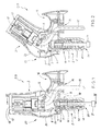
- FIG. 1 shows a device 1 in a working position with a lower and an upper hinge part 2,3, a device 4 for Compensation for an overweight around a horizontal axis X pivotable device 5 (Fig.10) over the upper hinge part 3 by means of a force a compression spring 6 is provided.
- the lower joint part 2 is with a piston 7 provided by the compression spring 6 with one in the upper joint part 3 arranged curve part 8 is slidably in frictional engagement, the curve part 8 has such a curve 9 that a constant compensation of the Obesity occurs.
- the compression spring 6 is by means of an adjusting screw 21 and a torsionally fixed nut 40 and is supported as a counter bearing on one Cone 41, the cone 41 in a complementary receptacle 42 is arranged at the lower end of the lower joint part 2 that the cone 41st is provided with slots 43 that it like a collet on the Set screw 21 acts, which has no thread in this area, whereby from the park position to the working position there is a progressive friction that a Prevents the device 25-31 from falling into a working position.
- the lower joint part 2 is with a first coupling part 10 for a support element 11 (Fig.10) and that provide the upper joint part 3 with a second coupling part 12 for the device 5, the lower and the upper joint part 2, 3 as a structural unit 13 is trained.
- Such swivel devices are used, for example, for movable connection used by hair dryers with tripods and allow a comfortable Position the device. So far, the non-progressive has been a disadvantage Torque curve when turning or tilting the joint, which is caused by a elaborate friction has to be compensated in order to tilt the To avoid device. This friction is in the previously known solutions for all angles of rotation are the same size (but a device attached to the joint produces a progressive torque).
- the movement of the piston 7 is not linear with the Angle of rotation of the joint 2.3, but progressively through the special shape of the Sliding surface.
- the fact that the friction between the sliding surfaces with increasing spring pressure becomes larger.
- the lower joint part 2 is with a Cable entry 14 provided for a cable 15, being for a non-use or Parking position (Fig. 2 and 11) of the device 1 either lower joint part 2 is provided with a cable winding holder 16.
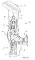
- FIG. 4 shows a third coupling part 17 with a device 5, according to FIG. 5 for an easy to establish mechanical connection with the device 1 the third coupling part 17 with the corresponding second Coupling part 12 of the upper joint part 3 is coupled.
- the second coupling part 12 of the upper joint part 3 with a first one Electric clutch 18 and the third coupling part 17 of the device 5 with one corresponding second electrical coupling 19 (indicated by dashed lines) Mistake.
- the piston 7 has a spring force setting device 20 (FIGS. 1 to 3 and 5) can be individually compensated for an excess weight of a device 5, preferably the spring force adjustment device 20 is provided with an adjusting screw 21 which is from the lower end of the lower Joint part 2 is adjustable with a tool, not shown.
- the cone 41 is shown, which has four slots 43 is provided and thus acts like a collet. On this cone 41 presses the spring 6. This creates a high level of friction between the screw 21 and the cone 41 generated. Because the screw 21 during the movement of the joint 2,3 is moved down towards the working position, prevents this friction, that the hinge 2, 3 suddenly falls into the working position with the device 5.
- the device 1 has a protective covering 22 with which the lower and the upper hinge part 2, 3 by means of a lower and an upper part overlapping spherical shell-like covering part 23.24 is protected, the preferably made of plastic.
- 20 shows further details to 27, wherein the lower trim part 23 in Figs. 20 to 23 and the upper Trim part 24 is shown in FIGS. 24 to 27, preferably each are manufactured as a one-piece plastic injection molded part.
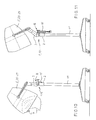
- a device 5 is a hair treatment device 25, for example one Hair dryer hood 26 or a steam hood 27 or a lamp 28, for example, an operating light 29 is provided (FIGS. 6 and 7).
- a PC monitor 30 is provided as device 5, for example a Flat screen (LCD) monitor 31, provided here in a low Position is set and has a table design as the support member 11.
- LCD Flat screen
- the monitor 30, 31 according to FIG. 12 is in a higher position set.
- the subject of the invention is a joint 2, 3 with two load-bearing joint parts 2, 3, which are rotatably connected by an axis X, a spring 5 via a piston 7, a screw 21 and a cone 41 are adjusted so that tilting around the X axis only after overcoming of a torque that results for each angular position.
- the Twist is limited by integrated stops.
- the Screw nut 40 arranged against rotation, making a very simple Torque fine adjustment via the screw 21 can be done from the outside.
Landscapes
- Cleaning And Drying Hair (AREA)
- Outer Garments And Coats (AREA)
- Ventilation (AREA)
- Pivots And Pivotal Connections (AREA)
- Dental Tools And Instruments Or Auxiliary Dental Instruments (AREA)
- Closing And Opening Devices For Wings, And Checks For Wings (AREA)
- Braking Arrangements (AREA)
- Transmission Devices (AREA)
Abstract
Description
- Fig. 1
- in einer Seitenschnittdarstellung eine Vorrichtung mit einem unteren und einem oberen Gelenkteil in einer Parkstellung;
- Fig. 2
- die Vorrichtung nach der Fig. 1, jedoch in einer Arbeitsstellung;
- Fig. 3
- in einer Schnittdarstellung die Vorrichtung nach Schnitt III-III der Fig.1;
- Fig. 4
- in einer Seitenansicht ein drittes Kupplungsteil eines Geräts;
- Fig. 5
- in einer Seitenansicht das dritte Kupplungsteil nach der Fig. 4 in einer Verkupplung mit der Vorrichtung nach der Fig. 1;
- Fig.6-9
- in verschiedenen Ansichten den vergrößert dargestellten Konus;
- Fig. 10
- in einer verkleinerten Seitenansicht die Vorrichtung mit einem Gerät und einem fahrbaren Tragelement in einer Arbeitsstellung;
- Fig. 11
- die Vorrichtung nach Fig. 10, das Gerät jedoch in einer Parkstellung;
- Fig. 12
- die Vorrichtung nach Fig. 10, jedoch mit einem Monitor und einem Tisch-Tragelement;
- Fig. 13
- die Vorrichtung nach Fig. 12, jedoch in einer Arbeitsstellung;
- Fig. 14-19
- in verschiedenen Ansichten das untere Gelenkteil ohne Komponenten;
- Fig. 20-23
- in verschiedenen Ansichten ein unteres Verkleidungsteil des unteren Gelenkteils;
- Fig. 24-27
- in verschiedenen Ansichten ein oberes Verkleidungsteil des oberen Gelenkteils, und
- Fig. 28-29
- eine erste und zweite Elektrokupplung.
- 1
- Vorrichtung
- 2
- Unteres Gelenkteil
- 3
- Oberes Gelenkteil
- 4
- Einrichtung (Übergewichtsausgleich)
- 5
- Gerät
- 6
- Druckfeder
- 7
- Kolben
- 8
- Kurventeil
- 9
- Kurvenverlauf
- 10
- Erstes Kupplungsteil
- 11
- Tragelement
- 12
- Zweites Kupplungsteil
- 13
- Baueinheit
- 14
- Kabeleinführung
- 15
- Kabel
- 16
- Kabelwickelaufnahme
- 17
- Drittes Kupplungsteil
- 18
- Erste Elektrokupplung
- 19
- Zweite Elektrokupplung
- 20
- Federkrafteinstelleinrichtung
- 21
- Stellschraube
- 22
- Schutzverkleidung
- 23
- Unteres Verkleidungsteil
- 24
- Oberes Verkleidungsteil
- 25
- Haarbehandlungsgerät
- 26
- Haartrockenhaube
- 27
- Dampfhaube
- 28
- Leuchte
- 29
- Operationsleuchte
- 30
- PC-Monitor
- 31
- Flachbildschirm-Monitor
- 40
- Mutter
- 41
- Konus
- 42
- Aufnahme
- 43
- Schlitz
- 44
- Gewinde
Claims (9)
- Vorrichtung (1) mit einem unteren und einem oberen Gelenkteil (2,3), wobei eine Einrichtung (4) zum Ausgleich eines Übergewichts eines von einer Arbeitsstellung in eine Parkstellung schwenkbaren Geräts (5) um eine waagrechte Achse (X) vorgesehen ist, dadurch gekennzeichnet, dass das untere Gelenkteil (2) mit einem Kolben (7) versehen ist, der durch eine Druckfeder (6) mit einem im oberen Gelenkteil (3) angeordneten Kurventeil (8) gleitend in Kraftschluss steht, wobei das Kurventeil (8) einen derartigen Kurvenverlauf (9) aufweist, dass ein stetiger Ausgleich des Übergewichts erfolgt, dass die Druckfeder (6) mittels einer Stellschraube (21) und einer drehfesten Mutter (40) vorgespannt ist und sich als Gegenlager auf einen Konus (41) abstützt, wobei der Konus (41) in einer dazu komplementären Aufnahme (42) am unteren Ende des unteren Gelenkteils (2) angeordnet ist, dass der Konus (41) derart mit Schlitzen (43) versehen ist, dass er wie eine Spannzange auf die Stellschraube (21) wirkt, die in diesem Bereich kein Gewinde (44) aufweist, dass das untere Gelenkteil (2) mit einem ersten Kupplungsteil (10) für ein Tragelement (11) und das obere Gelenkteil (3) mit einem zweiten Kupplungsteil (12) für das Gerät (5) versehen ist, und dass das untere und das obere Gelenkteil (2,3) als eine Baueinheit (13) ausgebildet ist.
- Vorrichtung nach Anspruch 1, dadurch gekennzeichnet, dass die Stellschraube (21) vom unteren Ende des unteren Gelenkteils (2) verstellbar ist.
- Vorrichtung nach Anspruch 1, dadurch gekennzeichnet, dass das untere Gelenkteil (2) mit einer Kabeleinführung (14) versehen ist.
- Vorrichtung nach Anspruch 1, dadurch gekennzeichnet, dass das untere Gelenkteil (2) mit einer Kabelwickelaufnahme (16) versehen ist.
- Vorrichtung nach Anspruch 1, dadurch gekennzeichnet, dass das Gerät (5) mit einem dritten Kupplungsteil (17) verbunden ist zum Verkuppeln mit dem dazu korrespondierenden zweiten Kupplungsteil (12) des oberen Gelenkteils (3).
- Vorrichtung nach mindestens Anspruch 5, dadurch gekennzeichnet, dass das zweite Kupplungsteil (12) des oberen Gelenkteils (3) mit einer ersten Elektrokupplung (18) und das dritte Kupplungsteil (17) des Geräts (5) mit einer dazu korrespondierenden zweiten Elektrokupplung (19) versehen ist.
- Vorrichtung nach mindestens Anspruch 1, dadurch gekennzeichnet, dass das erste und das zweite Gelenkteil (2,3) mit einer teilweise überlappenden kugelschalenartigen Schutzverkleidung (22) versehen ist.
- Vorrichtung nach mindestens Anspruch 7, dadurch gekennzeichnet, dass die Schutzverkleidung (22) aus Kunststoff besteht.
- Vorrichtung nach mindestens Anspruch 1, dadurch gekennzeichnet, dass als Gerät (5) ein Haarbehandlungsgerät (25), beispielsweise eine Haartrockenhaube (26) oder eine Dampfhaube (27) oder eine Leuchte (28), beispielsweise eine Operationsleuchte (29), oder ein PC-Monitor (30), beispielsweise ein Flachbildschirm-Monitor (31) vorgesehen ist.
Applications Claiming Priority (2)
| Application Number | Priority Date | Filing Date | Title |
|---|---|---|---|
| DE10033552 | 2000-07-11 | ||
| DE10033552 | 2000-07-11 |
Publications (3)
| Publication Number | Publication Date |
|---|---|
| EP1172044A2 true EP1172044A2 (de) | 2002-01-16 |
| EP1172044A3 EP1172044A3 (de) | 2004-11-03 |
| EP1172044B1 EP1172044B1 (de) | 2007-08-15 |
Family
ID=7648470
Family Applications (1)
| Application Number | Title | Priority Date | Filing Date |
|---|---|---|---|
| EP01116923A Expired - Lifetime EP1172044B1 (de) | 2000-07-11 | 2001-07-11 | Haartrockenhaube mit einer Vorrichtung zum Ausgleich eines Übergewichts |
Country Status (4)
| Country | Link |
|---|---|
| EP (1) | EP1172044B1 (de) |
| AT (1) | ATE369765T1 (de) |
| DE (2) | DE10133040A1 (de) |
| ES (1) | ES2291252T3 (de) |
Family Cites Families (9)
| Publication number | Priority date | Publication date | Assignee | Title |
|---|---|---|---|---|
| DE1073755B (de) * | 1960-01-21 | Sydenham London Naum Julius Slutzky (Großbritannien) | Einstellbare Stütze | |
| US2340185A (en) * | 1941-09-29 | 1944-01-25 | Harry L Waxman | Hair drier |
| DE1046847B (de) * | 1954-12-13 | 1958-12-18 | Kadus Werk Ludwig Kegel K G | Vorrichtung zum Ausgleichen des UEbergewichtes von frei auskragend gelagerten Geraeten oder Geraeteteilen, insbesondere fuer schwenkbare Haartrockenhauben |
| DE1059159B (de) * | 1958-06-25 | 1959-06-11 | Kadus Werk Ludwig Kegel K G | Vorrichtung zum Ausgleichen des UEbergewichtes von um eine waagerechte Achse schwenkbaren Geraeten, insbesondere fuer Haartrockenhauben |
| US3187374A (en) * | 1963-12-17 | 1965-06-08 | Weber Knapp Co | Hinge mechanism |
| US3683454A (en) * | 1969-11-20 | 1972-08-15 | Wilhelm Gronbach | Hinge assembly comprisin a compression spring for compensating the weight of wings |
| US5126928A (en) * | 1991-10-28 | 1992-06-30 | Charles Hughes | Mobile boom-mounted shop light |
| US5224675A (en) * | 1991-11-01 | 1993-07-06 | Pelco | Mounting apparatus |
| DE19822431C2 (de) * | 1998-05-19 | 2001-07-12 | Joachim Niehaus | Gelenkeinheit für Gestelle |
-
2001
- 2001-07-11 DE DE10133040A patent/DE10133040A1/de not_active Withdrawn
- 2001-07-11 ES ES01116923T patent/ES2291252T3/es not_active Expired - Lifetime
- 2001-07-11 AT AT01116923T patent/ATE369765T1/de not_active IP Right Cessation
- 2001-07-11 DE DE50112852T patent/DE50112852D1/de not_active Expired - Lifetime
- 2001-07-11 EP EP01116923A patent/EP1172044B1/de not_active Expired - Lifetime
Also Published As
| Publication number | Publication date |
|---|---|
| DE50112852D1 (de) | 2007-09-27 |
| EP1172044B1 (de) | 2007-08-15 |
| ATE369765T1 (de) | 2007-09-15 |
| EP1172044A3 (de) | 2004-11-03 |
| DE10133040A1 (de) | 2002-03-28 |
| ES2291252T3 (es) | 2008-03-01 |
Similar Documents
| Publication | Publication Date | Title |
|---|---|---|
| EP2873344B1 (de) | Möbel mit höhenverstellbarem Bein | |
| DE102014226645B4 (de) | Verstellmechanik zur Einstellung einer auf eine Rückenlehne eines Stuhls einwirkenden Rückstellkraft und Bürostuhl mit einer solchen Verstellmechanik | |
| DE202008017923U1 (de) | Operationsleuchte mit Aufhängevorrichtung | |
| DE202004016396U1 (de) | Dämpferanordnung | |
| EP0960304B1 (de) | Stativ mit einer in einem armrohr angeordneten druckfeder | |
| DE19817166B4 (de) | Schalthebelelement | |
| WO1998000688A1 (de) | Standfuss für eine messzelle | |
| DE3840893A1 (de) | Stehpult | |
| DE102005002838B4 (de) | Halterung für einen Videoprojektor | |
| DE102019115223B4 (de) | Presse | |
| EP1172044B1 (de) | Haartrockenhaube mit einer Vorrichtung zum Ausgleich eines Übergewichts | |
| AT17065U1 (de) | Beleuchtungsvorrichtung | |
| EP2787142A2 (de) | Freitragende Gelenkarm-Kassetten-Markise für Fahrzeuge | |
| CH692926A5 (de) | Stativ mit Energiespeicher zum Gewichtsausgleich. | |
| DE102007056232B4 (de) | Dreibeinstativ für die Vermessungstechnik | |
| EP2187118A1 (de) | Gelenkarm mit Drehgelenk | |
| DE10128382A1 (de) | Gehhilfe | |
| DE20218691U1 (de) | Stativ für ein Operationsmikroskop | |
| EP3408159A1 (de) | Lenksäule für ein kraftfahrzeug | |
| DE29616096U1 (de) | Höhenverstellbare Vorrichtung für Bildschirme | |
| DE19735331A1 (de) | Vorrichtung zur Aufnahme von Gegenständen | |
| DE4216371C2 (de) | Fußsteuervorrichtung für zahnärztliche Zwecke | |
| DE19541759A1 (de) | Höhenverstellbare Vorrichtung für Bildschirme | |
| DE20105914U1 (de) | Leuchte | |
| DE102010013146B4 (de) | Teleskopstativ |
Legal Events
| Date | Code | Title | Description |
|---|---|---|---|
| PUAI | Public reference made under article 153(3) epc to a published international application that has entered the european phase |
Free format text: ORIGINAL CODE: 0009012 |
|
| 17P | Request for examination filed |
Effective date: 20010720 |
|
| AK | Designated contracting states |
Kind code of ref document: A2 Designated state(s): AT BE CH CY DE DK ES FI FR GB GR IE IT LI LU MC NL PT SE TR |
|
| AX | Request for extension of the european patent |
Free format text: AL;LT;LV;MK;RO;SI |
|
| PUAL | Search report despatched |
Free format text: ORIGINAL CODE: 0009013 |
|
| AK | Designated contracting states |
Kind code of ref document: A3 Designated state(s): AT BE CH CY DE DK ES FI FR GB GR IE IT LI LU MC NL PT SE TR |
|
| AX | Request for extension of the european patent |
Extension state: AL LT LV MK RO SI |
|
| 17Q | First examination report despatched |
Effective date: 20041221 |
|
| AKX | Designation fees paid |
Designated state(s): AT BE CH CY DE DK ES FI FR GB GR IE IT LI LU MC NL PT SE TR |
|
| 17Q | First examination report despatched |
Effective date: 20041221 |
|
| GRAP | Despatch of communication of intention to grant a patent |
Free format text: ORIGINAL CODE: EPIDOSNIGR1 |
|
| RTI1 | Title (correction) |
Free format text: HAIR DRYER BONNET WITH A DEVICE FOR COMPENSATION OF A OVERWEIGHT |
|
| GRAS | Grant fee paid |
Free format text: ORIGINAL CODE: EPIDOSNIGR3 |
|
| GRAA | (expected) grant |
Free format text: ORIGINAL CODE: 0009210 |
|
| AK | Designated contracting states |
Kind code of ref document: B1 Designated state(s): AT BE CH CY DE DK ES FI FR GB GR IE IT LI LU MC NL PT SE TR |
|
| REG | Reference to a national code |
Ref country code: GB Ref legal event code: FG4D Free format text: NOT ENGLISH |
|
| REG | Reference to a national code |
Ref country code: CH Ref legal event code: EP |
|
| REG | Reference to a national code |
Ref country code: IE Ref legal event code: FG4D Free format text: LANGUAGE OF EP DOCUMENT: GERMAN |
|
| REF | Corresponds to: |
Ref document number: 50112852 Country of ref document: DE Date of ref document: 20070927 Kind code of ref document: P |
|
| GBT | Gb: translation of ep patent filed (gb section 77(6)(a)/1977) |
Effective date: 20070926 |
|
| REG | Reference to a national code |
Ref country code: SE Ref legal event code: TRGR |
|
| ET | Fr: translation filed | ||
| PG25 | Lapsed in a contracting state [announced via postgrant information from national office to epo] |
Ref country code: FI Free format text: LAPSE BECAUSE OF FAILURE TO SUBMIT A TRANSLATION OF THE DESCRIPTION OR TO PAY THE FEE WITHIN THE PRESCRIBED TIME-LIMIT Effective date: 20070815 Ref country code: NL Free format text: LAPSE BECAUSE OF FAILURE TO SUBMIT A TRANSLATION OF THE DESCRIPTION OR TO PAY THE FEE WITHIN THE PRESCRIBED TIME-LIMIT Effective date: 20070815 |
|
| NLV1 | Nl: lapsed or annulled due to failure to fulfill the requirements of art. 29p and 29m of the patents act | ||
| REG | Reference to a national code |
Ref country code: ES Ref legal event code: FG2A Ref document number: 2291252 Country of ref document: ES Kind code of ref document: T3 |
|
| REG | Reference to a national code |
Ref country code: IE Ref legal event code: FD4D |
|
| PG25 | Lapsed in a contracting state [announced via postgrant information from national office to epo] |
Ref country code: DK Free format text: LAPSE BECAUSE OF FAILURE TO SUBMIT A TRANSLATION OF THE DESCRIPTION OR TO PAY THE FEE WITHIN THE PRESCRIBED TIME-LIMIT Effective date: 20070815 Ref country code: GR Free format text: LAPSE BECAUSE OF FAILURE TO SUBMIT A TRANSLATION OF THE DESCRIPTION OR TO PAY THE FEE WITHIN THE PRESCRIBED TIME-LIMIT Effective date: 20071116 |
|
| PG25 | Lapsed in a contracting state [announced via postgrant information from national office to epo] |
Ref country code: IE Free format text: LAPSE BECAUSE OF FAILURE TO SUBMIT A TRANSLATION OF THE DESCRIPTION OR TO PAY THE FEE WITHIN THE PRESCRIBED TIME-LIMIT Effective date: 20070815 Ref country code: PT Free format text: LAPSE BECAUSE OF FAILURE TO SUBMIT A TRANSLATION OF THE DESCRIPTION OR TO PAY THE FEE WITHIN THE PRESCRIBED TIME-LIMIT Effective date: 20080115 |
|
| PLBE | No opposition filed within time limit |
Free format text: ORIGINAL CODE: 0009261 |
|
| STAA | Information on the status of an ep patent application or granted ep patent |
Free format text: STATUS: NO OPPOSITION FILED WITHIN TIME LIMIT |
|
| 26N | No opposition filed |
Effective date: 20080516 |
|
| REG | Reference to a national code |
Ref country code: CH Ref legal event code: PL |
|
| PG25 | Lapsed in a contracting state [announced via postgrant information from national office to epo] |
Ref country code: MC Free format text: LAPSE BECAUSE OF NON-PAYMENT OF DUE FEES Effective date: 20080731 |
|
| PG25 | Lapsed in a contracting state [announced via postgrant information from national office to epo] |
Ref country code: LI Free format text: LAPSE BECAUSE OF NON-PAYMENT OF DUE FEES Effective date: 20080731 Ref country code: CH Free format text: LAPSE BECAUSE OF NON-PAYMENT OF DUE FEES Effective date: 20080731 |
|
| PG25 | Lapsed in a contracting state [announced via postgrant information from national office to epo] |
Ref country code: CY Free format text: LAPSE BECAUSE OF FAILURE TO SUBMIT A TRANSLATION OF THE DESCRIPTION OR TO PAY THE FEE WITHIN THE PRESCRIBED TIME-LIMIT Effective date: 20070815 |
|
| PG25 | Lapsed in a contracting state [announced via postgrant information from national office to epo] |
Ref country code: AT Free format text: LAPSE BECAUSE OF NON-PAYMENT OF DUE FEES Effective date: 20080711 |
|
| PG25 | Lapsed in a contracting state [announced via postgrant information from national office to epo] |
Ref country code: BE Free format text: LAPSE BECAUSE OF NON-PAYMENT OF DUE FEES Effective date: 20080731 Ref country code: LU Free format text: LAPSE BECAUSE OF NON-PAYMENT OF DUE FEES Effective date: 20080711 |
|
| PG25 | Lapsed in a contracting state [announced via postgrant information from national office to epo] |
Ref country code: TR Free format text: LAPSE BECAUSE OF FAILURE TO SUBMIT A TRANSLATION OF THE DESCRIPTION OR TO PAY THE FEE WITHIN THE PRESCRIBED TIME-LIMIT Effective date: 20070815 |
|
| REG | Reference to a national code |
Ref country code: DE Ref legal event code: R081 Ref document number: 50112852 Country of ref document: DE Owner name: WELLA GMBH, DE Free format text: FORMER OWNER: WELLA AG, 64295 DARMSTADT, DE Effective date: 20110628 |
|
| REG | Reference to a national code |
Ref country code: ES Ref legal event code: PC2A Owner name: WELLA GMBH Effective date: 20120301 |
|
| REG | Reference to a national code |
Ref country code: FR Ref legal event code: CA Effective date: 20120906 Ref country code: FR Ref legal event code: CD Owner name: WELLA GMBH, DE Effective date: 20120906 |
|
| REG | Reference to a national code |
Ref country code: FR Ref legal event code: PLFP Year of fee payment: 15 |
|
| REG | Reference to a national code |
Ref country code: FR Ref legal event code: PLFP Year of fee payment: 16 |
|
| PGFP | Annual fee paid to national office [announced via postgrant information from national office to epo] |
Ref country code: IT Payment date: 20160720 Year of fee payment: 16 |
|
| PGFP | Annual fee paid to national office [announced via postgrant information from national office to epo] |
Ref country code: SE Payment date: 20160708 Year of fee payment: 16 |
|
| PGFP | Annual fee paid to national office [announced via postgrant information from national office to epo] |
Ref country code: ES Payment date: 20160708 Year of fee payment: 16 |
|
| REG | Reference to a national code |
Ref country code: FR Ref legal event code: PLFP Year of fee payment: 17 |
|
| REG | Reference to a national code |
Ref country code: SE Ref legal event code: EUG |
|
| PG25 | Lapsed in a contracting state [announced via postgrant information from national office to epo] |
Ref country code: SE Free format text: LAPSE BECAUSE OF NON-PAYMENT OF DUE FEES Effective date: 20170712 |
|
| PG25 | Lapsed in a contracting state [announced via postgrant information from national office to epo] |
Ref country code: IT Free format text: LAPSE BECAUSE OF NON-PAYMENT OF DUE FEES Effective date: 20170711 |
|
| REG | Reference to a national code |
Ref country code: ES Ref legal event code: FD2A Effective date: 20181024 |
|
| REG | Reference to a national code |
Ref country code: FR Ref legal event code: PLFP Year of fee payment: 18 |
|
| REG | Reference to a national code |
Ref country code: ES Ref legal event code: FD2A Effective date: 20181030 |
|
| PG25 | Lapsed in a contracting state [announced via postgrant information from national office to epo] |
Ref country code: ES Free format text: LAPSE BECAUSE OF NON-PAYMENT OF DUE FEES Effective date: 20170712 |
|
| PGFP | Annual fee paid to national office [announced via postgrant information from national office to epo] |
Ref country code: FR Payment date: 20190625 Year of fee payment: 19 |
|
| PGFP | Annual fee paid to national office [announced via postgrant information from national office to epo] |
Ref country code: DE Payment date: 20190620 Year of fee payment: 19 Ref country code: GB Payment date: 20190611 Year of fee payment: 19 |
|
| REG | Reference to a national code |
Ref country code: DE Ref legal event code: R119 Ref document number: 50112852 Country of ref document: DE |
|
| GBPC | Gb: european patent ceased through non-payment of renewal fee |
Effective date: 20200711 |
|
| PG25 | Lapsed in a contracting state [announced via postgrant information from national office to epo] |
Ref country code: GB Free format text: LAPSE BECAUSE OF NON-PAYMENT OF DUE FEES Effective date: 20200711 Ref country code: FR Free format text: LAPSE BECAUSE OF NON-PAYMENT OF DUE FEES Effective date: 20200731 |
|
| PG25 | Lapsed in a contracting state [announced via postgrant information from national office to epo] |
Ref country code: DE Free format text: LAPSE BECAUSE OF NON-PAYMENT OF DUE FEES Effective date: 20210202 |
|
| REG | Reference to a national code |
Ref country code: GB Ref legal event code: 732E Free format text: REGISTERED BETWEEN 20210617 AND 20210623 |
|
| REG | Reference to a national code |
Ref country code: GB Ref legal event code: 732E Free format text: REGISTERED BETWEEN 20210624 AND 20210630 |