EP1171353B1 - Verbesserte Indexierung von gärtnerischen Behältern - Google Patents
Verbesserte Indexierung von gärtnerischen Behältern Download PDFInfo
- Publication number
- EP1171353B1 EP1171353B1 EP99966790A EP99966790A EP1171353B1 EP 1171353 B1 EP1171353 B1 EP 1171353B1 EP 99966790 A EP99966790 A EP 99966790A EP 99966790 A EP99966790 A EP 99966790A EP 1171353 B1 EP1171353 B1 EP 1171353B1
- Authority
- EP
- European Patent Office
- Prior art keywords
- tray
- indexing
- cells
- rows
- receiving zones
- Prior art date
- Legal status (The legal status is an assumption and is not a legal conclusion. Google has not performed a legal analysis and makes no representation as to the accuracy of the status listed.)
- Expired - Lifetime
Links
- 239000000463 material Substances 0.000 claims abstract description 8
- 239000002991 molded plastic Substances 0.000 claims abstract description 3
- 230000000452 restraining effect Effects 0.000 claims description 10
- 230000002093 peripheral effect Effects 0.000 claims description 4
- 230000000295 complement effect Effects 0.000 claims 2
- 210000003141 lower extremity Anatomy 0.000 description 4
- 238000011109 contamination Methods 0.000 description 2
- 239000004794 expanded polystyrene Substances 0.000 description 2
- 238000000034 method Methods 0.000 description 2
- 230000001902 propagating effect Effects 0.000 description 2
- 238000010276 construction Methods 0.000 description 1
- 230000008602 contraction Effects 0.000 description 1
- 230000009977 dual effect Effects 0.000 description 1
- 230000000694 effects Effects 0.000 description 1
- 210000003414 extremity Anatomy 0.000 description 1
- 238000011068 loading method Methods 0.000 description 1
- 229920006395 saturated elastomer Polymers 0.000 description 1
- 239000002689 soil Substances 0.000 description 1
- 210000001364 upper extremity Anatomy 0.000 description 1
Images





Classifications
-
- B—PERFORMING OPERATIONS; TRANSPORTING
- B65—CONVEYING; PACKING; STORING; HANDLING THIN OR FILAMENTARY MATERIAL
- B65D—CONTAINERS FOR STORAGE OR TRANSPORT OF ARTICLES OR MATERIALS, e.g. BAGS, BARRELS, BOTTLES, BOXES, CANS, CARTONS, CRATES, DRUMS, JARS, TANKS, HOPPERS, FORWARDING CONTAINERS; ACCESSORIES, CLOSURES, OR FITTINGS THEREFOR; PACKAGING ELEMENTS; PACKAGES
- B65D1/00—Rigid or semi-rigid containers having bodies formed in one piece, e.g. by casting metallic material, by moulding plastics, by blowing vitreous material, by throwing ceramic material, by moulding pulped fibrous material or by deep-drawing operations performed on sheet material
- B65D1/34—Trays or like shallow containers
- B65D1/36—Trays or like shallow containers with moulded compartments or partitions
-
- A—HUMAN NECESSITIES
- A01—AGRICULTURE; FORESTRY; ANIMAL HUSBANDRY; HUNTING; TRAPPING; FISHING
- A01C—PLANTING; SOWING; FERTILISING
- A01C11/00—Transplanting machines
- A01C11/02—Transplanting machines for seedlings
- A01C11/025—Transplanting machines using seedling trays; Devices for removing the seedlings from the trays
-
- A—HUMAN NECESSITIES
- A01—AGRICULTURE; FORESTRY; ANIMAL HUSBANDRY; HUNTING; TRAPPING; FISHING
- A01G—HORTICULTURE; CULTIVATION OF VEGETABLES, FLOWERS, RICE, FRUIT, VINES, HOPS OR SEAWEED; FORESTRY; WATERING
- A01G9/00—Cultivation in receptacles, forcing-frames or greenhouses; Edging for beds, lawn or the like
- A01G9/02—Receptacles, e.g. flower-pots or boxes; Glasses for cultivating flowers
- A01G9/029—Receptacles for seedlings
- A01G9/0295—Units comprising two or more connected receptacles
Definitions
- the present invention relates to improvements in horticultural trays intended for indexing during seedling transfer processes, and indexing arrangements utilising such trays.
- This method when using thin walled light weight low cost cell construction allows the deflection of the lower extremity of the cell and thereby looses the accuracy necessary to correctly align a row of cells adjacent to a receiving mechanism. It has also been a widely used practice of utilising tapered cells with the ability to nest, that is the outside of an upper first tray to fit inside the upper surface of a lower second tray in the interest of conserving transport space and cost.
- indexing has been achieved on the ends or sides of the trays, which in certain field conditions are prone to the introduction of mud or contamination that can prevent indexing and in the case of indexing off the lower portion of the cells both contamination by mud and extraneous root materials can prevent correct indexing and location of the tray and intermittent jamming particularly when using low cost indexing means.
- the indexing mechanism may be positioned so as to prevent any deflection due to load and to provide precise indexing means. The location of the indexing to be in the most protected part of the tray structure to prevent entry of foreign materials which could cause jamming and inaccuracy of indexing.
- the present invention provides a moulded plastics material tray having a plurality of cells disposed in a predetermined array with each said cell being adapted to contain a seedling together with a plug of growing medium, said cells at least in an indexing region of said tray being aligned in rows between opposed edges of the tray with indexing engagement means integrally formed with said tray extending between two adjacent said rows of said cells, said tray being characterized in that said cells have thin walls and that said indexing means being configured to define a plurality of aligned and uniformly spaced indexing teeth receiving zones extending between said opposed edges of the tray with the indexing teeth receiving zones at least being located between two adjacent said rows of said cells on either side of the tray, a restraining member of said indexing engagement means extending between opposed said walls of respective said cells in each of the two adjacent said rows of said cells, the indexing teeth receiving zones being located between said restraining members.
- a said indexing teeth receiving zone is formed between an indexing teeth receiving zone.
- a flange region extending downwardly from an upper surface of each said tray towards the base region of each said tray is provided on at least two and preferably all four sides of the tray, the flange region having a lower edge surface adapted to rest on an upper peripheral edge surface of a similarly configured tray when the trays are nested one into the other.
- a cut out region extends through said flange region aligned with indexing teeth receiving zones in the indexing region of the tray.
- the indexing region or regions are necessarily located inwardly of the peripheral edges of the tray.
- the indexing region is located between the outermost row of cells and the next inwardly located row of cells. It is, however, possible to locate the indexing zone in other positions even further in from a peripheral edge of the tray.
- two indexing regions are provided laterally spaced on opposed sides of a tray.
- an indexing region may comprise two adjacent aligned rows of indexing teeth receiving zones. It is of course also possible to have three or more spaced indexing zones with at least one such indexing zone being located centrally of the tray.
- Each row of indexing teeth receiving zones are adapted, in use, to engage with teeth of an indexing wheel or disc of an indexing mechanism, the teeth being complimentary in shape to the indexing teeth receiving zones.
- the wheels or discs may be mounted on a common rotational shaft at at least one of the wheels or discs may be mounted for limited axial movement along the shaft to allow for minor differences in size of trays that might arise from differing thermal expansion rates or the like.
- FIG 1 A front side elevation view of the tray (12) is shown in FIG 1 .
- This view shows the upper support region (1) and the indexing engaging and restraining tooth (2) and the indexing disc tooth entry point (3) which are positioned on the outer extremities of the trays to give horizontal support and stability.
- FIG 2 shows an end elevation of the tray where the lower cells (4) are free to rest in the upper surface of the next tray without jamming due to a de-nesting edge (5).
- the end elevation view of FIG 2 is 90° displaced from the front side elevation view of FIG 1 .
- indexing restraining members (2) are shown in section which are attached directly and integrally with the underside of the upper surface (7) of the tray to protect against the entry of foreign matter including plant tops and in one preferred embodiment are situated between cells (6 & 8) ( FIG 4 ) which provides additional strength to the tray structure. This also does not interfere with tray nesting as the lower extremity of the tooth (2) is level with the underside of the de-nesting edge (5) and upper support region stiffening members.
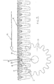
- FIG 5 An indexing disc or wheel (11) is illustrated in FIG 5 .
- the indexing disc (11) engages between the restraining teeth (2) and is controlled by an indexing mechanism (not shown). By this means a precise control is achieved of the indexed position of the tray. Indexing movements of the tray are achieved vertically in a preferred embodiment but this is not essential to the invention as horizontal indexing is also possible.
- FIG 6 illustrates engagement of a tapered indexing disc or wheel (11) entering between the lower extremity of the cells (6 & 8). The disc (11) rolls upwardly between the cells until it engages in the area of greatest structural integrity immediately on the under surface 30 adjacent to the apex of the upper extremity of the cells.
- This region also has the greatest structural integrity, and by this means, precise alignment of the tray cells laterally ( FIG 6 ) is achieved. If the direction of force acting on the tray (12) acts in the direction of arrow (10), then the force is restrained by the indexing disc (11) on the tooth faces at (19) and (20) providing a wide area of contact.
- FIG 6 is one embodiment of the invention which shows a single tray (12) engaged with the indexing discs (11) between the first and second cells (6, 8) at either end of the tray.
- one indexing disc will be fixed to the shaft (13) and by means of a slidable key or spline, the outer disc (11) may be allowed to move linearly to allow for tray expansion and contraction while maintaining tray alignment with the fixed indexing disc. It will of course be appreciated that the location of the discs 11 may be between other cell rows as desired.
- FIG 7 illustrates another embodiment which may be utilised in extreme application with heavy weight or high speed impact indexing with two or more indexing discs (11) fitted between the first, second and third rows of cells (8, 6 and 31) on both end regions of each tray or series of trays.
- FIG 8 an expanded view of the disc engaging region is shown in cross-section further illustrating the disc engaging and restraining member (2).
- This member (2) is supported between the cells (6 & 8) and attached to the upper surface and forms part of the underside of the upper portion of the tray (7) to restrain and prevent rotational forces exerted on the member (2) giving both structural integrity to the tray with greater stiffness and a very high degree of accuracy for indexing.
- FIG 9 illustrates another preferred embodiment where two or more trays (12a, 12b) are positioned adjacent to each other in a horizontal position with one or more engagement or indexing discs (11) positioned at either end region of the two or more trays with the discs being internally engaged inside the tray (12a, 12b).
- This arrangement allows for absolute accuracy of horizontal and vertical alignment of each tray which allows for precise indexing of horizontal rows of cells to be aligned with the receiving mechanism row to row horizontally across the tray and centre to centre of each row of cells, vertically across the tray and precisely the same from the last row of the last tray to the first row of a second tray both horizontally and vertically.
- the tapered alignment discs (11) also ensures that the trays (12a, 12b) and individual cells laterally dispersed across the width of the tray remain precisely on centre distances X cell (6a) to cell (8a) and tray to tray (cell 8a to 8b) with the centre distance of the cells X being equal both horizontally and vertically with the cell spacings the same on the last row of cells on the first tray to the centre of the first row of cells on the second tray.
- precise central alignment both in the vertical and horizontal of a multiple of trays (12, 12b) can be maintained with precise alignment with a receiving means for seedlings for high speed transfer of plugs / modules and plants from the tray into the receiving mechanism.
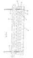
- FIG 10 shows inside elevation view channel tracks (14) that restrain the outer end of one, two or more trays (12). Where two or more trays are used, a central member (or members) 15 may be provided to restrain the inner edges of the trays 12. Again an indexing mechanism 17 including wheels 11 and a common shaft 13 are provided, the shaft 13 being indexed by a control system not shown.
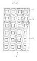
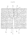
- FIG 11 shows a rear or underneath plan view of a tray (12) including cross supports (16), the upper support region (1), indexing and restraining tooth members (2), indexing teeth receiving zones (33), the indexing disc entry points (3), lower cells (4), a de-nesting edge (5), and the underside of the upper surface (7).
- the cross supports (16) are preferably the same height as the de-nesting edge (5).
- the indexing engagement means (2) extend in an aligned row fully between edges (34, 35) of the tray (12).
- FIG 12 shows two trays (12a) and (12b) each supported with twin indexing discs (11) at each end of each trays and providing horizontal support of two or any number of trays horizontally by means of a unified indexing assembly 21.
- the provision of a multiple number of trays allows for a greater number of plugs / modules to be transferred at one time to the mechanism for selectively transplanting. This factor increases the efficiency of a transplanting machine.
- the effect of multiples of trays horizontally and vertically increases the storage capacity of plugs / modules and plants and therefore reduces labour requirements for transplanting.
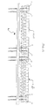
- FIG 13 shows a multiple of trays (12) from the rear elevation which are horizontally restrained by an indexing assembly 21 and by tray edge vertical restrains (14) and a tray to tray vertical edge restraint (15) as described in FIG 10 .
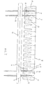
- FIG 14 shows a front elevation or top surface of trays (12) and the vertical tray edge restraints (14) and tray to tray restraint (15) as described in FIG 10 .
- the entry point at the top (24) of the tray edge restraints (14) and the top entry point (25) of the tray to tray vertical restraint (15) guide the descending plant stems into correct alignment in relation to the cell in which they are growing at the tray ends.
- Single or any number of multiples of trays (12) can be restrained and indexed in this manner.
- FIG 15 shows a part of a tray (12) engaged in the tray end vertical retainer (14) and the sloping entry point (24) which guides any misaligned plant stems into central position in cell (8).
- FIG 16 shows the vertical retainer (15) for trays (12a) to (12b) with dual sloping upper surfaces (25) to guide misaligned plant stems centrally into cells (8a) and (8b).
Landscapes
- Life Sciences & Earth Sciences (AREA)
- Environmental Sciences (AREA)
- Engineering & Computer Science (AREA)
- Soil Sciences (AREA)
- Ceramic Engineering (AREA)
- Mechanical Engineering (AREA)
- Cultivation Receptacles Or Flower-Pots, Or Pots For Seedlings (AREA)
Claims (15)
- Geformtes Kunststoffmaterialtablett (12) mit einer Mehrzahl von in einer vorbestimmten reihenförmigen Anordnung angeordneten Zellen (4, 6, 8), wobei jede Zelle (4, 6, 8) ausgelegt ist, einen Sämling zusammen mit einem Stopfen aus Wachstumsmedium zu enthalten, wobei die Zellen (4, 6, 8) zumindest in einem Indexierbereich des Tabletts in Reihen zwischen gegenüberliegenden Rändern (34, 35) des Tabletts (12) fluchten, wobei sich einstückig mit dem Tablett (12) ausgebildete Fortschalt-Eingriffsmittel (2) zwischen zwei benachbarten Reihen von Zellen (6, 8) erstrecken, dadurch gekennzeichnet, dass die Zellen (4, 6, 8) dünne Wände aufweisen und dass die Fortschalt-Mittel (2) so ausgestaltet sind, dass sie eine Mehrzahl von fluchtenden und einheitlich voneinander beabstandeten Zonen (33) zur Aufnahme von Schaltzähnen festlegen, welche Zonen sich zwischen den gegenüberliegenden Rändern (34, 35) der Tasse (12) erstrecken, wobei sich die Schaltzähne-Aufnahme-Zonen (33) zumindest zwischen zwei benachbarten Reihen von Zellen (6, 8) an jeder Seite des Tabletts (12) befinden, und wobei sich ein Rückhalteelement (2) der Fortschalt-Eingriffsmittel (2) zwischen gegenüberliegenden Wänden der entsprechenden Zellen in jeder der beiden benachbarten Reihen der Zellen (6, 8) erstreckt, wobei sich die Schaltzähne-Aufnahme-Zonen (33) zwischen den Rückhalteelementen (2) befinden.
- Tablett nach Anspruch 1, dadurch gekennzeichnet, dass keine Öffnungen von einer oberen Oberfläche des Tabletts zu einem Bereich zwischen den beiden benachbarten Reihen der Zellen (6, 8) verlaufen.
- Tablett nach Anspruch 1 oder 2, dadurch gekennzeichnet, dass das Tablett (12) in Draufsicht quadratisch oder rechteckig ist.
- Tablett nach Anspruch 3, dadurch gekennzeichnet, dass sich ein Flanschbereich (1) von einer oberen Fläche des Tabletts (12) an zumindest zwei gegenüberliegenden Seitenrandbereichen nach unten erstreckt.
- Tablett nach Anspruch 4, dadurch gekennzeichnet, dass sich der Flanschbereich (1) entlang aller vier Seitenrandbereiche des Tabletts (12) von der oberen Fläche nach unten erstreckt.
- Tablett nach Anspruch 4 oder 5, dadurch gekennzeichnet, dass die Flanschrandbereiche (1) eine untere Randfläche (5) aufweisen, die so ausgelegt ist, dass sie auf einer oberen Umfangsrandfläche eines ähnlich ausgestalteten Tabletts (12) aufliegt, wenn die Tabletts (12) ineinander gestapelt sind.
- Tablett nach einem der Ansprüche 4 bis 6, dadurch gekennzeichnet, dass sich ein Ausschnittbereich (3) durch gegenüberliegende Flanschbereiche (1) erstreckt, die mit Schaltzähne-Aufnahme-Zonen (33) im Indexier-Bereich des Tabletts (12) fluchten.
- Tablett nach Anspruch 1, dadurch gekennzeichnet, dass sich jede Reihe der Schaltzähne-Aufnahme-Zonen (33) an jeder Seite des Tabletts (12) zwischen den beiden äußersten benachbarten Reihen der Zellen (6, 8) befindet.
- Tablett nach Anspruch 1 oder Anspruch 8, dadurch gekennzeichnet, dass mindestens drei Reihen von Schaltzähne-Aufnahme-Zonen (33) voneinander beabstandet quer über das Tablett (12) angeordnet sind.
- Tablett nach Anspruch 1, dadurch gekennzeichnet, dass ein Paar Reihen von Schaltzähne-Aufnahme-Zonen (33) zwischen drei benachbarten Reihen der Zellen (6, 8) an jeder Seite des Tabletts (12) vorgesehen sind.
- Tablett nach einem der Ansprüche 1 bis 10 in Kombination mit einem Tablett-Zuführmittel (14, 15) und einer Indexieranordnung (21), welche Kombination dadurch gekennzeichnet ist, dass das Tablett-Zuführmittel (14, 15) den Tablettrand stützende Führungen (14, 15) aufweist, die es dem Tablett (12) ermöglichen, sich daran entlang zu bewegen, und die Inexieranordnung (21) eine Antriebswelle (13) aufweist, die eine Schaltscheibe (11) trägt für jede fluchtende Gruppe der Schaltzähne-Aufnahme-Zonen (33) an dem Tablett (12), wobei die oder jede Schaltscheibe (11) Zähne aufweist, deren Form komplementär zu den Schaltzähne-Aufnahme-Zonen (33) ist.
- Kombination nach Anspruch 11, dadurch gekennzeichnet, dass alle Schaltscheiben (11) für ein Tablett (12) drehfest in Bezug auf die Antriebswelle (13) sind, wobei eine erste der Schaltscheiben (11) in Bezug auf die Antriebswelle (13) auch axial fixiert ist, und wobei alle anderen Schaltscheiben (11) in Bezug auf die Antriebswelle (13) axial beweglich sind.
- Kombination nach Anspruch 11 oder 12, dadurch gekennzeichnet, dass axiale Flächen (19, 20) der Zähne zu ihrem äußersten Punkt hin verjüngt sind, wobei die axialen Flächen (19, 20) und die Umfangsflächen der Zähne in der Form komplementär zu den Schaltzähne-Aufnahme-Zonen (33) sind.
- Kombination nach einem der Ansprüche 11 bis 13, dadurch gekennzeichnet, dass das Tablett-Zuführmittel (14, 15) ermöglicht, dass zumindest zwei der Tabletts (12) in Seite-an-Seite- Konfiguration zugeführt werden.
- Kombination nach einem der Ansprüche 11 bis 14, wobei die den Tablettrand stützenden Führungen (14, 15) Einführungs-Rampenoberflächen enthalten, die so angeordnet sind, dass sie Stiel- und Blattmaterial der Sämlinge zur Innenseite des Tabletts (12) drängen.
Applications Claiming Priority (3)
| Application Number | Priority Date | Filing Date | Title |
|---|---|---|---|
| AUPP7924A AUPP792498A0 (en) | 1998-12-24 | 1998-12-24 | Improved indexing of horticultural trays |
| AUPP792498 | 1998-12-24 | ||
| PCT/AU1999/001151 WO2000038996A1 (en) | 1998-12-24 | 1999-12-22 | Improved indexing of horticultural trays |
Publications (3)
| Publication Number | Publication Date |
|---|---|
| EP1171353A1 EP1171353A1 (de) | 2002-01-16 |
| EP1171353A4 EP1171353A4 (de) | 2006-08-09 |
| EP1171353B1 true EP1171353B1 (de) | 2008-08-13 |
Family
ID=3812131
Family Applications (1)
| Application Number | Title | Priority Date | Filing Date |
|---|---|---|---|
| EP99966790A Expired - Lifetime EP1171353B1 (de) | 1998-12-24 | 1999-12-22 | Verbesserte Indexierung von gärtnerischen Behältern |
Country Status (7)
| Country | Link |
|---|---|
| EP (1) | EP1171353B1 (de) |
| AT (1) | ATE404441T1 (de) |
| AU (1) | AUPP792498A0 (de) |
| DE (1) | DE69939338D1 (de) |
| ES (1) | ES2312224T3 (de) |
| NZ (1) | NZ512591A (de) |
| WO (1) | WO2000038996A1 (de) |
Cited By (3)
| Publication number | Priority date | Publication date | Assignee | Title |
|---|---|---|---|---|
| CN106134837A (zh) * | 2016-07-12 | 2016-11-23 | 秦广泉 | 一种水稻钵苗机及其使用的育秧盘 |
| CN106856757A (zh) * | 2017-04-07 | 2017-06-20 | 湖南农业大学 | 一种钵苗脱盘装置 |
| CN106973600A (zh) * | 2017-04-07 | 2017-07-25 | 湖南农业大学 | 一种钵苗取苗送苗装置 |
Families Citing this family (5)
| Publication number | Priority date | Publication date | Assignee | Title |
|---|---|---|---|---|
| CN102057785B (zh) * | 2010-11-05 | 2012-07-04 | 东北农业大学 | 旱田钵苗移栽机用育秧盘 |
| FI125975B (fi) | 2014-10-31 | 2016-05-13 | Risutec Oy | Menetelmä taimien istutuskoneessa ja taimien istutuskone |
| AU2017265108B2 (en) * | 2016-11-23 | 2024-03-07 | Williames Pty Ltd | Improvements to nursery trays for automation |
| CN110431967A (zh) * | 2019-08-29 | 2019-11-12 | 贵州大学 | 一种农业种植作业用均苗布设平台 |
| WO2021138206A2 (en) * | 2019-12-31 | 2021-07-08 | Monterey Mushrooms, Inc. | Mushroom harvesting container funnel tray and sorting device |
Family Cites Families (3)
| Publication number | Priority date | Publication date | Assignee | Title |
|---|---|---|---|---|
| WO1995004451A1 (en) * | 1993-08-04 | 1995-02-16 | Speedling, Inc. | A transplanter for seedlings |
| JP3434390B2 (ja) * | 1995-06-28 | 2003-08-04 | ヤンマー農機株式会社 | 苗移植機 |
| AUPO223196A0 (en) * | 1996-09-11 | 1996-10-03 | Williames Hi-Tech International Pty Ltd | Improved nursery trays and handling mechanisms therefor |
-
1998
- 1998-12-24 AU AUPP7924A patent/AUPP792498A0/en not_active Abandoned
-
1999
- 1999-12-22 AT AT99966790T patent/ATE404441T1/de not_active IP Right Cessation
- 1999-12-22 WO PCT/AU1999/001151 patent/WO2000038996A1/en not_active Ceased
- 1999-12-22 EP EP99966790A patent/EP1171353B1/de not_active Expired - Lifetime
- 1999-12-22 DE DE69939338T patent/DE69939338D1/de not_active Expired - Lifetime
- 1999-12-22 NZ NZ512591A patent/NZ512591A/xx not_active IP Right Cessation
- 1999-12-22 ES ES99966790T patent/ES2312224T3/es not_active Expired - Lifetime
Cited By (5)
| Publication number | Priority date | Publication date | Assignee | Title |
|---|---|---|---|---|
| CN106134837A (zh) * | 2016-07-12 | 2016-11-23 | 秦广泉 | 一种水稻钵苗机及其使用的育秧盘 |
| CN106856757A (zh) * | 2017-04-07 | 2017-06-20 | 湖南农业大学 | 一种钵苗脱盘装置 |
| CN106973600A (zh) * | 2017-04-07 | 2017-07-25 | 湖南农业大学 | 一种钵苗取苗送苗装置 |
| CN106973600B (zh) * | 2017-04-07 | 2018-05-08 | 湖南农业大学 | 一种钵苗取苗送苗装置 |
| CN106856757B (zh) * | 2017-04-07 | 2018-06-29 | 湖南农业大学 | 一种钵苗脱盘装置 |
Also Published As
| Publication number | Publication date |
|---|---|
| ES2312224T3 (es) | 2009-02-16 |
| EP1171353A1 (de) | 2002-01-16 |
| DE69939338D1 (de) | 2008-09-25 |
| NZ512591A (en) | 2002-12-20 |
| WO2000038996A1 (en) | 2000-07-06 |
| ATE404441T1 (de) | 2008-08-15 |
| EP1171353A4 (de) | 2006-08-09 |
| AUPP792498A0 (en) | 1999-01-28 |
Similar Documents
| Publication | Publication Date | Title |
|---|---|---|
| EP1019292B1 (de) | Verbesserte sämlingschalen und behandlungsmechanismus hierfür | |
| US5022183A (en) | Flower pot carrying tray with restraining means for plural pots | |
| US6085462A (en) | Molded plant tray | |
| EP1171353A1 (de) | Verbesserte Indexierung von gärtnerischen Behältern | |
| US8579574B2 (en) | Storage rack with a multiplicity of rack units | |
| FI63152C (fi) | Saett vid odling av plantor jaemte anordning foer utfoerande av saettet | |
| US20160096680A1 (en) | Tray for transporting horticultural containers | |
| US4982527A (en) | Seedling propagation assembly | |
| CA2279010A1 (en) | Cell and cell tray for growing seedlings | |
| CA2142119A1 (en) | Apparatus for automatically planting seedings taken from a hard seedling tray | |
| US3945883A (en) | Liquid metal cooled nuclear reactors | |
| EP2975925B1 (de) | Doppelablagesystem für aussaat oder umpflanzen von sämlingen | |
| AU755183B2 (en) | Improved indexing of horticultural trays | |
| CA1222484A (en) | Egg holding flat | |
| US6385903B1 (en) | Plug tray | |
| GB1444398A (en) | Egg incubating tray | |
| DE69204581D1 (de) | Stapeln von Gegenständen zur Lagerung und/oder zum Transit. | |
| US6085460A (en) | System for holding plant containers | |
| EP1733614B1 (de) | Mehrfach-Schienen-System und Verfahren zum Züchten eines Gewächses in einer Anbauwanne und Gärtnerei mit einer solchen | |
| US3818634A (en) | Tray | |
| US6142774A (en) | Support for a ceramic wagon superstructure for supporting molded blanks of ceramic material to be fired | |
| FI88351B (fi) | Anordning foer transport av tomma odlingsraennor i en vaextodlingsanlaeggning | |
| EP0255864A2 (de) | Tablett mit eingeformter Aufteilung für Kiwi-Früchte | |
| KR200170456Y1 (ko) | 재배용 패널 | |
| WO2019172816A1 (en) | Plant cell support |
Legal Events
| Date | Code | Title | Description |
|---|---|---|---|
| PUAI | Public reference made under article 153(3) epc to a published international application that has entered the european phase |
Free format text: ORIGINAL CODE: 0009012 |
|
| 17P | Request for examination filed |
Effective date: 20010724 |
|
| AK | Designated contracting states |
Kind code of ref document: A1 Designated state(s): AT BE CH CY DE DK ES FI FR GB GR IE IT LI LU MC NL PT SE |
|
| A4 | Supplementary search report drawn up and despatched |
Effective date: 20060706 |
|
| 17Q | First examination report despatched |
Effective date: 20070103 |
|
| GRAP | Despatch of communication of intention to grant a patent |
Free format text: ORIGINAL CODE: EPIDOSNIGR1 |
|
| RTI1 | Title (correction) |
Free format text: IMPROVED INDEXING OF HORTICULTURAL TRAYS |
|
| GRAS | Grant fee paid |
Free format text: ORIGINAL CODE: EPIDOSNIGR3 |
|
| GRAA | (expected) grant |
Free format text: ORIGINAL CODE: 0009210 |
|
| AK | Designated contracting states |
Kind code of ref document: B1 Designated state(s): AT BE CH CY DE DK ES FI FR GB GR IE IT LI LU MC NL PT SE |
|
| REG | Reference to a national code |
Ref country code: GB Ref legal event code: FG4D |
|
| REG | Reference to a national code |
Ref country code: CH Ref legal event code: EP |
|
| RAP2 | Party data changed (patent owner data changed or rights of a patent transferred) |
Owner name: WILLIAMES PTY LTD. |
|
| REG | Reference to a national code |
Ref country code: IE Ref legal event code: FG4D |
|
| REF | Corresponds to: |
Ref document number: 69939338 Country of ref document: DE Date of ref document: 20080925 Kind code of ref document: P |
|
| NLT2 | Nl: modifications (of names), taken from the european patent patent bulletin |
Owner name: WILLIAMES PTY LTD. Effective date: 20080903 |
|
| REG | Reference to a national code |
Ref country code: ES Ref legal event code: FG2A Ref document number: 2312224 Country of ref document: ES Kind code of ref document: T3 |
|
| PG25 | Lapsed in a contracting state [announced via postgrant information from national office to epo] |
Ref country code: FI Free format text: LAPSE BECAUSE OF FAILURE TO SUBMIT A TRANSLATION OF THE DESCRIPTION OR TO PAY THE FEE WITHIN THE PRESCRIBED TIME-LIMIT Effective date: 20080813 Ref country code: AT Free format text: LAPSE BECAUSE OF FAILURE TO SUBMIT A TRANSLATION OF THE DESCRIPTION OR TO PAY THE FEE WITHIN THE PRESCRIBED TIME-LIMIT Effective date: 20080813 |
|
| PG25 | Lapsed in a contracting state [announced via postgrant information from national office to epo] |
Ref country code: DK Free format text: LAPSE BECAUSE OF FAILURE TO SUBMIT A TRANSLATION OF THE DESCRIPTION OR TO PAY THE FEE WITHIN THE PRESCRIBED TIME-LIMIT Effective date: 20080813 |
|
| PG25 | Lapsed in a contracting state [announced via postgrant information from national office to epo] |
Ref country code: PT Free format text: LAPSE BECAUSE OF FAILURE TO SUBMIT A TRANSLATION OF THE DESCRIPTION OR TO PAY THE FEE WITHIN THE PRESCRIBED TIME-LIMIT Effective date: 20090113 |
|
| PLBE | No opposition filed within time limit |
Free format text: ORIGINAL CODE: 0009261 |
|
| STAA | Information on the status of an ep patent application or granted ep patent |
Free format text: STATUS: NO OPPOSITION FILED WITHIN TIME LIMIT |
|
| 26N | No opposition filed |
Effective date: 20090514 |
|
| PG25 | Lapsed in a contracting state [announced via postgrant information from national office to epo] |
Ref country code: MC Free format text: LAPSE BECAUSE OF NON-PAYMENT OF DUE FEES Effective date: 20081231 |
|
| REG | Reference to a national code |
Ref country code: CH Ref legal event code: PL |
|
| REG | Reference to a national code |
Ref country code: IE Ref legal event code: MM4A |
|
| PG25 | Lapsed in a contracting state [announced via postgrant information from national office to epo] |
Ref country code: LI Free format text: LAPSE BECAUSE OF NON-PAYMENT OF DUE FEES Effective date: 20081231 Ref country code: IE Free format text: LAPSE BECAUSE OF NON-PAYMENT OF DUE FEES Effective date: 20081222 Ref country code: CH Free format text: LAPSE BECAUSE OF NON-PAYMENT OF DUE FEES Effective date: 20081231 |
|
| PG25 | Lapsed in a contracting state [announced via postgrant information from national office to epo] |
Ref country code: SE Free format text: LAPSE BECAUSE OF FAILURE TO SUBMIT A TRANSLATION OF THE DESCRIPTION OR TO PAY THE FEE WITHIN THE PRESCRIBED TIME-LIMIT Effective date: 20081113 |
|
| PGFP | Annual fee paid to national office [announced via postgrant information from national office to epo] |
Ref country code: NL Payment date: 20091224 Year of fee payment: 11 |
|
| PGFP | Annual fee paid to national office [announced via postgrant information from national office to epo] |
Ref country code: IT Payment date: 20091222 Year of fee payment: 11 |
|
| PGFP | Annual fee paid to national office [announced via postgrant information from national office to epo] |
Ref country code: FR Payment date: 20100112 Year of fee payment: 11 |
|
| PGFP | Annual fee paid to national office [announced via postgrant information from national office to epo] |
Ref country code: DE Payment date: 20091222 Year of fee payment: 11 Ref country code: BE Payment date: 20100212 Year of fee payment: 11 |
|
| PG25 | Lapsed in a contracting state [announced via postgrant information from national office to epo] |
Ref country code: LU Free format text: LAPSE BECAUSE OF NON-PAYMENT OF DUE FEES Effective date: 20081222 Ref country code: CY Free format text: LAPSE BECAUSE OF FAILURE TO SUBMIT A TRANSLATION OF THE DESCRIPTION OR TO PAY THE FEE WITHIN THE PRESCRIBED TIME-LIMIT Effective date: 20080813 |
|
| PG25 | Lapsed in a contracting state [announced via postgrant information from national office to epo] |
Ref country code: GR Free format text: LAPSE BECAUSE OF FAILURE TO SUBMIT A TRANSLATION OF THE DESCRIPTION OR TO PAY THE FEE WITHIN THE PRESCRIBED TIME-LIMIT Effective date: 20081114 |
|
| PGFP | Annual fee paid to national office [announced via postgrant information from national office to epo] |
Ref country code: GB Payment date: 20101230 Year of fee payment: 12 |
|
| BERE | Be: lapsed |
Owner name: WILLIAMES HI-TECH INTERNATIONAL PTY. LTD Effective date: 20101231 |
|
| REG | Reference to a national code |
Ref country code: NL Ref legal event code: V1 Effective date: 20110701 |
|
| PGFP | Annual fee paid to national office [announced via postgrant information from national office to epo] |
Ref country code: ES Payment date: 20110125 Year of fee payment: 12 |
|
| REG | Reference to a national code |
Ref country code: FR Ref legal event code: ST Effective date: 20110831 |
|
| PG25 | Lapsed in a contracting state [announced via postgrant information from national office to epo] |
Ref country code: BE Free format text: LAPSE BECAUSE OF NON-PAYMENT OF DUE FEES Effective date: 20101231 |
|
| PG25 | Lapsed in a contracting state [announced via postgrant information from national office to epo] |
Ref country code: FR Free format text: LAPSE BECAUSE OF NON-PAYMENT OF DUE FEES Effective date: 20110103 |
|
| REG | Reference to a national code |
Ref country code: DE Ref legal event code: R119 Ref document number: 69939338 Country of ref document: DE Effective date: 20110701 |
|
| PG25 | Lapsed in a contracting state [announced via postgrant information from national office to epo] |
Ref country code: DE Free format text: LAPSE BECAUSE OF NON-PAYMENT OF DUE FEES Effective date: 20110701 |
|
| PG25 | Lapsed in a contracting state [announced via postgrant information from national office to epo] |
Ref country code: IT Free format text: LAPSE BECAUSE OF NON-PAYMENT OF DUE FEES Effective date: 20101222 Ref country code: NL Free format text: LAPSE BECAUSE OF NON-PAYMENT OF DUE FEES Effective date: 20110701 |
|
| GBPC | Gb: european patent ceased through non-payment of renewal fee |
Effective date: 20111222 |
|
| PG25 | Lapsed in a contracting state [announced via postgrant information from national office to epo] |
Ref country code: GB Free format text: LAPSE BECAUSE OF NON-PAYMENT OF DUE FEES Effective date: 20111222 |
|
| REG | Reference to a national code |
Ref country code: ES Ref legal event code: FD2A Effective date: 20130703 |
|
| PG25 | Lapsed in a contracting state [announced via postgrant information from national office to epo] |
Ref country code: ES Free format text: LAPSE BECAUSE OF NON-PAYMENT OF DUE FEES Effective date: 20111223 |