EP1171187B1 - Apparatus for reducing fluid drawback through a medical valve - Google Patents
Apparatus for reducing fluid drawback through a medical valve Download PDFInfo
- Publication number
- EP1171187B1 EP1171187B1 EP00903148A EP00903148A EP1171187B1 EP 1171187 B1 EP1171187 B1 EP 1171187B1 EP 00903148 A EP00903148 A EP 00903148A EP 00903148 A EP00903148 A EP 00903148A EP 1171187 B1 EP1171187 B1 EP 1171187B1
- Authority
- EP
- European Patent Office
- Prior art keywords
- valve
- chamber
- compressible member
- fluid
- medical valve
- Prior art date
- Legal status (The legal status is an assumption and is not a legal conclusion. Google has not performed a legal analysis and makes no representation as to the accuracy of the status listed.)
- Expired - Lifetime
Links
- 239000012530 fluid Substances 0.000 title claims abstract description 40
- 239000007788 liquid Substances 0.000 claims description 13
- 239000000463 material Substances 0.000 claims description 8
- 238000004891 communication Methods 0.000 claims description 2
- 230000007704 transition Effects 0.000 claims 1
- 210000004907 gland Anatomy 0.000 description 7
- 239000008280 blood Substances 0.000 description 4
- 210000004369 blood Anatomy 0.000 description 4
- 229920001971 elastomer Polymers 0.000 description 3
- 238000013022 venting Methods 0.000 description 3
- 230000006837 decompression Effects 0.000 description 2
- 229920000126 latex Polymers 0.000 description 2
- 239000004816 latex Substances 0.000 description 2
- 230000007246 mechanism Effects 0.000 description 2
- 238000012986 modification Methods 0.000 description 2
- 230000004048 modification Effects 0.000 description 2
- 210000005166 vasculature Anatomy 0.000 description 2
- IJGRMHOSHXDMSA-UHFFFAOYSA-N Atomic nitrogen Chemical compound N#N IJGRMHOSHXDMSA-UHFFFAOYSA-N 0.000 description 1
- 230000003466 anti-cipated effect Effects 0.000 description 1
- 230000036772 blood pressure Effects 0.000 description 1
- 230000001112 coagulating effect Effects 0.000 description 1
- 230000006835 compression Effects 0.000 description 1
- 238000007906 compression Methods 0.000 description 1
- 239000000356 contaminant Substances 0.000 description 1
- 230000008878 coupling Effects 0.000 description 1
- 238000010168 coupling process Methods 0.000 description 1
- 238000005859 coupling reaction Methods 0.000 description 1
- 230000007423 decrease Effects 0.000 description 1
- 230000003247 decreasing effect Effects 0.000 description 1
- 229910001873 dinitrogen Inorganic materials 0.000 description 1
- 229940079593 drug Drugs 0.000 description 1
- 239000003814 drug Substances 0.000 description 1
- 230000009977 dual effect Effects 0.000 description 1
- 239000000806 elastomer Substances 0.000 description 1
- 239000013536 elastomeric material Substances 0.000 description 1
- 230000036512 infertility Effects 0.000 description 1
- 238000002347 injection Methods 0.000 description 1
- 239000007924 injection Substances 0.000 description 1
- 238000001746 injection moulding Methods 0.000 description 1
- 238000003780 insertion Methods 0.000 description 1
- 230000037431 insertion Effects 0.000 description 1
- 230000013011 mating Effects 0.000 description 1
- 229940127554 medical product Drugs 0.000 description 1
- 239000004033 plastic Substances 0.000 description 1
- 229920003023 plastic Polymers 0.000 description 1
- 229920000728 polyester Polymers 0.000 description 1
- 229920001296 polysiloxane Polymers 0.000 description 1
- 230000004044 response Effects 0.000 description 1
- 230000002792 vascular Effects 0.000 description 1
Images


Classifications
-
- A—HUMAN NECESSITIES
- A61—MEDICAL OR VETERINARY SCIENCE; HYGIENE
- A61M—DEVICES FOR INTRODUCING MEDIA INTO, OR ONTO, THE BODY; DEVICES FOR TRANSDUCING BODY MEDIA OR FOR TAKING MEDIA FROM THE BODY; DEVICES FOR PRODUCING OR ENDING SLEEP OR STUPOR
- A61M39/00—Tubes, tube connectors, tube couplings, valves, access sites or the like, specially adapted for medical use
- A61M39/22—Valves or arrangement of valves
- A61M39/26—Valves closing automatically on disconnecting the line and opening on reconnection thereof
- A61M2039/263—Valves closing automatically on disconnecting the line and opening on reconnection thereof where the fluid space within the valve is decreasing upon disconnection
-
- A—HUMAN NECESSITIES
- A61—MEDICAL OR VETERINARY SCIENCE; HYGIENE
- A61M—DEVICES FOR INTRODUCING MEDIA INTO, OR ONTO, THE BODY; DEVICES FOR TRANSDUCING BODY MEDIA OR FOR TAKING MEDIA FROM THE BODY; DEVICES FOR PRODUCING OR ENDING SLEEP OR STUPOR
- A61M39/00—Tubes, tube connectors, tube couplings, valves, access sites or the like, specially adapted for medical use
- A61M39/22—Valves or arrangement of valves
- A61M39/26—Valves closing automatically on disconnecting the line and opening on reconnection thereof
- A61M2039/266—Valves closing automatically on disconnecting the line and opening on reconnection thereof where the valve comprises venting channels, e.g. to insure better connection, to help decreasing the fluid space upon disconnection, or to help the fluid space to remain the same during disconnection
-
- A—HUMAN NECESSITIES
- A61—MEDICAL OR VETERINARY SCIENCE; HYGIENE
- A61M—DEVICES FOR INTRODUCING MEDIA INTO, OR ONTO, THE BODY; DEVICES FOR TRANSDUCING BODY MEDIA OR FOR TAKING MEDIA FROM THE BODY; DEVICES FOR PRODUCING OR ENDING SLEEP OR STUPOR
- A61M39/00—Tubes, tube connectors, tube couplings, valves, access sites or the like, specially adapted for medical use
- A61M39/22—Valves or arrangement of valves
- A61M39/26—Valves closing automatically on disconnecting the line and opening on reconnection thereof
- A61M2039/267—Valves closing automatically on disconnecting the line and opening on reconnection thereof having a sealing sleeve around a tubular or solid stem portion of the connector
Definitions
- the invention generally relates to medical products and, more particularly, the invention relates to devices for reducing backflow through a medical valve.
- Medical valving devices commonly are utilized to valve fluids injected into and withdrawn from a patient.
- One exemplary type of medical valving device known in the art as a"catheter introducer,"maintains a sealed port for accessing the patient's vasculature. Use of such a valve enables vascular access without requiring the patient's skin to be repeatedly pierced by a needle.
- catheter introducers are constructed to withstand a range of back-pressures produced by a patient's blood pressure, thus minimizing blood loss resulting from fluid injections or withdrawals.
- Fluid commonly is transferred to/from a patient by inserting a syringe (e. g., a needle) into a medical valve, thus communicating with the patient's vasculature.
- a syringe e. g., a needle
- problems arise, however, when the syringe is withdrawn from the valve. More particularly, a back pressure produced by withdrawing the syringe undesirably can cause blood to leak proximal into various parts of the valve.
- blood in the valve also compromises the sterility of the valve.
- GB 2079162 describes a resuscitator valve having a spring loaded relief valve within an interior chamber.
- US 3192949 describes a spring biased check valve having a resilient body within the chamber to urge a moveable valve element against a seal.
- US 5401255 describes a control valve incorporating a one-way valve formed of elastrometric material.
- a medical valve for valving fluid is as defined in claim 1.
- the compressible member does not occlude fluid flow through the fluid channel.
- the compressible member may be any compressible object that is made from any compressible material known in the art.
- the compressible member may be made from a sponge material.
- the compressible member also may be made from a material that merely expands and contracts in response to a mechanical force.
- the compressible member may be a balloon device.
- the medical valve also may include a plunger, having a distal end within the interior, that controls the volume of the variable volume interior.
- the valve is movable between open and closed positions.
- the compressible member may cooperate with the interior to cause the interior to have a greater available volume (for containing fluid) when the valve is open than when the valve is closed. Accordingly, as the valve closes (and the available volume decreases), residual fluid within the valve should be forced from the chamber toward the outlet of the valve.
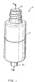
- FIG 1 schematically shows a medical valve 5 that preferably is configured to reduce fluid drawback (a/k/a "back-flow") when a syringe or other type of nozzle is withdrawn from it.
- the valve 5 includes a proximal fluid port 10 for receiving the nozzle, a valve body 11 having a valving mechanism (figures 2 and 3A-3D) that controls fluid flow through the valve 5, and a distally located fluid port 50 for directing fluid between the valve 5 and a patient.
- the fluid preferably is in liqui'd form, such as liquid medication.
- the proximal port 10 as a fluid inlet
- the distal port 50 as a fluid outlet
- the proximal and distal ports 10 and 50 also may be utilized respectively as outlet and inlet ports.
- the valve 5 is similar to that disclosed in WO 98/22178 entitled, "SWABBABLE LUER-ACTIVATED VALVE, " naming Andrew Cote and Charles Ganem as inventors. It should be noted that although preferred embodiments are discussed with reference to the above noted patent application, principles of the invention may be applied to other medical valve devices having dissimilar structures to those medical valves shown. As discussed below, the distal port 50 of the valve 5 may be at its location shown in figure 1, or at a location that is orthogonal to the longitudinal dimension of the valve 5.
- FIG. 2 schematically shows a cross-sectional view of a first embodiment of the medical valve 5 shown in figure I along line 2-2.
- the valve 5 includes an inlet housing portion 34 having the proximal port 10, an outlet housing portion 48 having the distal port 50, a stretchable and compressible gland 12 secured between the inlet housing 34' and outlet housing 48, and a rigid, longitudinally movable cannula 14 secured within the valve 5 by the gland 12.
- the cannula 14 forms a cannula flow channel 36 terminating at a transverse channel 28 that normally is occluded by the gland 12.
- the outlet housing 48 forms a chamber 65 having a volume that changes as the cannula 14 is urged proximally and distally by a nozzle.
- the valve 5 also includes a compressible member 41 positioned within the chamber 65, and one or more narrow flow channels formed in the interior wall forming the chamber 65.
- One exemplary narrow flow channel is shown in phantom at reference number 43.
- the compressible member 41 cooperates with the cannula 14 to reduce the available volume within the chamber 65 that may be utilized to contain fluid within the valve 5.
- the compressible member 41 occupies substantially the entire volume of the chamber 65 when the valve 5 is closed ( i.e., in a "closed mode").
- the narrow flow channels 43 are not occluded by the compressible member 41 and thus, are utilized to direct fluid around the compressible member 41 and toward the distal pon 50.
- the narrow flow channels 43 are in the form of relatively-deep and narrow grooves formed in the interior walls of the distal housing 48. It is anticipated that flow channels 43 having a depth of about 1.01 mm - 1.52 mm (0.040 - 0.060 inches) and a width of about 0.51 mm to 1.01 mm (0.020 - 0.040 inches) would produce satisfactory results. These dimensions are not exact, however, and may be modified as necessary. Accordingly, practice of the invention should not be limited to these preferred dimensions.
- the valve 5 includes three independent grooves longitudinally spaced about 120 degrees apart across the cylindrical inner surface of the variable volume chamber'65.
- the compressible member 41 may be any apparatus that performs the dual function of compressing and expanding within the chamber 65, and limiting available chamber volume for containing liquid. Accordingly, such a member 41 directs liquid to the narrow channels 43, thus bypassing the chamber 65.
- the compressible member 41 is a medical grade closed cell sponge rubber that is produced by conventional injection molding processes. Such member 41 may be made by injecting an elastomeric material with a nitrogen gas, and surrounding the injected elastomer with an outside skin, such as rubber. As shown in the figures, the compressible member 41 of this embodiment occupies most of the volume of the chamber 65 at all times ( i . e ., between the times when the valve 5 is opened, and when the valve 5 is closed).
- the compressible member 41 is a latex or polyester balloon having a hollow interior.
- the balloon changes shape based upon the position of the cannula 14. Regardless of the type of apparatus is used as the compressible member 41, however, its use necessarily adds a degree of mechanical resistance to the longitudinal movement of the cannula 14.
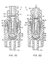
- Figures 3A-3D schematically show the cross-sectional view of the valve 5 shown in figure 2 as it is urged from a closed mode to an open mode. More particularly, figure 3A shows the valve 5 as a nozzle is about to be inserted through the proximal port 10. Figures 3B-3D show the nozzle at various stages of progression through the proximal port 10 and into the inlet housing 34. More particularly, as shown in figure 3A, the compressible member 41 occupies substantially all of the chamber volume when the valve 5 is in the closed mode. As the nozzle is inserted, however, the compressible member 41 compresses between the (distally moving) distal end of the cannula 14 (that acts as a plunger) and the distal end of the interior wall of the chamber 65.
- proximal chamber 66 a proximal region of the chamber 65
- distal chamber 67 a proximal region of the chamber 65
- the proximal chamber 66 has a volume that is about equal to or less than that of the distal chamber 67.
- the total available volume for containing liquid in the chamber 65 preferably is greater when the valve 5 is open than when the valve 5 is closed. Accordingly, when in the open mode (figure 3D), liquid can collect in the proximal chamber 66. As the nozzle is withdrawn, the volume of the proximal chamber 66 reduces and the volume of the compressible member 41 increases. This forces liquid from the proximal chamber 66 into the narrow channels 43, and then out the distal port 50. When the valve 5 returns to the closed mode, the proximal chamber 66 has a minimum volume while the compressible member 41 has a maximum volume.
- liquid may be directed to the distal port 50 by some other means. Accordingly, principles of the invention should not be limited to those embodiments requiring narrow channels 43.
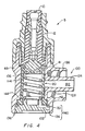
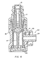
- Figure 4 shows a cross-sectional view of a second embodiment of the valve 5 shown in figure 1.
- the outlet housing portion 48 is reconfigured to have an orthogonal outlet 100 for directing fluid from the valve 5, and an end cap 102 at its distal end.
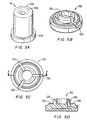
- the compressible member 41 is in the form of a hollow cylinder having a closed top portion, and an open bottom portion (figure 5A).
- the top portion comprises a top surface 104 having a depression 106 for receiving the bottom portion of the cannula 14.
- the bottom portion includes an annular flange 108 for securing the compressible member 41 within the valve 5 (discussed below).
- the compressible member 41 may be manufactured from any material used in the art, such as silicone, latex, or plastic, that can compress and decompress without significantly affecting its overall structure.
- the compressible member 41 is free standing within the chamber 65. Accordingly, when in the closed mode, the side of the compressible member 41 do not directly contact the side walls of the fluid chamber 65.
- the side of the compressible member 41 is between about 0.0508 mm to 0.254 mm (0.0022-0.010 inches) from the side walls of the chamber 65. This distance from the interior walls of the chamber 65 provides some additional clearance for compressing the compressible member 41. In other embodiments, there is no such clearance and thus, the compressible member 41 compresses by collapsing upon its interior only.
- the compressible member 41 in this embodiment includes a member interior 112 having a conventional spring 114 disposed therein.
- the spring 114 may be provided to supply additional proximal biasing force for normally biasing the member 41 in a proximal direction.
- the spring 114 may be any spring known in the art, such as a coil spring, or an integral piece of material that provides the additional biasing force (figure 6).
- the member interior 112 is empty and thus, it has no internal spring 114.
- the compressible member 41 preferably is manufactured from a material and/or with a geometry that normally biases the compressible member 41 proximally. In fact, such embodiments of the compressible member 41 themselves are springs. Additional details of such member geometry are discussed below with reference to figure 7.
- the valve 5 shown in figures 4 and 6 also differ from that shown in figures 1 in that it includes the outlet that extends from the side of the valve 5.
- the chamber 65 includes an interior wall that defines an opening 120 to an outlet channel 122 that is formed through an outlet tube 124.
- the outlet tube 124 may include an annular skirt 126 having threads 128 for coupling with a complimentary connector device.
- the outlet tube 124 thus is substantially orthogonal to the longitudinal dimension of the valve 5.
- the compressible member 41 may be positioned in the chamber 65 to normally occlude the outlet, thus preventing fluid flow from the chamber 65.
- the second illustrative embodiment of the valve 5 also includes the end cap 102, which is ultrasonically welded to its proximal end.
- the end cap 102 includes a top surface that forms a part of the member interior 112. The top surface thus defines three venting grooves 130, an annular protrusion 132 for securing the spring 114 (if any) within the member interior 112, and an annular ridge 134 for mating with a complimentary part of the valve housing for securing the end cap 102 to the valve 5.
- the cap 102 preferably is connected to the distal end of the housing so that it defines a small annular space 136 ("cap space 136," or referred to by those skilled in the art as a “reveal") between it and the housing.
- the cap space 136 is between about 0.0508 and 0.102 mm (0.002 and 0.004 inches).
- the bottom portion of the compressible member 41 is secured over the three venting grooves 130 to the top surface of the cap 102. Each groove is in fluid communication with the cap space 136 to form a vent 140 that vents the member interior 112 to the exterior of the valve 5.
- vents may be interpreted herein to include any channel that extends from the member interior 112 to the exterior of the valve 5. Accordingly, various embodiments of the invention are not to be limited to the specific disclosed vent configurations.
- the member interior 112 preferably is fluidly isolated from the rest of the chamber 65 ( i.e., the chamber area that is exterior to the compressible member 41).
- the outlet housing portion 48 includes a distal rim 144 that, when coupled with the end cap 102, compresses the annular flange 108 around the bottom portion of the compressible member 41 to form a liquid tight pinch-fit seal.
- This seal ensures that liquid does not leak into the member interior 112.
- the rim 144 may be flat, or, may converge to a pointed annular ring that pinches the member annular flange 108.
- the compressible member 41 When the compressible member 41 is compressed, air within the member chamber (i . e ., the chamber formed by the interior of the member 41) is forced out of the member interior 112 through the vents, thus facilitating compression of the compressible member 41.
- the resistence to compressing the compressible member 41 may be adjusted by adjusting the size and geometry of the vents. Conversely, when the compressible member 41 is decompressed, air from the exterior of the valve 5 is drawn into the member interior 112, thus facilitating decompression of the compressible member 41.
- the compressible member 41 when in the closed mode, the compressible member 41 is fully decompressed, thus causing the proximal chamber 66 to have a minimum volume.
- the compressible member 41 When in the open mode, the compressible member 41 is compressed to enlarge the proximal chamber 66 to its maximum volume. Liquid or other fluid injected through the cannula 14 and transverse gland 12 28 thus flows into the proximal chamber 66, and out of the valve 5 through the outlet.
- this embodiment of the valve 5 may have one or more narrow flow channels (similar to those in the valve 5 of figure 1), or the clearance between the compressible member 41 and the interior wall of the chamber 65 may form a channel.
- the compressible member 41 normally occludes the outlet. Accordingly, to open the valve 5, the compressible member 41 of this version must be forced distally until the top of the compressible member 41 is more distal than the top of the outlet channel 122, thus fluidly communicating the proximal chamber 66 with the outlet.
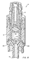
- Figure 7 shows a cross-section of a third illustrative embodiment of the valve 5 shown in figure 1.
- this embodiment includes the orthogonal outlet 100, the compressible member 41 with an open distal end, and the vented end cap 102.
- the top portion of the compressible member 41 is contoured to a complimentary shape to that of the bottom portion of the cannula 14.
- both the bottom portion of the cannula 14 and the top portion of the cannula 14 are flat.
- Each of the embodiments described herein may have a similar complimentary geometry.
- the compressible member 41 also is shaped in a distally bowed configuration to further enhance its proximal biasing force.
- the compressible member 41 of this embodiment includes an upper portion 148 having a substantially uniform outer diameter, a diverging middle portion 150 having a distally expanding outer diameter, and a lower portion 152 having a substantially uniform inner diameter.
- the lower portion 152 includes the annular flange 108 for securing the compressible member 41 within the complimentary recess of the valve 5.
- the upper portion 148 includes an inner surface 154 ( i.e., defining a portion of the member interior 112) having a substantially uniform radius for providing support for the cannula 14 upon its top portion.
- this embodiment of the valve 5 does not include a spring with the member interior 112. Although not necessary, one may be provided to further proximally bias the compressible member 41.
- Some versions of this embodiment may utilize an inverted cone type of compressible member 41 (not shown), where the compressible member 41 has an hourglass shape. Similar to the distally bowed compressible member 41, a compressible member 41 in an inverted cone configuration generally readily returns to its normal uncompressed state when distally applied force is not applied to its top portion.
- Figure 8 schematically shows a fourth illustrative embodiment of the valve 5 shown in figure 1.
- the distal port is located at the proximal end of the valve 5 and not orthogonal to the flow channel through the cannula 14.
- the compressible member 41 is hollow and open distal ended similar to the embodiment shown in figure 5A. It should be noted that although the compressible member 41 with a substantially uniform outer diameter is shown, various other compressible members may be utilized, such as the compressible member 41 shown in figure 7. Although not shown, some versions of this embodiment include a spring 114 within the member interior 112.
- the chamber 65 in the fourth illustrative embodiment forms a vent 155 that extends through the housing, thus venting the member interior 112 to the atmosphere.
- this embodiment also includes two distal flow channels 156 that fluidly connect the chamber 65 ( i.e., the part of the chamber 65 that is external to the member interior 112) with the distal port 50. Accordingly, when in the open mode, fluid is directed from the proximal chamber 66, through the narrow flow channel(s) 43 in the side of the interior walls to the distal flow channels 156, to the distal port 50. Moreover, when the compressible member 41 is compressed, air is expelled from the member interior 112 via the vent 155. In a similar manner, when the compressible member 41 decompresses, air is drawn into the member interior 112 to facilitate its decompression.
- a swab valve is shown in the disclosed embodiments, other valves may be utilized in accord with the various embodiments disclosed herein.
- the slit top surface of the gland 12 may be substantially flush with the proximal opening to the valve 5 ( e.g. , see figure 8), while in other embodiments, such surface extends above the proximal opening ( e.g. , see figure 4).
Landscapes
- Health & Medical Sciences (AREA)
- Heart & Thoracic Surgery (AREA)
- Animal Behavior & Ethology (AREA)
- General Health & Medical Sciences (AREA)
- Anesthesiology (AREA)
- Biomedical Technology (AREA)
- Hematology (AREA)
- Life Sciences & Earth Sciences (AREA)
- Pulmonology (AREA)
- Engineering & Computer Science (AREA)
- Public Health (AREA)
- Veterinary Medicine (AREA)
- Infusion, Injection, And Reservoir Apparatuses (AREA)
- Media Introduction/Drainage Providing Device (AREA)
- External Artificial Organs (AREA)
- Endoscopes (AREA)
Applications Claiming Priority (3)
| Application Number | Priority Date | Filing Date | Title |
|---|---|---|---|
| US11735999P | 1999-01-27 | 1999-01-27 | |
| US117359P | 1999-01-27 | ||
| PCT/US2000/000336 WO2000044433A2 (en) | 1999-01-27 | 2000-01-07 | Apparatus for reducing fluid drawback through a medical valve |
Publications (2)
| Publication Number | Publication Date |
|---|---|
| EP1171187A2 EP1171187A2 (en) | 2002-01-16 |
| EP1171187B1 true EP1171187B1 (en) | 2005-06-15 |
Family
ID=22372470
Family Applications (1)
| Application Number | Title | Priority Date | Filing Date |
|---|---|---|---|
| EP00903148A Expired - Lifetime EP1171187B1 (en) | 1999-01-27 | 2000-01-07 | Apparatus for reducing fluid drawback through a medical valve |
Country Status (8)
| Country | Link |
|---|---|
| EP (1) | EP1171187B1 (enExample) |
| JP (1) | JP2002535098A (enExample) |
| KR (1) | KR100629810B1 (enExample) |
| AT (1) | ATE297784T1 (enExample) |
| AU (1) | AU769722B2 (enExample) |
| CA (1) | CA2357740A1 (enExample) |
| DE (1) | DE60020826T2 (enExample) |
| WO (1) | WO2000044433A2 (enExample) |
Families Citing this family (17)
| Publication number | Priority date | Publication date | Assignee | Title |
|---|---|---|---|---|
| US6883778B1 (en) | 1996-11-18 | 2005-04-26 | Nypro Inc. | Apparatus for reducing fluid drawback through a medical valve |
| US6228069B1 (en) * | 1999-04-05 | 2001-05-08 | Filtertek Inc. | Needleless access device |
| US6755391B2 (en) | 2000-10-23 | 2004-06-29 | Nypro Inc. | Anti-drawback medical valve |
| KR20040036918A (ko) | 2001-08-22 | 2004-05-03 | 나이프로, 인크. | 팽창가능한 부재를 구비한 의료용 밸브 |
| US7837658B2 (en) | 2001-11-13 | 2010-11-23 | Nypro Inc. | Anti-drawback medical valve |
| US6869426B2 (en) | 2001-11-13 | 2005-03-22 | Nypro Inc. | Anti-drawback medical valve |
| DE10231060B4 (de) | 2002-07-10 | 2018-05-24 | Mann + Hummel Gmbh | Filterelement, Verfahren zu dessen Herstellung und Verwendung des Filterelements |
| US7357792B2 (en) | 2002-10-29 | 2008-04-15 | Nypro Inc. | Positive push medical valve with internal seal |
| US7914502B2 (en) | 2003-07-31 | 2011-03-29 | Nypro Inc. | Anti-drawback medical valve |
| US7857284B2 (en) | 2006-04-11 | 2010-12-28 | Nypro Inc. | Medical valve with movable member |
| AU2010264501B2 (en) | 2009-06-22 | 2015-03-12 | Np Medical Inc. | Medical valve with improved back-pressure sealing |
| US9138572B2 (en) | 2010-06-24 | 2015-09-22 | Np Medical Inc. | Medical valve with fluid volume alteration |
| CN103796695B (zh) * | 2011-05-01 | 2016-04-20 | 霍基-罗伯茨公司 | 凸出式回流阀 |
| RU2518704C2 (ru) * | 2012-09-10 | 2014-06-10 | Общество с ограниченной ответственностью Научно-производственная фирма "МКТ-АСДМ" | Узел затвора клиновой задвижки |
| WO2018169670A1 (en) * | 2017-03-13 | 2018-09-20 | Boston Scientific Limited | Hemostasis valves and methods for making and using hemostasis valves |
| CN109876225B (zh) * | 2019-03-25 | 2021-02-26 | 刘婷 | 一种临床护理用易调控伤口冲洗装置 |
| FR3117569B1 (fr) * | 2020-12-16 | 2022-11-25 | Parker Hannifin Emea Sarl | Dispositif de raccordement aseptique d’un tube |
Citations (1)
| Publication number | Priority date | Publication date | Assignee | Title |
|---|---|---|---|---|
| WO1998022178A1 (en) * | 1996-11-18 | 1998-05-28 | Nypro, Inc. | Swabbable luer-coned valve |
Family Cites Families (11)
| Publication number | Priority date | Publication date | Assignee | Title |
|---|---|---|---|---|
| US3192949A (en) * | 1962-07-10 | 1965-07-06 | Halkey Roberts Corp | Spring biased check valve |
| US3831629A (en) * | 1972-01-24 | 1974-08-27 | Halkey Roberts Corp | Check valve |
| US4116201A (en) * | 1976-12-20 | 1978-09-26 | The Kendall Company | Catheter with inflation control device |
| GB2079162B (en) * | 1980-07-04 | 1983-11-16 | Commw Ind Gases | Resuscitator valve assembly |
| EP0099360A1 (en) * | 1982-01-28 | 1984-02-01 | Whitman Medical Corporation | Safety valve for preventing air embolism or hemorrhage |
| US4758224A (en) * | 1985-03-25 | 1988-07-19 | Siposs George G | Suction control valve for left ventricle venting |
| GB8627808D0 (en) * | 1986-11-20 | 1986-12-17 | Cox J A | Sampling liquids from human/animal body |
| US5401255A (en) * | 1993-07-20 | 1995-03-28 | Baxter International Inc. | Multi-functional valve with unitary valving member and improved safety |
| US5320328A (en) * | 1993-08-09 | 1994-06-14 | Sherwood Medical Company | Suction control valve with vacuum breaker |
| US5549566A (en) * | 1994-10-27 | 1996-08-27 | Abbott Laboratories | Valved intravenous fluid line infusion device |
| US5569209A (en) * | 1994-12-21 | 1996-10-29 | Jemm Tran-Safe Systems, Inc. | Needleless transfer system |
-
2000
- 2000-01-07 CA CA002357740A patent/CA2357740A1/en not_active Abandoned
- 2000-01-07 EP EP00903148A patent/EP1171187B1/en not_active Expired - Lifetime
- 2000-01-07 JP JP2000595733A patent/JP2002535098A/ja active Pending
- 2000-01-07 AU AU24936/00A patent/AU769722B2/en not_active Ceased
- 2000-01-07 WO PCT/US2000/000336 patent/WO2000044433A2/en not_active Ceased
- 2000-01-07 DE DE60020826T patent/DE60020826T2/de not_active Expired - Fee Related
- 2000-01-07 KR KR1020017009379A patent/KR100629810B1/ko not_active Expired - Fee Related
- 2000-01-07 AT AT00903148T patent/ATE297784T1/de not_active IP Right Cessation
Patent Citations (2)
| Publication number | Priority date | Publication date | Assignee | Title |
|---|---|---|---|---|
| WO1998022178A1 (en) * | 1996-11-18 | 1998-05-28 | Nypro, Inc. | Swabbable luer-coned valve |
| US6039302A (en) * | 1996-11-18 | 2000-03-21 | Nypro Inc. | Swabbable luer-activated valve |
Also Published As
| Publication number | Publication date |
|---|---|
| ATE297784T1 (de) | 2005-07-15 |
| WO2000044433A3 (en) | 2001-01-18 |
| EP1171187A2 (en) | 2002-01-16 |
| CA2357740A1 (en) | 2000-08-03 |
| DE60020826T2 (de) | 2006-05-04 |
| JP2002535098A (ja) | 2002-10-22 |
| KR20010101702A (ko) | 2001-11-14 |
| AU2493600A (en) | 2000-08-18 |
| KR100629810B1 (ko) | 2006-09-29 |
| AU769722B2 (en) | 2004-02-05 |
| WO2000044433A2 (en) | 2000-08-03 |
| DE60020826D1 (de) | 2005-07-21 |
Similar Documents
| Publication | Publication Date | Title |
|---|---|---|
| US6883778B1 (en) | Apparatus for reducing fluid drawback through a medical valve | |
| EP1171187B1 (en) | Apparatus for reducing fluid drawback through a medical valve | |
| US7014169B2 (en) | Anti-drawback medical valve | |
| US7753892B2 (en) | Anti-drawback medical valve | |
| RU2225232C2 (ru) | Медицинский клапан со свойствами создания положительного потока | |
| EP1656179B1 (en) | Anti-drawback medical valve | |
| US6068011A (en) | Control of fluid flow | |
| US8876784B2 (en) | Anti-drawback medical valve | |
| US7396348B2 (en) | Medical valve with expandable member | |
| NZ536325A (en) | Needle-free medical connector with expandable valve mechanism and method of fluid flow control | |
| NZ533216A (en) | Needle free medical connector with expanded valve mechanism and method of fluid flow control | |
| WO2007047060A2 (en) | Valve for intravenous catheter | |
| US20020029020A1 (en) | Apparatus for reducing fluid drawback through a medical valve | |
| HK1200745B (en) | Medical connectors and methods of use | |
| AU2002356132A1 (en) | Medical valve with expandable seal member |
Legal Events
| Date | Code | Title | Description |
|---|---|---|---|
| PUAI | Public reference made under article 153(3) epc to a published international application that has entered the european phase |
Free format text: ORIGINAL CODE: 0009012 |
|
| 17P | Request for examination filed |
Effective date: 20010712 |
|
| AK | Designated contracting states |
Kind code of ref document: A2 Designated state(s): AT BE CH CY DE DK ES FI FR GB GR IE IT LI LU MC NL PT SE |
|
| AX | Request for extension of the european patent |
Free format text: AL;LT;LV;MK;RO;SI |
|
| 17Q | First examination report despatched |
Effective date: 20030417 |
|
| GRAP | Despatch of communication of intention to grant a patent |
Free format text: ORIGINAL CODE: EPIDOSNIGR1 |
|
| GRAS | Grant fee paid |
Free format text: ORIGINAL CODE: EPIDOSNIGR3 |
|
| GRAA | (expected) grant |
Free format text: ORIGINAL CODE: 0009210 |
|
| AK | Designated contracting states |
Kind code of ref document: B1 Designated state(s): AT BE CH CY DE DK ES FI FR GB GR IE IT LI LU MC NL PT SE |
|
| PG25 | Lapsed in a contracting state [announced via postgrant information from national office to epo] |
Ref country code: IT Free format text: LAPSE BECAUSE OF FAILURE TO SUBMIT A TRANSLATION OF THE DESCRIPTION OR TO PAY THE FEE WITHIN THE PRE;WARNING: LAPSES OF ITALIAN PATENTS WITH EFFECTIVE DATE BEFORE 2007 MAY HAVE OCCURRED AT ANY TIME BEFORE 2007. THE CORRECT EFFECTIVE DATE MAY BE DIFFERENT FROM THE ONE RECORDED.SCRIBED TIME-LIMIT Effective date: 20050615 Ref country code: FI Free format text: LAPSE BECAUSE OF FAILURE TO SUBMIT A TRANSLATION OF THE DESCRIPTION OR TO PAY THE FEE WITHIN THE PRESCRIBED TIME-LIMIT Effective date: 20050615 Ref country code: BE Free format text: LAPSE BECAUSE OF FAILURE TO SUBMIT A TRANSLATION OF THE DESCRIPTION OR TO PAY THE FEE WITHIN THE PRESCRIBED TIME-LIMIT Effective date: 20050615 Ref country code: CH Free format text: LAPSE BECAUSE OF FAILURE TO SUBMIT A TRANSLATION OF THE DESCRIPTION OR TO PAY THE FEE WITHIN THE PRESCRIBED TIME-LIMIT Effective date: 20050615 Ref country code: AT Free format text: LAPSE BECAUSE OF FAILURE TO SUBMIT A TRANSLATION OF THE DESCRIPTION OR TO PAY THE FEE WITHIN THE PRESCRIBED TIME-LIMIT Effective date: 20050615 Ref country code: LI Free format text: LAPSE BECAUSE OF FAILURE TO SUBMIT A TRANSLATION OF THE DESCRIPTION OR TO PAY THE FEE WITHIN THE PRESCRIBED TIME-LIMIT Effective date: 20050615 Ref country code: NL Free format text: LAPSE BECAUSE OF FAILURE TO SUBMIT A TRANSLATION OF THE DESCRIPTION OR TO PAY THE FEE WITHIN THE PRESCRIBED TIME-LIMIT Effective date: 20050615 |
|
| REG | Reference to a national code |
Ref country code: GB Ref legal event code: FG4D Ref country code: CH Ref legal event code: EP |
|
| REF | Corresponds to: |
Ref document number: 60020826 Country of ref document: DE Date of ref document: 20050721 Kind code of ref document: P |
|
| REG | Reference to a national code |
Ref country code: IE Ref legal event code: FG4D |
|
| PG25 | Lapsed in a contracting state [announced via postgrant information from national office to epo] |
Ref country code: SE Free format text: LAPSE BECAUSE OF FAILURE TO SUBMIT A TRANSLATION OF THE DESCRIPTION OR TO PAY THE FEE WITHIN THE PRESCRIBED TIME-LIMIT Effective date: 20050915 Ref country code: GR Free format text: LAPSE BECAUSE OF FAILURE TO SUBMIT A TRANSLATION OF THE DESCRIPTION OR TO PAY THE FEE WITHIN THE PRESCRIBED TIME-LIMIT Effective date: 20050915 Ref country code: DK Free format text: LAPSE BECAUSE OF FAILURE TO SUBMIT A TRANSLATION OF THE DESCRIPTION OR TO PAY THE FEE WITHIN THE PRESCRIBED TIME-LIMIT Effective date: 20050915 |
|
| PG25 | Lapsed in a contracting state [announced via postgrant information from national office to epo] |
Ref country code: ES Free format text: LAPSE BECAUSE OF FAILURE TO SUBMIT A TRANSLATION OF THE DESCRIPTION OR TO PAY THE FEE WITHIN THE PRESCRIBED TIME-LIMIT Effective date: 20050926 |
|
| PG25 | Lapsed in a contracting state [announced via postgrant information from national office to epo] |
Ref country code: PT Free format text: LAPSE BECAUSE OF FAILURE TO SUBMIT A TRANSLATION OF THE DESCRIPTION OR TO PAY THE FEE WITHIN THE PRESCRIBED TIME-LIMIT Effective date: 20051124 |
|
| NLV1 | Nl: lapsed or annulled due to failure to fulfill the requirements of art. 29p and 29m of the patents act | ||
| REG | Reference to a national code |
Ref country code: CH Ref legal event code: PL |
|
| PG25 | Lapsed in a contracting state [announced via postgrant information from national office to epo] |
Ref country code: IE Free format text: LAPSE BECAUSE OF NON-PAYMENT OF DUE FEES Effective date: 20060109 |
|
| PG25 | Lapsed in a contracting state [announced via postgrant information from national office to epo] |
Ref country code: LU Free format text: LAPSE BECAUSE OF NON-PAYMENT OF DUE FEES Effective date: 20060131 Ref country code: MC Free format text: LAPSE BECAUSE OF NON-PAYMENT OF DUE FEES Effective date: 20060131 |
|
| ET | Fr: translation filed | ||
| PLBE | No opposition filed within time limit |
Free format text: ORIGINAL CODE: 0009261 |
|
| STAA | Information on the status of an ep patent application or granted ep patent |
Free format text: STATUS: NO OPPOSITION FILED WITHIN TIME LIMIT |
|
| 26N | No opposition filed |
Effective date: 20060316 |
|
| REG | Reference to a national code |
Ref country code: IE Ref legal event code: MM4A |
|
| PGFP | Annual fee paid to national office [announced via postgrant information from national office to epo] |
Ref country code: GB Payment date: 20080129 Year of fee payment: 9 |
|
| PGFP | Annual fee paid to national office [announced via postgrant information from national office to epo] |
Ref country code: DE Payment date: 20080229 Year of fee payment: 9 Ref country code: FR Payment date: 20080117 Year of fee payment: 9 |
|
| PG25 | Lapsed in a contracting state [announced via postgrant information from national office to epo] |
Ref country code: CY Free format text: LAPSE BECAUSE OF FAILURE TO SUBMIT A TRANSLATION OF THE DESCRIPTION OR TO PAY THE FEE WITHIN THE PRESCRIBED TIME-LIMIT Effective date: 20050615 |
|
| GBPC | Gb: european patent ceased through non-payment of renewal fee |
Effective date: 20090107 |
|
| PG25 | Lapsed in a contracting state [announced via postgrant information from national office to epo] |
Ref country code: DE Free format text: LAPSE BECAUSE OF NON-PAYMENT OF DUE FEES Effective date: 20090801 |
|
| REG | Reference to a national code |
Ref country code: FR Ref legal event code: ST Effective date: 20091030 |
|
| PG25 | Lapsed in a contracting state [announced via postgrant information from national office to epo] |
Ref country code: GB Free format text: LAPSE BECAUSE OF NON-PAYMENT OF DUE FEES Effective date: 20090107 |
|
| PG25 | Lapsed in a contracting state [announced via postgrant information from national office to epo] |
Ref country code: FR Free format text: LAPSE BECAUSE OF NON-PAYMENT OF DUE FEES Effective date: 20090202 |