EP1170942A1 - Image synthesizing device, recorded medium, and program - Google Patents
Image synthesizing device, recorded medium, and program Download PDFInfo
- Publication number
- EP1170942A1 EP1170942A1 EP01901545A EP01901545A EP1170942A1 EP 1170942 A1 EP1170942 A1 EP 1170942A1 EP 01901545 A EP01901545 A EP 01901545A EP 01901545 A EP01901545 A EP 01901545A EP 1170942 A1 EP1170942 A1 EP 1170942A1
- Authority
- EP
- European Patent Office
- Prior art keywords
- image
- compositing
- images
- graphical
- video
- Prior art date
- Legal status (The legal status is an assumption and is not a legal conclusion. Google has not performed a legal analysis and makes no representation as to the accuracy of the status listed.)
- Withdrawn
Links
Images












Classifications
-
- H—ELECTRICITY
- H04—ELECTRIC COMMUNICATION TECHNIQUE
- H04N—PICTORIAL COMMUNICATION, e.g. TELEVISION
- H04N21/00—Selective content distribution, e.g. interactive television or video on demand [VOD]
- H04N21/40—Client devices specifically adapted for the reception of or interaction with content, e.g. set-top-box [STB]; Operations thereof
- H04N21/47—End-user applications
-
- G—PHYSICS
- G09—EDUCATION; CRYPTOGRAPHY; DISPLAY; ADVERTISING; SEALS
- G09G—ARRANGEMENTS OR CIRCUITS FOR CONTROL OF INDICATING DEVICES USING STATIC MEANS TO PRESENT VARIABLE INFORMATION
- G09G5/00—Control arrangements or circuits for visual indicators common to cathode-ray tube indicators and other visual indicators
- G09G5/14—Display of multiple viewports
-
- G—PHYSICS
- G09—EDUCATION; CRYPTOGRAPHY; DISPLAY; ADVERTISING; SEALS
- G09G—ARRANGEMENTS OR CIRCUITS FOR CONTROL OF INDICATING DEVICES USING STATIC MEANS TO PRESENT VARIABLE INFORMATION
- G09G5/00—Control arrangements or circuits for visual indicators common to cathode-ray tube indicators and other visual indicators
- G09G5/36—Control arrangements or circuits for visual indicators common to cathode-ray tube indicators and other visual indicators characterised by the display of a graphic pattern, e.g. using an all-points-addressable [APA] memory
- G09G5/39—Control of the bit-mapped memory
- G09G5/395—Arrangements specially adapted for transferring the contents of the bit-mapped memory to the screen
- G09G5/397—Arrangements specially adapted for transferring the contents of two or more bit-mapped memories to the screen simultaneously, e.g. for mixing or overlay
-
- H—ELECTRICITY
- H04—ELECTRIC COMMUNICATION TECHNIQUE
- H04N—PICTORIAL COMMUNICATION, e.g. TELEVISION
- H04N21/00—Selective content distribution, e.g. interactive television or video on demand [VOD]
- H04N21/40—Client devices specifically adapted for the reception of or interaction with content, e.g. set-top-box [STB]; Operations thereof
- H04N21/43—Processing of content or additional data, e.g. demultiplexing additional data from a digital video stream; Elementary client operations, e.g. monitoring of home network or synchronising decoder's clock; Client middleware
- H04N21/431—Generation of visual interfaces for content selection or interaction; Content or additional data rendering
-
- H—ELECTRICITY
- H04—ELECTRIC COMMUNICATION TECHNIQUE
- H04N—PICTORIAL COMMUNICATION, e.g. TELEVISION
- H04N21/00—Selective content distribution, e.g. interactive television or video on demand [VOD]
- H04N21/40—Client devices specifically adapted for the reception of or interaction with content, e.g. set-top-box [STB]; Operations thereof
- H04N21/43—Processing of content or additional data, e.g. demultiplexing additional data from a digital video stream; Elementary client operations, e.g. monitoring of home network or synchronising decoder's clock; Client middleware
- H04N21/44—Processing of video elementary streams, e.g. splicing a video clip retrieved from local storage with an incoming video stream or rendering scenes according to encoded video stream scene graphs
- H04N21/44004—Processing of video elementary streams, e.g. splicing a video clip retrieved from local storage with an incoming video stream or rendering scenes according to encoded video stream scene graphs involving video buffer management, e.g. video decoder buffer or video display buffer
-
- H—ELECTRICITY
- H04—ELECTRIC COMMUNICATION TECHNIQUE
- H04N—PICTORIAL COMMUNICATION, e.g. TELEVISION
- H04N21/00—Selective content distribution, e.g. interactive television or video on demand [VOD]
- H04N21/40—Client devices specifically adapted for the reception of or interaction with content, e.g. set-top-box [STB]; Operations thereof
- H04N21/47—End-user applications
- H04N21/482—End-user interface for programme selection
-
- H—ELECTRICITY
- H04—ELECTRIC COMMUNICATION TECHNIQUE
- H04N—PICTORIAL COMMUNICATION, e.g. TELEVISION
- H04N5/00—Details of television systems
- H04N5/222—Studio circuitry; Studio devices; Studio equipment
- H04N5/262—Studio circuits, e.g. for mixing, switching-over, change of character of image, other special effects ; Cameras specially adapted for the electronic generation of special effects
- H04N5/265—Mixing
-
- G—PHYSICS
- G09—EDUCATION; CRYPTOGRAPHY; DISPLAY; ADVERTISING; SEALS
- G09G—ARRANGEMENTS OR CIRCUITS FOR CONTROL OF INDICATING DEVICES USING STATIC MEANS TO PRESENT VARIABLE INFORMATION
- G09G2340/00—Aspects of display data processing
- G09G2340/10—Mixing of images, i.e. displayed pixel being the result of an operation, e.g. adding, on the corresponding input pixels
-
- G—PHYSICS
- G09—EDUCATION; CRYPTOGRAPHY; DISPLAY; ADVERTISING; SEALS
- G09G—ARRANGEMENTS OR CIRCUITS FOR CONTROL OF INDICATING DEVICES USING STATIC MEANS TO PRESENT VARIABLE INFORMATION
- G09G2340/00—Aspects of display data processing
- G09G2340/12—Overlay of images, i.e. displayed pixel being the result of switching between the corresponding input pixels
- G09G2340/125—Overlay of images, i.e. displayed pixel being the result of switching between the corresponding input pixels wherein one of the images is motion video
-
- H—ELECTRICITY
- H04—ELECTRIC COMMUNICATION TECHNIQUE
- H04N—PICTORIAL COMMUNICATION, e.g. TELEVISION
- H04N9/00—Details of colour television systems
- H04N9/64—Circuits for processing colour signals
Definitions
- Images can be composited at high speed by providing the planes that correspond to the images and a plurality of pieces of hardware that perform the ⁇ blending algorithm and that also correspond to the images. In this case, however, hardware cost is raised. Also, many planes are needed. This is problematic.
- image compositing apparatus still and video images can be composited together for which the ⁇ values and the compositing order have been defined.
- the layout of images for which the ⁇ values have been defined can be more flexibly changed compared with images for which the composition ratios to the final composite image have been defined. This is an advantage. Accordingly, the image compositing apparatus that composites images using ⁇ values can deal with a variety of EPG display layouts.
- the size indicates the height "H” and the width "W” of the rectangular component.
- the height "H” and width “W” are each represented in pixel units.
- the video plane 106 is composed of memory or the like.
- the video plane 106 holds video image data that has been stored by the video reproducing unit 105 and a composite ⁇ value that has been stored by the second compositing unit 109.
- a composite ⁇ value indicates the transparency of one of a plurality of pixels when the plurality of pixels are combined. More specifically, the composite ⁇ values held by the video plane 106 indicate the transparency of the pixels of the video image component when the plurality of components are composited.
- the first compositing unit 108 initializes the OSD plane 107 (step S800). More specifically, all the areas for RGB components are set to be "0" on the OSD plane 107.
- step S807 When the first compositing unit 108 has performed the processing for all the image files as has been described, the first compositing processing is completed (step S807).
- the EPG display instructions is sent to the other elements via the controller 102.
- the EPG generating unit 103 When receiving the EPG instructions, the EPG generating unit 103 generates image files and an index file according to the EPG information that has been broadcast. The generated image files and index file are stored in the image holding unit 104. Also, the EPG generating unit 103 informs the video reproducing unit 105 of the position and size of the video image component that has been obtained when generating the image files (step S1002).
- Fig. 15 is a block diagram showing the structure of an image compositing apparatus according to the second embodiment of the present invention.
- Fig. 17 is a chart for explaining the flow of the operations by the image compositing apparatus 200 at the time of EPG display.
- operations by elements of the image compositing apparatus 200 are indicated in the rectangles and the data flow by the arrows. Note that at the steps in the flowchart in Fig. 17 that have the same reference numbers as in the flowchart in Fig. 11, the same operations as in Fig. 11 are performed.
- each of the ⁇ value of the lower component "i" after the switch is indicated by the term ⁇ i+1' and each of the ⁇ values of the upper component "i+1" the term ⁇ i'.
- ⁇ i+1' ⁇ i+1 1- ⁇ i(1- ⁇ i+1)
- ⁇ i' ⁇ i (1- ⁇ i+1)
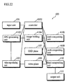
- an image compositing apparatus 300 includes the input unit 101, a controller 2000, an EPG generating unit 2003, the image holding unit 104, a video reproducing unit 2001, a video plane 2002, the OSD plane 107, a sixth compositing unit 2004, a seventh compositing unit 2005, an eighth compositing unit 2006, and the output unit 111.
- the image compositing apparatus 300 composites a plurality of video image components with a plurality of graphical image components. Note that the elements that have the same reference numbers as of the image compositing apparatuses 100 and 200 have the same functions. The following explanation will focus on the elements that have the different reference numbers from the image compositing apparatuses 100 and 200.
- the controller 2000 controls all the elements of the image compositing apparatus 300. More specifically, when the user instructs to turn the image compositing apparatus 300 ON, the controller 2000 has the video reproducing unit 2001 reproduce a program. When the user instructs to switch channels, the controller 2000 has the video reproducing unit 2001 reproduce another program. When the user instructs to turn the EPG display ON, the controller 2000 controls the EPG generating unit 2003, the video reproducing unit 2001, the sixth compositing unit 2004, the seventh compositing unit 2005, the eighth compositing unit 2006, and the like so as to generate a composite image.
- the seventh compositing unit 2005 reads from the image holding unit 104 the image file "i" that has been stored in the storage position indicated by the image information "i" (step S2102).
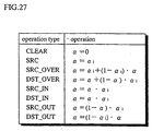
- the tenth compositing unit 4109 When receiving instructions from the controller 4102, the tenth compositing unit 4109 generates the ⁇ values of the video plane 106 to the OSD plane 107 from the image data stored in the image holding unit 4104. The generated ⁇ values are stored on the video plane 106.
- the tenth compositing unit 4109 performs an operation shown in Fig. 30 in pixel units according to the operation type.
- the ninth compositing unit 4108 operates in synchronization with the tenth compositing unit 4109.
- the results at steps S4802, S803, S804, and S807 may be used.
- the operations at steps S1202, S903, S904, and S907 may be performed in synchronization with the operations at steps S4802, S803, S804, and S807. Meanwhile, the operations at steps S4905 and 4906 need to be completed before the operation at step S807.
Landscapes
- Engineering & Computer Science (AREA)
- Multimedia (AREA)
- Signal Processing (AREA)
- Physics & Mathematics (AREA)
- Computer Hardware Design (AREA)
- General Physics & Mathematics (AREA)
- Theoretical Computer Science (AREA)
- Human Computer Interaction (AREA)
- Studio Circuits (AREA)
- Image Processing (AREA)
- Controls And Circuits For Display Device (AREA)
Abstract
An image compositing apparatus of the present invention
composites a video image and a plurality of graphical images'
together into a final composite image. The image compositing
apparatus includes a first obtaining unit, a first compositing
unit, a calculating unit, a second obtaining unit, and a second
compositing unit. The first obtaining unit obtains the
graphical images and composition information that includes an
image compositing order and is used for calculating the
composition ratios of the images to the final composite image.
The first compositing unit composites the graphical images
together into one composite graphical image according to the
composition information. The calculating unit calculates the
composition ratio of the video image to the final composite
image according to the composition information. The second
obtaining unit obtains frames of the video image. The second
compositing unit composites the frames with the composite
graphical image using the composition ratio of the video image.
Description
The present invention relates to an image compositing
apparatus for compositing a plurality of images to output a
final image.
Recently digital broadcasting has started. In the
digital TV set used for the digital broadcasting, graphical
images are generated according to data from a broadcasting
station and the generated graphical images are overlaid on
video images of a program when displayed.
For this purpose, the digital TV set is equipped with
an image compositing apparatus.
The image compositing apparatus performs a predetermined
operation between pixels for images F and G to output an image
H. In the inter-pixel operation, a pixel f(x,y) of the image
F and a pixel g(x,y), which corresponds to the pixel f(x,y),
of the image G are used to generate a pixel h(x,y) of the image
H.
One method of the inter-pixel operation is the α blending
algorithm. In the α blending algorithm, the weighted average
of the pixels f(x,y) and g(x,y) is the pixel h(x,y). Suppose
that the weighting factor for the pixel g(x,y) is "α", the α
blending algorithm is given below.
h(x,y) = α*g(x,y)+(1-α)*f(x,y)
where, "*"indicates multiplication
In this equation, the weighting factor is referred to
as an "α value", a "transparency", a "blending factor" or the
like. The value of the weighting factor is "0" to "1".
When the α value is "0", the pixel g(x,y) is completely
transparent and the pixel f(x,y) as it is becomes the combined
pixel h(x,y). On the other hand, when the α value is "1", the
pixel g(x,y) is completely opaque and the pixel g(x,y) as it
is becomes the pixel h(x,y). When the α value is "0.5", the
pixel h(x,y) is a composite of 50% of the pixel g(x,y) and 50%
of the pixel f(x,y). In this manner, the α value indicates
how an image is overlaid on another image. In the actual
hardware, each pixel is represented by RGB (Red, Green, and
Blue) color components, so that the arithmetic operation
indicated above is performed for each of the components.
For compositing graphical images and video images
together in real time, the image compositing apparatus
includes an OSD (On Screen Display) plane, which is a memory
area for developing graphical images, and a video plane, which
is another memory area for developing video images in frame
units. Whenever a frame on the video plane is updated, images
in the two areas are composited together according to the α
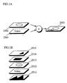
blending algorithm to output a composite image. Fig. 1A is
a conceptual diagram showing how images on an OSD plane 2501
and a video plane 2502 are composited together to output a
composite image 2503.
Meanwhile, the recent digital broadcasting requires to
overlay a plurality of graphical images 2511, 2513, 2514, and
2515, which indicate the title and TV programs and the like,
on a video image 2512 of a program while the video image 2512
is reproduced as shown in Fig. 1B.
Theoretically, it is enough to perform the α blending'
algorithm for images to be composited together in turn from
the bottom to the top in order to composite a video image and
a plurality of graphical images together. Actually, however,
a large amount of arithmetic operations is performed for the
α blending algorithm for a plurality of images, so that it is
extremely difficult to composite a plurality of images in real
time whenever a frame of video images is updated.
Images can be composited at high speed by providing the
planes that correspond to the images and a plurality of pieces
of hardware that perform the α blending algorithm and that also
correspond to the images. In this case, however, hardware cost
is raised. Also, many planes are needed. This is
problematic.
It is accordingly an object of the present invention to
provide an image compositing apparatus that composites images
together in real time according to the reproduction rate of
video images, i.e., at high speed.
Another object of the present invention is to provide
an image compositing apparatus with fewer memories for image
development.
The above-mentioned first and second objects may be
achieved by an image compositing apparatus that composites
images together into a final composite image, the images
including a video image and a plurality of graphical images,
the image compositing apparatus including: a first obtaining
unit that obtains the graphical images and composition
information including an image compositing order, the
composition information being used for calculating a'
composition ratio of each of the images to the final composite
image; a first compositing unit that composites the graphical
images to generate one composite graphical image according to
the composition information; a calculating unit that
calculates a composition ratio of the video image to the final
composite image according to the composition information; a
second obtaining unit that obtains frames of the video image;
and a second compositing unit that composites one of the
obtained frames at a time with the composite graphical image
using the composition ratio of the video image.
In this image compositing apparatus, the graphical
images are composited together and the composition ratio of
the video image is calculated before the frames of the video
image are composited with the composite graphical image.
Accordingly, it is not necessary to composite a plurality of
graphical images with a video image for each of the frames
unlike the conventional manner. As a result, the calculation
is performed under light load and the processing speed is
increased. Due to the higher processing speed, images are
composited and a final composite image is displayed in real
time according to the reproduction rate of the video image.
Accordingly, the capacity of the frame buffer for developing
video image frames can be decreased. This is effective.
The first and second objects may be also achieved by the
composition information further including: coefficients, each
of which corresponds to a different one of the images; and
arithmetic information which has blending algorithms which
each correspond to the images, the blending algorithms using
the coefficients.
In this image compositing apparatus, a plurality of
graphical images and a video image can be composited together
for which the coefficients and arithmetic information have
been defined. This is also effective.
The first and second objects may be also achieved by a
structure in which the image compositing apparatus further
includes a first frame buffer that stores images, and a second
frame buffer that stores frames of the video image, wherein
the first compositing unit reads the graphical images obtained
by the first obtaining unit, according to the image compositing
order, composites each of the read graphical images with a
storage content of the first frame buffer using the
coefficients and the arithmetic information, and replaces the
storage content of the first buffer with a result of
compositing one of the read graphical images with the storage
content, the second obtaining unit stores the obtained frames
in the second buffer, and the second compositing unit
composites each of the frames stored in the second buffer with
an image in the first frame buffer using the composition ratio
of the video image.
In this image compositing apparatus, a plurality of
graphical images and video image can be composited together
only with two frame buffers, i.e., the first and second frame
buffers.
The first and second objects may be also achieved by the
image compositing having a structure in which the first
compositing unit performs a blending algorithm on the image
in the first frame buffer using a coefficient and arithmetic
information corresponding to the video image after compositing
a graphical image immediately preceding the video image in the
compositing order and before compositing a graphical image'
immediately succeeding the video image with the storage
content, and replaces the content of the first frame buffer
with a result of the blending algorithm..
In this image compositing apparatus, a plurality of
graphical images and video image can be composited together
with accurate composition ratios even if the video image is
positioned between graphical images.
The first and second objects may be also achieved by the
image compositing further including a display screen, wherein
the first compositing unit generates the composite graphical
image, the second obtaining unit obtains the frames, and the
second compositing unit composites the frames with the
composite graphical image in parallel with each other.
In this image compositing apparatus, a state of the
images in the compositing process is displayed on the display
screen. As a result, a situation in which nothing is displayed
on the display screen until the completion of the image
compositing can be prevented.
The first and second objects may be also achieved by the
composition information further including a composition
coefficient for each of the images, each composition
coefficient indicating a composition ratio of one of the images
to a composite of the image with at least another one of the
images.
In this image compositing apparatus, a plurality of
graphical images and a video image can be composited together
for which the compositing order and composition ratios to the
composite of any images among the images have been defined.
The first and second objects may be also achieved by a
structure in which the image compositing order indicates a
first overlaying order of the images, the composition
coefficients are α values, each of which indicates a
composition ratio of one of the images to a composite of the
image with images below the image in the first overlaying order,
and the calculating unit calculates the composition ratio of
the video image to the final composite image from α values of
the video image and images above the video image in the first
overlaying order.
In this image compositing apparatus, still and video
images can be composited together for which the α values and
the compositing order have been defined. The layout of images
for which the α values have been defined can be more flexibly
changed compared with images for which the composition ratios
to the final composite image have been defined. This is an
advantage. Accordingly, the image compositing apparatus that
composites images using α values can deal with a variety of
EPG display layouts.
The first and second objects may be also achieved by the
image compositing apparatus further including a switching unit
for switching two adjacent images in the first overlaying order
to rearrange the images in a second overlaying order; and an
updating unit for updating α values of the switched two
adjacent images so that results of compositing in the first
and second overlaying orders are the same, wherein the first
compositing unit generates the composite graphical image, the
calculating unit calculates the composition ratio of the video
image to the final composite image, and the second compositing
unit composites the frames with the composite graphical image
using the second overlaying order and the updated α values.
In this image compositing apparatus, a plurality of
images can be composited together even if the order of the image
is changed.
Also, when the order is changed so that a video image
in the middle of the order is positioned at the uppermost in
the image compositing apparatus, the plurality of graphical
images can be composited together in turn in the bottom-to-top
order and the video image can be composited with the composite
graphical image. Accordingly, the amount of calculation is
decreased and the calculation is performed under light load.
The first and second objects may be also achieved by the
image compositing apparatus having a structure which further
includes a storage unit for storing a plurality of graphical
images that are obtained by the first obtaining unit, wherein
the graphical images are each made up of (A) image data which
has pixels, a number of which is no larger than pixels of the
final composite image and (B) layout information which
indicates a layout of the images on the final composite image,
and the first compositing unit generates the composite
graphical image, the calculating unit calculates the
composition ratio of the video image to the final composite
image, and the second compositing unit composites the frames
with the composite graphical image for an overlapping part of
the images that is determined by the layout information.
The first and second objects may be also achieved by the
image compositing apparatus having a structure which further
comprises a storage unit for storing the plurality of graphical
images obtained by the first obtaining unit; the plurality of
graphical images are represented by vector data; and the first
compositing unit generates the composite graphical image after
converting the vector data to the pixels.
In this image compositing apparatus, the data of
graphical images are vector data, which has less amount of data
than pixel data. Accordingly, the memory capacity can be
further decreased.
The first and second objects may be also achieved by an
image compositing apparatus that composites images together
into a final composite image, the images including a plurality
of video images and a plurality of graphical images, the image
compositing apparatus including: a first obtaining unit that
obtains the graphical images and composition information
including an image compositing order, the composition
information being used for calculating a composition ratio of
each of the images to the final composite image; a first
compositing unit that composites the graphical images to
generate one composite graphical image according to the
composition information; a calculating unit that calculates
composition ratios of the video images to the final composite
image according to the composition information; a second
obtaining unit that obtains frames of the video images one
frame at a time; and a second compositing unit that composites,
each time one frame is obtained, the obtained frame with the
composite graphical image using the composition ratios of the
video images.
In this image compositing apparatus, a plurality of video
images and a plurality of graphical images can be composited
together with less amount of calculation and the calculation
can be performed under light load.
The first and second objects may be also achieved by an
image compositing apparatus that composites images together
into a final composite image, the images including a video'
image and a plurality of graphical images, the image
composition apparatus including: a first obtaining unit that
obtains the graphical images; a first compositing unit that
composites the graphical images to generate one composite
graphical image; a second obtaining unit that obtains frames
of the video image; and a second compositing unit that
composites one of the obtained frames at a time with the
composite graphical image.
It is not necessary for this image compositing apparatus
to include the same number of memories as the number of
graphical images that have the same number of pixels as the
display screen. Accordingly, the memory capacity can be
decreased.
Also, a plurality of graphical images are composited
together before compositing a video image with the composite
graphical image. Accordingly, it is not necessary to
composite graphical images with a video image for each of the
frames. As a result, the amount of calculation can be
decreased and the calculation can be performed under light
load.
Explanations of preferred embodiments of the present
invention will be given below with reference to figures.
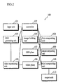
Fig. 2 is a block diagram showing the structure of an
image compositing apparatus according to the first embodiment
of the present invention.
In Fig. 2, an image compositing apparatus 100 includes
an input unit 101, a controller 102, an EPG generating unit
103, an image holding unit 104, a video reproducing unit 105,
a video plane 106, an OSD plane 107, a first compositing unit
108, a second compositing unit 109, a third compositing unit
110, and an output unit 111.
The input unit 101 includes a remote controller and front
panel buttons. Using the remote controller and the front panel
buttons, the user inputs instructions. More specifically,
the user inputs instructions to turn the image compositing
apparatus 100 ON and OFF, to switch channels, and to turn the
EPG (Electronic Program Guide) display ON and OFF.
Here, the "EPG" indicates a system for displaying program
tables, information on the program contents, and the like on
the TV screen. Also, the "EPG display" indicates the condition
in which a program table, for instance, is displayed on the'
TV screen. The EPG can be applied to searching for programs
on the EPG display screen by a genre or a cast. Also, an
EPG-compatible VCR can be easily programmed to record.
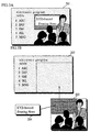
When the EPG display is ON, the image compositing
apparatus 100 displays a composite image 201 shown in Fig. 3A,
for instance.
The composite image 201 in Fig. 3A is composed of
components 202, 203, and 204 as shown in Fig. 3B. The component
202 is a graphical image indicating a program table, the
component 203 is a video image indicating the content of a
program of one channel, and the component 204 is a graphical
image indicating the title of the program shown by the
component 203. The components 202 and 204 are generated
according to the EPG information from the broadcasting
station.
As shown in Figs. 3A and 3B, the image compositing
apparatus 100 displays the component 202 while the EPG display
is ON. Also, the component 203 is displayed on the bottom right
and the component 204 on the upper left of the component 202.
The frame rate of a video image of the component 203 is dozens
of frames per second.
As has been described, the image compositing apparatus
100 has a function of generating and displaying a composite
image from a plurality of components including a plurality of
graphical images and one video image.
Here, explanations will be given using Figs. 3A and 3B
as necessary. Note that when not needed to be distinguished
from each other, the still and video image components are
referred to as just the "component".
The controller 102 controls all the elements of the image'
compositing apparatus 100. More specifically, when the user
instructs to turn the image compositing apparatus 100 ON, the
controller 102 has the video reproducing unit 105 reproduce
a program. When the user instructs to switch channels, the
controller 102 has the video reproducing unit 105 reproduce
another program. When the user instructs to turn the EPG
display ON, the controller controls the EPG generating unit
103, the video reproducing unit 105, the first compositing unit
108, the second compositing unit 109, and the third compositing
unit 110 so as to generate the composite image 201. The
processing relating to the EPG display will be described later.
The EPG generating unit 103 obtains and holds the EPG
information from the broadcasting station. The EPG
information includes layout information on the sizes,
positions, and overlaying order of components and graphical
image information on graphical image components. The
graphical image information, which corresponds to the image
contents of graphical image components, includes texts,
graphics data and the like. The EPG generating unit 103
generates a plurality of image files and one index file
according to the EPG information and stores the image files
and index file in the image holding unit 104. Then, the EPG
generating unit 103 extracts from the EPG information the size
and position of the video image component that is a part of
the EPG display screen. The extracted size and position are
output to the video reproducing unit 105.
The image files, which correspond to the components 202,
203, and 204, in Fig. 3B, includes the sizes, positions and
image data of the components. For the graphical image
component, the image data is generated by the EPG generating
unit 103 according to the graphical image information.
The index file, which is used for managing the plurality
of image files, includes a plurality of pieces of image
information. Each piece of image information corresponds to
a different image file. The plurality of pieces of image
information are arranged in the index file in the same order
as the overlaying order of components in Fig. 3A. Each piece
of image information includes an image type and a storage
position. The image type indicates whether the image of the
corresponding image file is a graphical image or a video image.
The storage position indicates the position of the beginning
of the corresponding image file in the image holding unit 104.
Here, an explanation of a specific example of the image
file and index file will be given with reference to Figs. 4
and 5.
Fig. 4 is a diagram for explaining the structure of the
image file.
In an image file 301 in Fig. 4, the first line indicates
the position, the second line the size, and the third and the
following lines the image data. The image data is composed
of a group of pixel data that correspond to the pixels of the
component. Each piece of the pixel data includes RGB
components that indicate the color of the pixel and an α value
that indicates the transparency of the pixel. Each α value
indicates a composition ratio of one of the images to a
composite of the image with images below the image in the
overlaying order of images. A storage position 302 at the left
of the image file 301 indicates the storage position of each
piece of the pixel data with reference to the position of the
beginning of the image file 301, "0000".
In the image file 301, the third line indicates the pixel
data corresponding to the pixel with the coordinates (0,0),
the fourth line the pixel data corresponding to the pixel with
the coordinates (1,0), and the fifth line the pixel data
corresponding to the pixel with the coordinates (2, 0). Here,
the coordinates (0,0) are located at the upper left corner of
the component. In this way, each piece of the pixel data
corresponds to a different pixel in the left-to-right and
top-to-bottom order.
The position indicates the coordinates of the component
in the composite image 201. The position is represented by
the x and y coordinates of the upper left corner of the component
by taking the upper left corner of the composite image 201 as
the origin.
The size indicates the height "H" and the width "W" of
the rectangular component. The height "H" and width "W" are
each represented in pixel units.
Each of the RGB components is represented by a value from
"0" to "255". When the three components are all "0", the pixel
color is black and when "255", white.
The α value, which is represented by a value from "0"
to "255", indicates the transparency when the pixel is overlaid
on another pixel, i.e., how degree the lower pixel passes
through the upper pixel.
More specifically, when a pixel "A" is combined with a
pixel "B" with the α value, a combined pixel "C" is
(αA+(255-α)B)/255. Here, the α value is from "0" to "255".
When the α value is "0", the pixel "A" is transparent, i.e.,
100% of the pixel "B" passes through the pixel "A". On the
other hand, when the α value is "255", the pixel "A" is opaque,
i.e., the pixel "B" does not pass through the pixel "A". In
this case, the combined pixel "C" is the same as the pixel "A".
Meanwhile, when the α value is "128", 50% of the pixel "B" passes
through the pixel "A", i.e., the combined pixel "C" has the
color that is a result of combining 50% of the pixel "A" with
50% of the pixel "B".
Actually, the pixels "A", "B", and "C" are represented
by the RGB components. The compositing results are calculated
for each of the components.
The EPG generating unit 103 sets the α values of the image
file of each of the components 202, 203, and 204 as follows.
The EPG generating unit 103 sets the α values of all the pixels
of the component 202 at "255". This is because the component
202 is positioned at the lowest layer in the composite image
201. Also, the EPG generating unit 103 sets the α values of
all the pixels of the component 203 at "192". For the component
204, the EPG generating unit 103 sets the α values of the pixels
corresponding to the characters at "255" and the α values of
the remaining pixels at "64".
Note that how to determine the RGB component values and
the α values is well known in the art and does not characterize
the present invention, so that no more detailed explanation
will be given here.
A component 303 in Fig. 4 is a diagram for showing the
correspondence between the image data and the component. As
shown in Fig. 4, each piece of the pixel data corresponds to
a different pixel in the left-to-right and top-to-bottom
order.
As has been described, the EPG generating unit 103
generates image files. Note that when generating an image file
corresponding to a video image component, the generating unit
103 sets all the RGB components at "0". More specifically,
when generating an image file for a video image component, the
generating unit 103 determines the position, size, and the α
values but no RGB components. This is because the RGB
components are not determined when an image file is generated
since video image components correspond to a program and are
transmitted from the broadcasting station in real time. The
RGB components of the image file corresponding to a video image
component are determined by the video reproducing unit 105,
which will be described later.
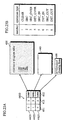
Fig. 5 shows an example of the index file. An index file
410 in Fig. 5 includes image information 421, 422, and 423.
The image information 422 is overlaid on the image information
421, and the image information 423 is overlaid on the image
information 422. More specifically, the image information
421 corresponds to the component 202 that is positioned at the
lowest layer, the image information 422 corresponds to the
component 203 at the next layer, and the image information 423
corresponds to the component 204 at the uppermost layer. The
values in a column 411 indicate the image types of the
components. The value "0" indicates the graphical image,
while the value "1" the video image. On the other hand, the
values in a column 412 indicates the storage positions.
Meanwhile, images 430, 440, and 450 correspond to the
components 202, 203, and 204, respectively. The images 430,
440 and 450 show the image data in the corresponding image files
in the form of image. Here, the image 440 shows that all the
RGB components of the image data corresponding to the component
203 are "0".
The image holding unit 104 is composed of a memory, a
hard disk, or the like. The image holding unit 104 holds the
image file and index file that have been generated by the EPG
generating unit 103.
The video reproducing unit 105 receives the program from
the broadcasting station and decodes the program. Then, the
video reproducing unit 105 reproduces video images at the frame
rate of dozens of frames per second and stores the video image
data on the video plane 106 in order. When storing the video
image data, the video reproducing unit 105 determines the
layout with reference to the composite image 201 according to
the position and size that have been input from the EPG
generating unit 103. By doing so, the video reproducing unit
105 stores the RGB components in an area on the video plane
106 according to the layout.
The video plane 106 is composed of memory or the like.
The video plane 106 holds video image data that has been stored
by the video reproducing unit 105 and a composite α value that
has been stored by the second compositing unit 109. A
composite α value indicates the transparency of one of a
plurality of pixels when the plurality of pixels are combined.
More specifically, the composite α values held by the video
plane 106 indicate the transparency of the pixels of the video
image component when the plurality of components are
composited.
Fig. 6 shows the structure of a video image file. As
shown in Fig. 6, video image data 501 is composed of a group
of pixel data. Each piece of the pixel data is composed of
RGB components and a composite α value. An image 502 is a
diagram for showing the correspondence between each of the
pixel data and a different pixel position in the image.
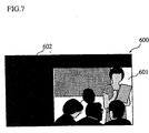
Fig. 7 shows the pixel data in the video image data 501
in the visual form. As shown in Fig. 7, an image 600
corresponding to the video image data 501 is composed of an
area 601 corresponding to the component 203 and an area 602
corresponding to the remaining part. The image 600 has the
same height and width as the composite image 201. The video
plane 106 receives the RGB components of the area 601 from the
video reproducing unit 105 and the α values from the second
compositing unit 109. Meanwhile, the video plane 106 holds
"0" as the RGB components and the α values of the area 602 in
advance. The RGB components of the area 601 are updated at
the rate of dozens of frames per second in accordance with the
reproduction rate of the video reproducing unit 105.
The OSD plane 107 is composed of a memory or the like.
The OSD plane 107 holds first composite image data that has
been output from the first compositing unit 108.
Fig. 8 shows the data structure of first composite image
data 701. The first composite image data 701 is composed of
a group of RGB components. The first composite image data 701
corresponds to the result of compositing the components 202
and 204, i.e., the compositing result of the graphical image
components. The compositing will be described later.
An image 702 is a diagram for showing the correspondence
between each set of the RGB components and a different pixel
position in the image. As shown in Fig. 8, each set the RGB
components corresponds to a different pixel in the left-to-right
and top-to-bottom order. The image 702 has the same
height and width as the composite image 201 in pixel units.
The first compositing unit 108 combines the image data
of the plurality of image files that have been stored in the
image holding unit 104 to generate the first composite image
data. The first composite image data is stored on the OSD plane
107. This processing is referred to as the "first compositing
processing".
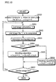
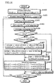
Fig. 9 is a flowchart showing the first compositing
processing.
To begin with, the first compositing unit 108 initializes
the OSD plane 107 (step S800). More specifically, all the
areas for RGB components are set to be "0" on the OSD plane
107.
Next, the first compositing unit 108 repeats the
operations at steps S801 to S807 to composite graphical image
components in turn in the bottom-to-top order.
At step S801, the first compositing unit 108 reads image
information "i" from the index file in the image holding unit
104. Here, the letter "i" is a variable that indicates a number
assigned to a component. Numbers are assigned to the overlaid
components from the bottom to the top in the ascending numeric
order. The image information and the image file corresponding
to a component "i" are referred to as the "image information
"i"" and the "image file "i"". In this flowchart, the initial
value of "i" is set to "0" and the increment is "1".
Then, the first compositing unit 108 reads from the image
holding unit 104 the image file "i" that has been stored in
the storage position indicated by the image information "i"
(step S802).
The first compositing unit 108 reads the size and the
position to determine an area on the OSD plane 107 where the
component "i" overlaps another component (step S803).
The first compositing unit 108 judges whether the image
type indicated by the image information "i" is video image or
graphical image (step S804).
When the image type is graphical image, the first
compositing unit 108 performs the α blending algorithm for the
RGB components of the image file "i" and the RGB components
in the overlapping area on the OSD plane 107 (step S805). The
α blending algorithm is given below.
R(x,y) = αi(x,y)*Ri(x,y)+(1-αi(x,y))*R(x,y)
G(x,y) = αi(x,y)*Gi(x,y)+(1-αi(x,y))*G(x,y)
B(x,y) = αi(x,y)*Bi(x,y)+(1-αi(x,y))*B(x,y)
In these equations, the terms R(x,y), G(x,y), and B(x,y)
on the left sides indicate RGB components that are to be newly
obtained. The terms Ri(x,y), Gi(x,y), Bi(x,y), and αi(x,y)
indicate RGB components and an α value of the image file "i".
On the other hand, the terms R(x,y), G(x,y), and B (x,y) on the
right sides indicate RGB components that are held in the
overlapping area on the OSD plane 107. More specifically, the
value R(x,y) on the left side is obtained as follows. The
values Ri(x,y) and R(x,y) are weighted with values αi and 1-αi,
respectively. The sum of the weighting results is the value
R(x,y) on the left side. The values G(x,y) and B(x,y) are
obtained in the same manner. The first compositing unit 108
stores the newly obtained RGB components R(x,y), G(x,y), and
B(x,y) on the OSD plane 107.
On the other hand, when it is judged that the image type
is video image at step S804, the first compositing unit 108
performs arithmetic operations according to the equations
given below using the α values of the image file "i" and the
RGB components in the overlapping area on the OSD plane 107
(step S806).
R(x,y) = (1-αi(x,y))*R(x,y)
G(x,y) = (1-αi(x,y))*G(x,y)
B(x,y) = (1-αi(x,y))*B(x,y)
In these equations, the terms R(x,y), G(x,y), and B(x,y)
on the left sides indicate RGB components that are to be newly
obtained. The term αi(x,y) indicates an α value of the image
file "i". On the other hand, the terms R(x,y), G(x,y), and
B(x, y) on the right sides indicate RGB components that are held
in the overlapping area on the OSD plane 107. More
specifically, the value R(x,y) on the left side is obtained
by weighting the R (x, y) on the right side with a value 1-αi(x,y).
The values G(x,y) and B(x,y) are obtained in the same manner.
When the first terms on the right sides of the equations
in Equation Group 2 are set as "0", the equations in Equation
Groups 2 and 3 become the same.
In the first terms on the right sides of the equations
at step S805, the RGB components of the image file are weighted
with the value α. Accordingly, the RGB components of the video
image are not weighted with the value α in the equations at
step S806.
The first compositing unit 108 stores the RGB components
R(x,y), G(x,y), and B(x,y) that have been calculated at step
S805 or S806 on the OSD plane 107.
When the first compositing unit 108 has performed the
processing for all the image files as has been described, the
first compositing processing is completed (step S807).
As a result of the first compositing processing, the
result of the compositing the graphical image components is
held on the OSD plane 107.
The second compositing unit 109 calculates the composite
α values for the video image component and stores the
calculated composite α values to perform "second compositing
processing".
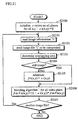
Fig. 10 is a flowchart showing the second compositing
processing.
To begin with, the second compositing unit 109
initializes the composite α values on the video plane 106 (step
S900). More specifically, all the areas for composite α values
are set to be "0" on the video plane 106. The composite α values,
as a result of the processing in Fig. 10, retain the α composite
values for the video image component.
Next, the second compositing unit 109 repeats the
operations at steps S901 to S907.
At step S901, the second compositing unit 109 reads image
information "i" from the index file in the image holding unit
104. Here, the letter "i" is a variable that indicates a number
assigned to a component. Numbers are assigned to the overlaid
components from the bottom to the top in the ascending numeric
order. The image information and the image file corresponding
to a component "i" are referred to as the "image information
"i"" and the "image file "i"". In this flowchart, the initial
value of "i" is set to "0" and the increment is "1".
Then, the second compositing unit 109 reads from the'
image holding unit 104 the image file "i" that has been stored
in the storage position indicated by the image information "i"
(step S902).
The second compositing unit 109 reads the size and the
position to determine an area on the video plane 106 where the
component "i" overlaps another component (step S903).
The second compositing unit 109 judges whether the image
type indicated by the image information "i" is video image or
graphical image (step S904).
When the image type is graphical image, the second
compositing unit 109 calculates newly composited α value based
on the composited α value of the image file "i" and the
composited α value in the overlapping area on the video plane
106 (step S905). The equation for this calculation is given
below.
α(x,y) = (1-αi (x,y))*α(x,y)
In this equation, the term α(x,y) on the left side
indicates a composite α value that is to be newly obtained.
The term αi(x,y) indicates an α value of the image file "i".
On the other hand, the term α(x,y) on the right side indicates
an α value that is held in the overlapping area on the video
plane 106.
The second compositing unit 109 stores the newly obtained
composite α values α(x,y) on the video plane 106.
On the other hand, when it is judged that the image type
is video image at step S904, the second compositing unit 109
performs arithmetic operations according to the equation given
below (step S906).
α(x,y) = αi(x,y)
In this equation, the term α(x,y) on the left side
indicates an α value that is to be newly obtained. The term
αi(x,y) on the right side indicates an α value of the image
file "i". More specifically, the α value αi (x, y) is the α value
that is to be newly obtained.
The second compositing unit 109 stores the α values
α(x,y) that have been calculated at step S905 or S906 on the
video plane 106.
When the second compositing unit 109 has performed the
processing for all the image files as has been described, the
second compositing processing is completed (step S907). As
a result, the composite α values are stored on the video plane
106.
When receiving normal reproduction instructions from the
controller 102, the third compositing unit 110 outputs to the
output unit 111 the RGB components that have been held on the
video plane 106. Also, when receiving the EPG display
instructions from the controller 102, the third compositing
unit 110 performs "third compositing processing" to composite
the RGB components stored on the video plane 106 with the RGB
components of the first composite image data stored on the OSD
plane 107. Then, the third compositing unit 110 outputs the
composite image to the output unit 111.
The third compositing processing is indicated by the
equations given below.
R(x,y) = α(x,y)*Rv(x,y)+Ro(x,y)
G(x,y) = α(x,y)*Gv(x,y)+Go(x,y)
B(x,y) = α(x,y)*Bv(x,y)+Bo(x,y)
Here, the terms R(x,y), G(x,y), and B(x,y) indicate the
RGB components of each of the pixels that are to be output to
the output unit 111 as a result of the third compositing
processing. The terms α(x,y), Rv(x,y), Gv(x,y), and Bv(x,y)
indicate each of the composite α values and each set of the
RGB components of the video image data that is stored on the
video plane 106. Meanwhile, terms Ro(x,y), Go(x,y), and
Bo(x,y) indicate each set of the RGB components of the first
composite image data.
Accordingly, the third compositing unit 110 calculates
the sum of RGB components of the first composite image data
held on the OSD plane 107 and the product of RGB components
and a composite α value of the video image data held on'the
video plane 106 for each frame in the video reproduction.
The output unit 111 is composed of a CRT (Cathode-Ray
Tube) or the like. The output unit 111 receives the RGB
components that have been output from the third compositing
unit 110 and displays the received RGB components.
(Operations)
Here, an explanation of the operations by the image
compositing apparatus 100 will be given below.
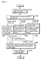
Fig. 11 is a chart for explaining the flow of the
operations by the image compositing apparatus 100 at the time
of the EPG display.
In Fig. 11, operations by elements of the image
compositing apparatus 100 are indicated in the rectangles and
the data flow by the arrows.
When received by the input unit 101 (step S1001), the
EPG display instructions is sent to the other elements via the
controller 102. When receiving the EPG instructions, the EPG
generating unit 103 generates image files and an index file
according to the EPG information that has been broadcast. The
generated image files and index file are stored in the image
holding unit 104. Also, the EPG generating unit 103 informs
the video reproducing unit 105 of the position and size of the
video image component that has been obtained when generating
the image files (step S1002).
The first compositing unit 108 combines the RGB
components in the overlapping areas in graphical image
components stored in the image holding unit 104. The combined
RGB components are stored on the OSD plane 107 (step S1003).
The second compositing unit 109 calculates the composite
α values for the video image component according to the α values
of the image files that have been stored in the image holding
unit 104. The calculated composite α values are stored on the
video plane 106 (step S1004).
The video reproducing unit 105 reproduces the video image
and stores the video image data on the video plane 106 according
to the layout indicated by the size and position that have been
obtained from the EPG generating unit 103 (step S1005).
The third compositing unit 110 weighted the RGB
components of the video image component with the composite α
values. Then, the RGB components of the first composite image
data are added to the weighted RGB components to obtain the
RGB components of the composite image. The obtained RGB
components of the composite image are output to the output unit
111 (step S1006).
The output unit 111 displays the composite image RGB
components from the third compositing unit 110 (step S1007).
In Fig. 9, operations at steps S1003, 1004, 1005, and
1006 are performed in parallel. The operation at step S1006
is performed at the same rate as the reproduction rate of the
video image data at step S1005.
Supplemental remarks will be given below on the
compositing of video and graphical images, which is an
important feature of the present invention.
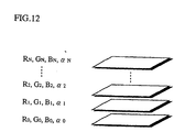
Fig. 12 shows a component group, which is composed of
N+1 video and/or graphical image components. Each of the
components has RGB components and an α value an shown in Fig.
12. Note that the α value is α0 = 1.0 for the component
positioned at the lowest layer of the layer. The RGB
components of the composite image of the component group 1101
is obtained according to the equations given below.
R = Σ(βi*Ri)
i = 0 to N
G = Σ(βi*Gi)
i = 0 to N
B =Σ(βi*Bi)
i = 0 to N
Note that
βi = αiΠ (1-αj) 1
j = i+1 to N
In these equations, the term "βi" indicates the
composition ratio of each of the pixels of the component "i"
to the final composite image, i.e., the composite α value of
each of the pixels. In this specification, the β value is
referred to as the "contribution degree".
According to the present invention, when one of the
components is a video image, arithmetic operations are
performed as follow. First, the other components, i.e., the
graphical image components are composited using α values.
Then, the video image component is added to the result of the
compositing of the graphical image components. Each of the
graphical image components is represented by an image file
including a size and a position. Composited on the OSD plane
107, the graphical image components can be efficiently
composited with a small amount of memory such as the OSD plane
107, i.e., one OSD plane.
Accordingly, the processing can be efficiently performed
with a small amount of memory, i.e., one OSD plane for graphical
image and one video plane for video image.
Instead, if the video and graphical image components are
composited in turn in the order of layer, the contribution
degree of each of the pixels for all the components need to
be calculated and stored on the memory. This requires a large
amount of memory and not efficient.
Also, the arithmetic operation of the contribution
degrees for each of the components includes many
multiplications. More specifically, N*(N-1)/2
multiplications by N^2 orders of magnitude are required for
N+1 components.
The present invention solves these problems. More
specifically, sequential calculations with a few memories and
multiplications by N orders are realized. The relationship
between the elements and the arithmetic operations are as
follows. The first compositing unit 108 deals with the
addition of the graphical image components, the second
compositing unit 109 calculation of the contribution degrees
of the video image, and the third compositing unit 110 the
addition of the video image.
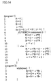
Fig. 13 shows a program for the arithmetic operations
of the present invention written in the form of the C language.
This program focuses on one pixel. The letters "R", "G", and
"B" indicate the RGB components of one pixel on the OSD plane,
and the letter "α" the composite α value of a pixel of a video
image corresponding to the pixel. Meanwhile, the letters "Ri",
"Gi", "Bi", and "αi" indicate the RGB components and the α value
of a pixel of the "i"th component corresponding to the pixel,
the letters "Rv", "Gv", and "Bv" the RGB components of a pixel
of the video image corresponding to the pixel.
The first to fourth lines indicate the initialization
processing, the fifth to 17th lines the addition of the
graphical images, and the remaining lines the addition of the
video image. Meanwhile, the seventh, eighth, ninth, 12th,
13th, and 14th indicate the arithmetic operations performed
by the first compositing unit 108. Here, in the equations for
compositing the video image, the RGB components are
substantially set to be "0". The 10th and 15th lines indicate
the arithmetic operations performed by the second compositing
unit 109 to calculate the composite α value of the video image.
The fifth, sixth, 11th, 16th, and 17th lines are commonly
performed by the first compositing unit 108 and the second
compositing unit 109. Meanwhile, the 18th to 20th lines
indicate the arithmetic operations performed by the third
compositing unit 110. Here, the 18th, 19th, and 20th lines
may be performed by different threads in parallel. Also, the
18th to 20th lines may be an endless loop.
Fig. 14 shows the programs that realize the program shown
in Fig. 13. The program in Fig. 13 is divided into programs
1 and 2. The output in the program 2 is an endless loop. The
programs 1 and 2 can be performed in parallel. In this case,
the state and process of overlaying can be displayed.
Fig. 15 is a block diagram showing the structure of an
image compositing apparatus according to the second embodiment
of the present invention.
In Fig. 15, an image compositing apparatus 200 includes
the input unit 101, a controller 1500, the EPG generating unit
103, the image holding unit 104, the video reproducing unit
105, the video plane 106, an OSD plane 1501, a fourth
compositing unit 1502, a fifth compositing unit 1503, and the
output unit 111. Note that the elements that have the same
reference numbers as of the image compositing apparatus 100
have the same functions. The following explanation will focus
on the elements that have the different reference numbers from
the image compositing apparatus 100.
The controller 1500 controls all the elements of the
image compositing apparatus 200. More specifically, when the
user instructs to turn the image compositing apparatus 200 ON,
the controller 1500 has the video reproducing unit 105
reproduce a program. When the user instructs to switch
channels, the controller 102 has the video reproducing unit
105 reproduce another program. When the user instructs to turn
the EPG display ON, the controller controls the EPG generating
unit 103, the video reproducing unit 105, the fourth
compositing unit 1502, the fifth compositing unit 1503, and
the like so as to generate a composite image.
The OSD plane 1501 is composed of a memory or the like.
The OSD plane 1501 holds the RGB components and the α values
that has been output from the fourth compositing unit 1502.
The OSD plane 1501 holds the RGB components and the α values
corresponding to the pixels of image.
When receiving instructions from the controller 1500,
the fourth compositing unit 1502 composites the image data of
the plurality of image files held in the image holding unit
104. In the end, the fourth compositing unit 1502 generates
fourth composite image data and stores the fourth composite
image data on the OSD plane 1501. This processing is referred
to as the "fourth compositing processing" in this
specification.
Fig. 16 is a flowchart showing the fourth compositing
processing.
To begin with, the fourth compositing unit 1502 sets all
the areas for RGB component on the OSD plane 1501 and for α
value on the video plane 106 to be "0" (steps S1600 and S1601).
Next, the fourth compositing unit 1502 repeats the
operations at steps S1602 to S1612. More specifically, the
fourth compositing unit 1502 composites graphical image
components in turn in the bottom-to-top order. Also, the
fourth compositing unit 1502 blends α values together for the
video image component and stores the blended α values on the
video plane 106.
At step S1602, the fourth compositing unit 1502 reads
the image information "i" from the index file in the image
holding unit 104. Here, the letter "i" is a variable that
indicates a number assigned to a component. Numbers are
assigned to the overlaid components from the bottom to the top
in the ascending numeric order. The image information and the
image file corresponding to a component "i" are referred to
as the "image information "i"" and the "image file "i"". In
this flowchart, the initial value of "i" is set to "0" and the
increment is "1".
Then, the fourth compositing unit 1502 reads from the
image holding unit 104 the image file "i" that has been stored
in the storage position indicated by the image information "i"
(step S1603).
The fourth compositing unit 1502 reads the size and the
position to determine an area on the OSD plane 107 where the
component "i" overlaps another component (step S1604).
The fourth compositing unit 1502 judges whether the image
type indicated by the image information "i" is video image or
graphical image (step S1605).
When the image type is video image, the fourth
compositing unit 1502 copies the α values of the image file
"i" on the video plane 106 (step S1611).
On the other hand, when the image type is graphical image,
the fourth compositing unit 1502 judges whether all the α
values held on the video plane 106 are "0" (step S1606). By
doing so, the following processing is different according to
whether a video image is included at the lower layer than the
graphical image.
When it is judged that all the α values held on the video
plane 106 are "0" at step S1606, the fourth compositing unit
1502 copies the α values of the image file "i" on the OSD plane
1501 (step S1609).
On the other hand, when it is judged that the α values
held on the video plane 106 are not all "0", i.e., when at least
one α value is not "0" on the video plane 106, at step S1606,
the fourth compositing unit 1502 calculates new α values
according to the equation given below using the α values held
on the video plane 106 and the α values of the image file "i".
Also, the fourth compositing unit 1502 stores the newly
obtained α values on the OSD plane 1501 (step S1607).
αosd (x, y) = αi(x,y) 1-αv(x,y)*(1-αi(x,y))
In this equation, the term αosd(x,y) on the left side
indicates an α value that is to be newly obtained. On the right
side, the term αi(x,y) indicates an α value of the image file
"i" and the term αv(x,y) an α value held on the video plane
106.
Moreover, the fourth compositing unit 1502 calculates
α values for the video image according to the equation given
below. The calculated α values are stored in the area for α
value on the video plane 106 (step S1608).
αv(x,y) = αv(x,y)*(1-αi(x,y))
In this equation, the term αv(x,y) on the left side
indicates an α value that is to be newly stored on the video
plane 106. On the right side, the term αv(x,y) indicates an
α value that has been stored on the video plane 106 before the
storage of the newly obtained α value and the term αi(x,y)
indicates an α value of the image file "i".
The fourth compositing unit 1502 performs the α blending
algorithm for the RGB components of the image file "i" and the
RGB components in the overlapping area on the OSD plane 107.
The result of the α blending algorithm is stored on the OSD
plane 1501 (step S1610). The α blending algorithm is given
below.
R(x,y) = αosd(x,y)*Ri(x,y)+(1-αosd(x,y))*R(x,y)
G(x,y) = αosd(x,y)*Gi(x,y)+(1-αosd(x,y))*G(x,y)
B(x,y) = αosd(x,y)*Bi(x,y)+(1-αosd(x,y))*B(x,y)
In these equations, the terms R(x,y), G(x,y), and B(x,y)
on the left sides indicate RGB components that are to be newly
obtained. On the right sides, the terms R (x,y), G (x,y), B(x,y),
and αosd indicate RGB components and an α value held on the
OSD plane 1501. Also, the terms Ri(x,y), Gi(x,y), and Bi(x,y)
on the right sides indicate RGB components of the image file
"i".
The fourth compositing unit 1502 performs the processing
from steps S1602 to S1612 as has been described for all the'
image files to complete the fourth compositing processing
(step S1612).
As a result of the fourth compositing processing, the
result of the compositing the graphical image components is
held on the OSD plane 1501, the composite α values of the video
image component in the area for α value on the video plane 106.
When receiving normal reproduction instructions from the
controller 1500, the fifth compositing unit 1503 outputs to
the output unit 111 the RGB components that have been held on
the video plane 106.
Also, when receiving the EPG display instructions from
the controller 1500, the fifth compositing unit 1503 performs
"fifth compositing processing" to composite the RGB components
and α values of the video image data stored on the video plane
106 with the RGB components of the fourth composite image data
stored on the OSD plane 1501. Then, the fifth compositing unit
1503 outputs the compositing result to the output unit 111.
The fifth compositing processing is indicated by the
equations given below.
R(x,y) = α(x,y)*Rv(x,y)+Ro(x,y)
G(x,y) = α(x,y)*Gv(x,y)+Go(x,y)
B(x,y) = α(x,y)*Bv(x,y)+Bo(x,y)
Here, the terms R(x,y), G(x,y), and B(x,y) indicate the
RGB components of each of the pixels that are to be output to
the output unit 111 as a result of the fifth compositing
processing. The terms α(x,y), Rv(x,y), Gv(x,y), and Bv(x,y)
indicate each of the composite α values and each set of the'
RGB components of the video image data that is stored on the
video plane 106. Meanwhile, terms Ro(x,y), Go(x,y), and
Bo(x,y) indicate each set of the RGB components of the fourth
composite image data.
Accordingly, the fifth compositing unit 1503 composites
a frame of video images with the fourth composite image data
whenever the video image frame is updated.
Here, an explanation of the operations by the image
compositing apparatus 200 will be given below.
Fig. 17 is a chart for explaining the flow of the
operations by the image compositing apparatus 200 at the time
of EPG display. In Fig. 17, operations by elements of the image
compositing apparatus 200 are indicated in the rectangles and
the data flow by the arrows. Note that at the steps in the
flowchart in Fig. 17 that have the same reference numbers as
in the flowchart in Fig. 11, the same operations as in Fig.
11 are performed.
When received by the input unit 101 (step S1001), the
EPG display instructions is sent to the other elements via the
controller 1500. When receiving the EPG instructions, the EPG
generating unit 103 generates image files and an index file
according to the EPG information that has been broadcast. The
generated image files and index file are stored in the image
holding unit 104. Also, the EPG generating unit 103 informs
the video reproducing unit 105 of the position and size of the
video image component that has been obtained when generating
the image files (step S1002).
The fourth compositing unit 1502 combines the RGB
components in the overlapping areas in graphical image
components stored in the image holding unit 104. The combined
RGB components are stored on the OSD plane 1501. Also, the
fourth compositing unit 1502 calculates the composite α values
for the video image and stores the calculated composite α
values on the video plane 106 (step S1701).
The video reproducing unit 105 reproduces the video image
and stores the video image data on the video plane 106 according
to the layout indicated by the size and position that have been
obtained from the EPG generating unit 103 (step S1005).
The fifth compositing unit 1503 weighted the RGB
components of the video image component with the composite α
values. Then, the RGB components of the fourth composite image
data are added to the weighted RGB components to obtain the
RGB components of the composite image. The obtained RGB
components of the composite image are output to the output unit
111 (step S1702).
The output unit 111 displays the composite image RGB
components from the fifth compositing unit 1503 (step S1007).
In Fig. 17, operations at steps S1702, 1005, and 1701
are performed in parallel.
In the compositing method according to the present
embodiment, the order of any adjacent two components in the
component layer are switched when composited as shown in Fig.
18. In this case, the α values of the switched two components
are updated according to the equations given below.
In the following equations, each of the α value of the
lower component "i" after the switch is indicated by the term
αi+1' and each of the α values of the upper component "i+1"
the term αi'.
αi+1' = αi+1 1-αi(1-αi+1)
αi' = αi (1-αi+1)
Here, Equation Group 12 is obtained as follows.
Suppose that the α values of the components "i" and "i+1"
before the switch are αi and αi+1, the contribution degrees
βi and βi+1 of pixels of the components "i" and "i+1" before
the switch to the final composite image are obtained according
to the equations given below.
βi = αiΠ (1-αj) 1
j = i+1 to N
βi+1 = αi+1*Π(1-αj) 2
j = i+2 to N
On the other hand, the contribution degrees βi' and βi+1'
of pixels of the components "i" and "i+1" after the switch to
the final composite image are obtained according to the
equations given below.
βi+1' = αi+1'*(1-αi')Π(1-αj) 3
j = i+2 to N
βi ' = αi'*Π(1-αj) 4
j = i+2 to N
In order to have the same compositing result before
and after the switch, it is enough that the results of the
equations 1 ○ and 4 ○ are the same and the equations 2 ○ and 3 ○ also
the same. More specifically, when the following equations are
solved for the α values αi' and αi+1, the results of the
equations in Equation Group 12.
αiΠ (1-αj) = αi'*II(1-αj)
j = i+1 to N j = i+2 to N
αi+1*Π(1-αj) = αi+1'*(1-αi') Π(1-αj)
j = i+2 to N j = i+2 to N
By switching the video image component and a graphical
image component using this law so that the video image
component is positioned at the uppermost as shown in Fig. 19,
all the graphical image components are composited together and
then the video image component is composited with the composite
graphical image components.
As shown in the flowchart in Fig. 16, the fourth
compositing unit 1502 efficiently calculates the α values
necessary to switch the adjacent components. Also, the fourth
compositing unit 1502 efficiently composites graphical image
components and stores the compositing result on the OSD plane
1501. Meanwhile, the fifth compositing unit 1503 composites
the OSD plane 1501 with the video plane 106.
Fig. 20 is a block diagram showing the structure of an
image compositing apparatus according to the third embodiment
of the present invention.
In Fig. 20, an image compositing apparatus 300 includes
the input unit 101, a controller 2000, an EPG generating unit
2003, the image holding unit 104, a video reproducing unit 2001,
a video plane 2002, the OSD plane 107, a sixth compositing unit
2004, a seventh compositing unit 2005, an eighth compositing
unit 2006, and the output unit 111. With this structure, the
image compositing apparatus 300 composites a plurality of
video image components with a plurality of graphical image
components. Note that the elements that have the same
reference numbers as of the image compositing apparatuses 100
and 200 have the same functions. The following explanation
will focus on the elements that have the different reference
numbers from the image compositing apparatuses 100 and 200.
The controller 2000 controls all the elements of the
image compositing apparatus 300. More specifically, when the
user instructs to turn the image compositing apparatus 300 ON,
the controller 2000 has the video reproducing unit 2001
reproduce a program. When the user instructs to switch
channels, the controller 2000 has the video reproducing unit
2001 reproduce another program. When the user instructs to
turn the EPG display ON, the controller 2000 controls the EPG
generating unit 2003, the video reproducing unit 2001, the
sixth compositing unit 2004, the seventh compositing unit 2005,
the eighth compositing unit 2006, and the like so as to generate
a composite image.
The video reproducing unit 2001 includes a plurality of
reproducing units, i.e., a first reproducing unit, a second
reproducing unit, ..., an Nth reproducing unit. Each of the
reproducing units receives a different program. Also, the
first to Nth reproducing units decode the received programs,
reproduce the video images at dozens of frames per second, and
store the video image data on the video plane 2002 while
updating the video image data in frame units. When the video
image data is stored on the video plane 2002, the video
reproducing unit 2001 determines the layout of the video images
on the final composite image according to the positions and
sizes that have been input by the EPG generating unit 2003.
Also, the video reproducing unit 2001 stores the RGB components
of the video images on the corresponding areas on the video
plane 2002.
The video plane 2002 includes a plurality of planes, i.e.,
a first plane, a second plane, ..., and an Nth plane. Each
of the planes is composed of a memory or the like. Each one
of the planes corresponds to a different one of the plurality
of reproducing units in the video reproducing unit 2001. The
planes hold the video image data from the reproducing units
and the composite α values from the seventh compositing unit
2005.
The EPG generating unit 2003 obtains the EPG information
for the EPG display composed of a plurality of video image
components and graphical image components from the
broadcasting station. Also, the EPG generating unit 2003
generates a plurality of image files and one index file
according to the EPG information. The image files and the
index file are stored in the image holding unit 104.
Furthermore, the EPG generating unit 2003 extracts from the
EPG information the sizes and positions of the plurality of
video image components that are to be composited into the EPG
display image. The extracted sizes and positions are output
to the video reproducing unit 2001.
The EPG generating unit 2003 is almost the same as the
EPG generating unit 103. The difference is that the EPG
generating unit 2003 is capable of dealing with a plurality
of video image components.
The sixth compositing unit 2004 composites the image data
of the plurality of image files held in the image holding unit
104. Then, the sixth compositing unit 2004 generates sixth
composite image data and stores the sixth composite image data
on the OSD plane 107. This processing is referred to as the
"sixth compositing processing" in this specification. The
sixth compositing processing is almost the same as the first
compositing processing in the first embodiment shown in Fig.
9. The difference is that the operation at step S806 is
repeated a plurality of times in the sixth compositing
processing so as to deal with a plurality of video images.
When receiving instructions from the controller 2000,
the seventh compositing unit 2005 calculates composite α
values for each of the plurality of video image components.
Also, the seventh compositing unit 2005 stores the calculated
α values for each of the video image components on a different
corresponding planes. This processing is referred to as the
"seventh compositing processing" in this specification.
Fig. 21 is a flowchart showing the seventh compositing
processing.
To begin with, the seventh compositing unit 2005
initializes the composite α values on the video plane 2002
(step S2100). More specifically, the areas for α values in
the planes are set to be "0" on the video plane 2002.
Next, the seventh compositing unit 2005 repeats the
operations at steps S2101 to S2107.
At step S2101, the seventh compositing unit 2005 reads
image information "i" from the index file in the image holding
unit 104. Here, the letter "i" is a variable that indicates
a number assigned to a component. Numbers are assigned to the
overlaid components from the bottom to the top in the ascending
numeric order. The image information and the image file
corresponding to a component "i" are referred to as the "image
information "i"" and the "image file "i"". In this flowchart,
the initial value of "i" is set to "0" and the increment is
"1".
Then, the seventh compositing unit 2005 reads from the
image holding unit 104 the image file "i" that has been stored
in the storage position indicated by the image information "i"
(step S2102).
The seventh compositing unit 2005 reads the size and the
position of the image file "i" to determine an area on the video
plane 2002 where the component "i" overlaps another component
(step S2103).
The seventh compositing unit 2005 judges whether the
image type indicated by the image information "i" is video
image or graphical image (step S2104).
When the image type is video image, the seventh
compositing unit 2005 copies the α values of the image file
"i" in the area for α value on the "k"th plane on the video
plane 2002 (step S2105). The equation for the operation at
step S2105 is given below.
βk(x,y) = αi(x,y)
In this equation, the term αi(x,y) on the left side
indicates a value that is to be stored in the area for α value
on the "k"th plane on the video plane 2002. The term αi(x,y)
indicates an α value of the image file "i". The value of "k"
is "1" to "N" and is incremented by "1" whenever the operation
at step S2105 is performed.
After that, the seventh compositing unit 2005 updates
the value of βm(x,y) for the area for α value on the "m"th plane,
which is different from the "k"th plane, on the video plane
2002 using the equation given below.
βm(x,y) = (1-αi(x,y))*βm(x,y)
Here, the term βm(x,y) on the left side indicates each
of the values that are to be stored in the area for α value
on the "m"th plane. The value of "m" is from "1" to "N"
excluding "k".
Accordingly, the arithmetic operations performed at step
S2105 and S2106 is the same as arithmetic operation 1 ○ in
Equation Group 7. As a result of the arithmetic operations
at step S2105 or S2106, the composition ratio of each of the
pixels of the video image components to the final composite
image, i.e., each of the composite α values, is calculated.
When the seventh compositing unit 2005 has performed the
processing for all the image files as has been described, the
seventh compositing processing is completed (step S2107). As
a result, the composite α values for each of the video image
components are stored on the corresponding plane on the video
plane 2002.
When receiving the EPG display instructions from the
controller 2000, the eighth compositing unit 2006 performs
"eighth compositing processing" to composite the RGB
components on the planes on the video plane 2002 with the RGB
components on the OSD plane 107. Then, the eighth compositing
unit 2006 outputs the composite image to the output unit 111.
When the number of the video image components is "N",
the eighth compositing processing is indicated by the
equations given below.
R(x,y) = β1(x,y)*Rv1(x,y)+β2(x,y)*Rv2(x,y)+ ...
+βN(x,y)*RvN(x,y)+Ro(x,y)
G(x,y) = β1(x,y)*Gv1(x,y)+β2(x,y)*Gv2(x,y)+ ...
+βN (x, y)*GvN (x, y) +Go (x, y)
B(x,y) = β1(x,y)*Bv1(x,y)+β2(x,y)*Bv2(x,y)+ ...
+βN(x,y)*BvN(x,y)+Bo(x,y)
Here, the terms R(x,y), G(x,y), and B(x,y) indicate RGB
components of each of the pixels that are to be output to the
output unit 111. The terms β1(x,y), Rv1(x,y), Gv1(x,y), and
Bv1(x,y) indicate each of the composite α values and each set
of the RGB components of the video image data that is stored
on the first plane on the video plane 2002. Accordingly, the
terms β2(x,y), Rv2(x,y), Gv2(x,y), and Bv2(x,y) indicate each
of the composite α values and each set of the RGB components
of the video image data that is stored on the second plane on
the video plane 2002, and the terms βN (x,y), RvN(x,y), GvN(x,y),
and BvN(x,y) each of the composite α values and each set of
the RGB components of the video image data that is stored on
the Nth plane on the video plane 2002. Meanwhile, the terms
Ro(x,y), Go(x,y), and Bo(x,y) indicate each set of the RGB
components stored on the OSD plane 107.
The operations by the image compositing apparatus 300,
which has the structure that has been described, are almost
the same as the operations by the image compositing apparatus
100 in Fig. 11.
The operations by the image compositing apparatus 300
are different from those by the image compositing apparatus
100 in the following points.
The operation at step S1002 is performed by the EPG
generating unit 2003. More specifically, the EPG generating
unit 2003 informs the video reproducing unit 2001 of the
positions and sizes of not one video image component but a
plurality of video image components.
Also, the operation at step S1003 is performed by the
sixth compositing unit 2004.
The operation at step S1004 is performed by the seventh
compositing'unit 2005. More specifically, the seventh
compositing unit 2005 calculates the composite α values for
each of the plurality of video image components and stores the
calculated composite α values on the video plane 2002.
Furthermore, the operation at step S1005 is performed
by the video reproducing unit 2001. More specifically, the
video reproducing unit 2001 reproduces a plurality of video
images and stores the reproduced video images on the video
plane 2002.
The operation at step S1006 is performed by the eighth
compositing unit 2006. More specifically, the eighth
compositing unit 2006 adds the RGB components of the sixth
composite image data to the RGB components of the plurality
of video image components that have been weighted with the
composite α values. Then, the eighth compositing unit 2006
outputs the RGB components of the composite image, which have
been obtained by the addition, to the output unit 111 (step
S1006).
The eighth compositing unit 2006 continues to composite
the planes on the video plane 2002 with the OSD plane 107 and
output the compositing result as has been described until stop
instructions. The operations by the eighth compositing unit
2006 are performed in parallel with the operations by the video
reproducing unit 2001, the sixth compositing unit 2004, and
the seventh compositing unit 2005.
Fig. 22 is a block diagram showing the structure of an
image compositing apparatus according to the fourth embodiment
of the present invention.
In Fig. 22, an image compositing apparatus 400 includes
the input unit 101, a controller 4102, an EPG generating unit
4103, an image holding unit 4104, the video reproducing unit
105, the video plane 106, the OSD plane 107, a ninth compositing
unit 4108, a tenth compositing unit 4109, the third compositing
unit 110, and the output unit 111. The compositing apparatus
400 composites images according to the Porter-Duff rules. The
Porter-Duff rules are described in T. Porter and T. Duff,
"Compositing Digital Images", SIGGRAPH 84, 253-259, for
instance. In this specification, the Porter-Duff rules will
be described using Figs. 3A and 3B as necessary.
Here, an overall explanation of the Porter-Duff rules
will be given below.
According to the Porter-Duff rules, there are 12
compositing operations that can be used to combine source
pixels and destination pixels. The source and destination
pixels each has RGB components and an α value. Note that the
α value is differently defined from the α value in the first
to the third embodiments. The α value used in the first to
third embodiments is defined between two images. In contrast,
the α value used in the Porter-Duff rules in the present
embodiment is an α value defined for each image. In the
Porter-Duff rules an image which is the result of compositing
two images which each have an α value also has an α value. When
the image which is the result of compositing is actually
displayed on the screen, a value, which is the RGB value and
the α value multiplied together, is output.
The image compositing apparatus 400 of the present
embodiment can use eight of the 12 compositing operations to
composite images. The eight compositing operations are
"CLEAR", "SRC", "SRC_OVER", "DST_OVER", "SRC_IN", "DST_IN",
"SRC_OUT", and "DST_OUT".
In the "CLEAR" operation, both of the RGB components and
the α values of the destination are cleared. Neither the
source nor the destination is used as input. In the present
embodiment, the destination corresponds to the image held on
the OSD plane 107, while the source to the image of the image
file "i".
In the "SRC" operation, the source is copied to the
destination.
In the "SRC_OVER" operation, the source is composited
over the destination.
In the "DST_OVER" operation, the destination is
composited over the source and the result replaces the
destination.
In the "SRC_IN" operation, the part of the source lying
inside of the destination replaces the destination.
In the "DST_IN" operation, the part of the destination
lying inside of the source replaces the destination.
In the "SRC_OUT" operation, the part of the source lying
outside of the destination replaces the destination.
In the "DST_OUT" operation, the part of the destination
lying outside of the source replaces the destination.
Here, an explanation of the elements different from the
other embodiments will be given.
The controller 4102 controls all the elements of the
image compositing apparatus 400. More specifically, when the
user instructs to turn the image compositing apparatus 400 ON,
the controller 4102 has the video reproducing unit 105
reproduce a program. When the user instructs to switch
channels, the controller 4102 has the video reproducing unit
105 reproduce another program. When the user instructs to turn
the EPG display ON, the controller 4102 controls the EPG
generating unit 4103, the video reproducing unit 105, the ninth
compositing unit 4108, the tenth compositing unit 4109, the
third compositing unit 110, and the like so as to generate a
composite image.
As in the case of the first embodiment, the EPG generating
unit 4103 obtains the EPG information from the broadcasting
station. Also, the EPG generating unit 4103 generates a
plurality of image files and one index file according to the
EPG information. The image files and the index file are stored
in the image holding unit 4104. Furthermore, the EPG
generating unit 4103 extracts from the EPG information the size
and position of the video image component that is to be
composited into the EPG display image. The extracted size and
position are output to the video reproducing unit 105.
The image holding unit 4104 holds a plurality of image
files and one index file.
The index file, which is used for controlling the
plurality of image files, includes a plurality of pieces of
image information. Each piece of image information
corresponds to a different image file. The plurality of pieces
of image information are arranged in the index file in the same
order as the overlaying order of components. Each piece of
image information includes an image type, an operation type,
and a storage position. The image type indicates whether the
image of the corresponding image file is a graphical image or
a video image. The operation type indicates which one of the
12 composition operations in the Porter-Duff rules is used.
The storage position indicates the position of the beginning
of the corresponding image file in the image holding unit 4104.
Fig. 23A shows an example of index file. Fig. 23B shows
the correspondence between the number and the operation type.
An index file 4410 in Fig. 23A includes image information 4421,
4422, and 4423. The image information 4422 is overlaid on the
image information 4421, and the image information 4423 is
overlaid on the image information 4422. More specifically,
the image information 4421 corresponds to a component that is
positioned at the lowest layer, the image information 4422
corresponds to a component at the next layer, and the image
information 4423 corresponds to a component at the uppermost
layer. The values in a column 411 indicate the image types
of the components. More specifically, the value "0" indicates
the graphical image, while the value "1" the video image. The
values in a column 413 indicate the operation types. More
specifically, the value "1" in the line 4422, column 413
indicates the "SRC_OVER" operation, and the value "2" in the
line 4423, column 413 and in the line 4421, column 413 the "SRC"
operation. The values in a column 412 indicates the storage
positions.
Meanwhile, images 430, 440, and 450 correspond to the
components 202, 203, and 204, respectively. The images 430,
440 and 450 show the image data in the corresponding image files
in the form of image. Here, the image 440 shows that all the
RGB components of the image data corresponding to the component
203 are "0". According to the Porter-Duff rules, α values are
set for all the images. For this reason, any α values are set
for the image 430 even though the image 430 corresponds to the
component at the lowest layer.
The image holding unit 4104 holds the plurality of image
files and the index file.
When receiving instructions from the controller 4102,
the ninth compositing unit 4108 composites the image data of
the plurality of image files held in the image holding unit
4104 to generate ninth composite image data. The ninth
composite image data are stored on the OSD plane 107. This
processing is referred to as the "ninth compositing
processing" in this specification.
Fig. 24 is a flowchart showing the ninth compositing
processing.
In the flowchart in Fig. 24, the same operations as in
Fig. 9 are performed at the steps that have the same reference
numbers as in the flowchart in Fig. 9. The following
explanation will be focused on the operations at the steps with
different reference numbers.
At step S4802, the ninth compositing unit 4108 reads the
image file "i" stored in the storage position indicated by the
image information "i" and the operation type indicates by the
image information "i".
At step S4805, the Porter-Duff rules shown in Fig. 25
is performed in pixel units according to the operation type
read at step S4802.
At step S4806, the RGB components of the video image are
sets as "0" and an operation shown in Fig. 26 is performed in
pixel units according to the operation type.
At step 4807, an α value calculation as shown in Fig.
27 is performed in pixel units according to the operation type.
Note that eight among 12 compositing operations of the
Porter-Duff rules are shown in Figs. 25, 26, and 27.
When receiving instructions from the controller 4102,
the tenth compositing unit 4109 generates the α values of the
video plane 106 to the OSD plane 107 from the image data stored
in the image holding unit 4104. The generated α values are
stored on the video plane 106.
Fig. 28 is a flowchart showing the compositing
processing.
In the flowchart in Fig. 28, the same operations as in
Fig. 10 are performed at the steps that have the same reference
numbers as in the flowchart in Fig. 10. The following
explanation will be focused on the operations at the steps with
reference numbers different from the flowchart in Fig. 10.
At step S1202, the tenth compositing unit 4109 reads the
image file "i" indicated by the image information "i" and the
operation type indicates by the image information "i".
At step S4905, the tenth compositing unit 4109 performs
an operation shown in Fig. 29 in pixel units according to the
operation type that has been read at step S1202. A graphical
image is overlaid on a video image in principle, so that the
components of the video image are weakened. In Fig. 29, the
value "α" indicates the α value of each of the pixels on the
video plane 106, and the value "αi" indicates the α value of
each of the pixels of the read image file that are overlaid
on the video plane 106. Theoretically, the α value is "0" to
"1". Actually, however, the α value is represented by a value
"0" to "255" or "0" to "15".
At step S4906, the tenth compositing unit 4109 performs
an operation shown in Fig. 30 in pixel units according to the
operation type. Note that the ninth compositing unit 4108
operates in synchronization with the tenth compositing unit
4109. At steps S1202, S903, S904, and S907, the results at
steps S4802, S803, S804, and S807 may be used. Also, the
operations at steps S1202, S903, S904, and S907 may be
performed in synchronization with the operations at steps
S4802, S803, S804, and S807. Meanwhile, the operations at
steps S4905 and 4906 need to be completed before the operation
at step S807.
Accordingly, the image compositing apparatus 400
composites images according to the Porter-Duff rules with a
small amount of memory and smaller number of multiplications
as in the case of the first embodiment.
Fig. 31 shows a program for the arithmetic operations
in the fourth embodiment of the present invention written in
the form of the C language. This program focuses on one pixel.
The letters "R", "G", "B", and "α" indicate the RGB components
and the α value of one pixel on the OSD plane, and the letters
"αv" indicate the α value of a corresponding pixel on the video
plane.
The first to fifth lines indicate the initialization
processing. The eighth, 11th, and 14th indicate operations
performed by the ninth compositing unit 4108. Meanwhile, the
ninth and 12th lines indicate arithmetic operations performed
by the tenth compositing unit 4109. In the ninth and 12th lines,
the contribution degree (the β value), i.e., the composite α
value, is calculated. The 16th, 17th, and 18th lines indicate
the arithmetic operations by the third compositing unit 110.
Here, the 16th, 17th, and 18th lines may be performed by
different threads in parallel. Also, the 18th to 20th lines
may be an endless loop. More specifically, the arithmetic
operation in the eighth line is shown in Fig. 26, and the
arithmetic operation in the 11th line in Fig. 25. Meanwhile,
the arithmetic operation in the ninth line is shown in Fig.
30, and the arithmetic operation in the 12th in Fig. 29. Here,
the letter "α" in Fig. 29 corresponds to the letters "αv" in
Fig. 31. More specifically, the arithmetic operation in the
14th line is shown in Fig. 27.
Accordingly, the image compositing apparatus 400 in the
fourth embodiment composites a plurality of graphical images
and calculates the composition ratio of a video image according
to the operation type of the Porter-Duff rules designated for
each of the images. Then, the image compositing apparatus 400
composites each of the frames of the video image with the
composite graphical image according to the operation type. By
doing so, the plurality of graphical images need not to be
composited with a frame of the video image whenever the video
image frame is updated. As a result, the calculation is
performed under light load and the processing speed is
increased. As a result of the higher processing speed, images
are composited and composite image is displayed in real time
according to the reproduction rate of the video image.
Accordingly, every time one frame is developed in the frame
buffer, the frame is composited with composite graphical image
due to the real time image composition. As a result, the
capacity of the frame buffer for developing video image frames
can be decreased. This is effective.
While an explanation of the image compositing apparatus
according to the present invention has been given, other
possible modifications will be given below.
The present invention relates to an image display
apparatus that composites and outputs a plurality of images
together, and can be used particularly in a television that
receives digital broadcasts.
Claims (21)
- An image compositing apparatus that composites images together into a final composite image, the images including a video image and a plurality of graphical images, the image compositing apparatus comprising:first obtaining means that obtains the graphical images and composition information including an image compositing order, the composition information being used for calculating a composition ratio of each of the images to the final composite image;first compositing means that composites the graphical images to generate one composite graphical image according to the composition information;calculating means that calculates a composition ratio of the video image to the final composite image according to the composition information;second obtaining means that obtains frames of the video image; andsecond compositing means that composites one of the obtained frames at a time with the composite graphical image using the composition ratio of the video image.
- The image compositing apparatus of Claim 1, wherein the composition information further includes:coefficients, each of which corresponds to a different one of the images; andarithmetic information which has blending algorithms which each correspond to the images, the blending algorithms using the coefficients.
- The image compositing apparatus of Claim 2, further comprising a first frame buffer that stores images, and a second frame buffer that stores frames of the video image,
whereinthe first compositing means reads the graphical images obtained by the first obtaining means, according to the image compositing order, composites each of the read graphical images with a storage content of the first frame buffer using the coefficients and the arithmetic information, and replaces the storage content of the first buffer with a result of compositing one of the read graphical images with the storage content,the second obtaining means stores the obtained frames in the second buffer, andthe second compositing means composites each of the frames stored in the second buffer with an image in the first frame buffer using the composition ratio of the video image. - The image compositing apparatus of Claim 3, whereinthe first compositing means performs a blending algorithm on the image in the first frame buffer using a coefficient and arithmetic information corresponding to the video image after compositing a graphical image immediately preceding the video image in the compositing order and before compositing a graphical image immediately succeeding the video image with the storage content, and replaces the content of the first frame buffer with a result of the blending algorithm.
- The image compositing apparatus of Claim 3, further comprising a display screen, whereinthe first compositing means generates the composite graphical image, the second obtaining means obtains the frames, and the second compositing means composites the frames with the composite graphical image in parallel with each other.
- The image compositing apparatus of Claim 1, whereinthe composition information further includes a composition coefficient for each of the images, each composition coefficient indicating a composition ratio of one of the images to a composite of the image with at least another one of the images.
- The image compositing apparatus of Claim 6, further comprising a first frame buffer that stores images, and a second frame buffer that stores frames of the video image,
whereinthe first compositing means reads the graphical images according to the image compositing order obtained by the first obtaining means, composites each of the read graphical images with a storage content of the first frame buffer using the composition coefficients, and replaces the storage content of the first buffer with a result of compositing one of the read graphical images with the storage content,the second obtaining means stores the obtained frames in the second buffer, andthe second compositing means composites each of the frames stored in the second buffer with an image in the first frame buffer using the composition ratio of the video image. - The image compositing apparatus of Claim 7, whereinthe first compositing means performs a blending algorithm on the image in the first frame buffer using a composition coefficient corresponding to the video image after compositing a graphical image immediately preceding the video image in the compositing order and before compositing a graphical image immediately succeeding the video image with the storage content, and replaces the content of the first frame buffer with a result of the blending algorithm.
- The image compositing apparatus of Claim 7, further comprising a display screen, whereinthe first compositing means generates the composite graphical image, the second obtaining means obtains the frames, and the second compositing means composites the frames with the composite graphical image in parallel with each other.
- The image compositing apparatus of Claim 6, whereinthe image compositing order indicates a first overlaying order of the images,the composition coefficients are α values, each of which indicates a composition ratio of one of the images to a composite of the image with images below the image in the first overlaying order, andthe calculating means calculates the composition ratio of the video image to the final composite image from α values of the video image and images above the video image in the first overlaying order.
- The image compositing apparatus of Claim 10, further comprising a first frame buffer that stores images, and a second frame buffer that stores frames of the video image,
whereinthe first compositing means reads the graphical images. starting from a lowest layer according to the image compositing order obtained by the first obtaining means, composites each of the read graphical images with a storage content of the first frame buffer using the α values, and replaces the storage content of the first buffer with a result of compositing one of the read graphical images with the storage content;the second obtaining means stores the obtained frames in the second buffer, andthe second compositing means composites each of the frames stored in the second buffer with an image in the first frame buffer using the composition ratio of the video image. - The image compositing apparatus of Claim 11, wherein the first compositing means performs a blending algorithm on the image in the first frame buffer using an α value corresponding to the video image after compositing a graphical image immediately preceding the video image in the compositing order and before compositing a graphical image immediately succeeding the video image with the storage content, and replaces the content of the first frame buffer with a result of the blending algorithm.
- The image compositing apparatus of Claim 11, further comprising a display screen, whereinthe first compositing means generates the composite graphical image, the second obtaining means obtains the frames, and the second compositing means composites the frames with the composite graphical image in parallel with each other.
- The image compositing apparatus of Claim 10, further comprising:switching means for switching two adjacent images in the first overlaying order to rearrange the images in a second overlaying order; andupdating means for updating α values of the switched two adjacent images so that results of compositing in the first and second overlaying orders are the same, whereinthe first compositing means generates the composite graphical image, the calculating means calculates the composition ratio of the video image to the final composite image, and the second compositing means composites the frames with the composite graphical image using the second overlaying order and the updated α values.
- The image compositing apparatus of Claim 14, whereinthe two adjacent images are images "i" and "i+1" that are each "i"th and "i+1"th images from a bottom of the first overlaying order, andthe updating means sets α values of the images "i+1" and "i" as α[i]*(1-α[i+1]) and α[i+1]/(1-α[i]*(1-α[i+1]), respectively.
- The image compositing apparatus of Claim 1, further comprising a storage unit for storing a plurality of graphical images that are obtained by the first obtaining means, whereinthe graphical images are each made up of (A) image data which has pixels, a number of which is no larger than pixels of the final composite image and (B) layout information which indicates a layout of the images on the final composite image, andthe first compositing means generates the composite graphical image, the calculating means calculates the composition ration of the video image to the final composite image, and the second compositing means composites the frames with the composite graphical image for an overlapping part of the images that is determined by the layout information.
- The image compositing apparatus of Claim 1, further comprising a storage unit for storing the plurality of graphical images obtained by the first obtaining means;the plurality of graphical images are represented by vector data; andthe first compositing means generates the composite graphical image after converting the vector data to the pixels.
- An image compositing apparatus that composites images together into a final composite image, the images including a plurality of video images and a plurality of graphical images, the image compositing apparatus comprising:first obtaining means that obtains the graphical images and composition information including an image compositing order, the composition information being used for calculating a composition ratio of each of the images to the final composite image;first compositing means that composites the graphical images to generate one composite graphical image according to the composition information;calculating means that calculates composition ratios of the video images to the final composite image according to the composition information;second obtaining means that obtains frames of the video images one frame at a time; andsecond compositing means that composites, each time one frame is obtained, the obtained frame with the composite graphical image using the composition ratios of the video images.
- An image compositing apparatus that composites images 'together into a final composite image, the images including a video image and a plurality of graphical images, the image composition apparatus comprising:first obtaining means that obtains the graphical images.;first compositing means that composites the graphical images to generate one composite graphical image;second obtaining means that obtains frames of the video image; andsecond compositing means that composites one of the obtained frames at a time with the composite graphical image.
- A computer-readable recording medium storing a program that has a computer composite images together into a final composite image, the images including a video image and a plurality of graphical images, the program comprising:a first obtaining step for obtaining the graphical images and composition information that includes an image compositing order, the composition information being used for calculating a composition ratio of each of the images to the final composite image;a first compositing step for compositing the graphical images to generate one composite graphical image according to the composition information;a calculating step for calculating a composition ratio of the video image to the final composite image according to the composition information;a second obtaining step for obtaining frames of the video image; anda second compositing step for compositing one of the obtained frames at a time with the composite graphical image using the composition ratio of the video image.
- A program that has a computer composite images together into a final composite image, the images including a video image and a plurality of graphical images, the program comprising:a first obtaining step for obtaining the graphical images and composition information that includes an image compositing order, the composition information being used for calculating a composition ratio of each of the images to the final composite image;a first compositing step for compositing the graphical images to generate one composite graphical image according to the composition information;a calculating step for calculating a composition ratio of the video image to the final composite image according to the composition information;a second obtaining step for obtaining frames of the video image; anda second compositing step for compositing one of the obtained frames at a time with the composite graphical image using the composition ratio of the video image.
Applications Claiming Priority (3)
| Application Number | Priority Date | Filing Date | Title |
|---|---|---|---|
| JP2000014493 | 2000-01-24 | ||
| JP2000014493 | 2000-01-24 | ||
| PCT/JP2001/000462 WO2001054400A1 (en) | 2000-01-24 | 2001-01-24 | Image synthesizing device, recorded medium, and program |
Publications (2)
| Publication Number | Publication Date |
|---|---|
| EP1170942A1 true EP1170942A1 (en) | 2002-01-09 |
| EP1170942A4 EP1170942A4 (en) | 2007-03-07 |
Family
ID=18541942
Family Applications (1)
| Application Number | Title | Priority Date | Filing Date |
|---|---|---|---|
| EP01901545A Withdrawn EP1170942A4 (en) | 2000-01-24 | 2001-01-24 | DEVICE FOR PRODUCING IMAGES, DESCRIBED RECORDING MEDIUM AND PROGRAM |
Country Status (5)
| Country | Link |
|---|---|
| US (1) | US6888577B2 (en) |
| EP (1) | EP1170942A4 (en) |
| CN (1) | CN1197351C (en) |
| AU (1) | AU2710201A (en) |
| WO (1) | WO2001054400A1 (en) |
Cited By (8)
| Publication number | Priority date | Publication date | Assignee | Title |
|---|---|---|---|---|
| EP1339037A1 (en) * | 2002-02-13 | 2003-08-27 | Nec Corporation | Image display circuitry and mobile electronic device |
| WO2005039177A1 (en) | 2003-10-15 | 2005-04-28 | Sony Corporation | Reproducing device, reproducing method, reproducing program, and recording medium |
| WO2005071660A1 (en) * | 2004-01-19 | 2005-08-04 | Koninklijke Philips Electronics N.V. | Decoder for information stream comprising object data and composition information |
| WO2006068323A3 (en) * | 2004-12-24 | 2007-02-01 | Matsushita Electric Industrial Co Ltd | Data processing apparatus and data processing method |
| WO2009014282A1 (en) | 2007-07-26 | 2009-01-29 | Lg Electronics Inc. | Apparatus and method for displaying image |
| EP2273781A1 (en) * | 2009-06-23 | 2011-01-12 | Samsung Electronics Co., Ltd. | Method and apparatus for displaying electric program guide |
| WO2011131230A1 (en) * | 2010-04-20 | 2011-10-27 | Trident Microsystems, Inc. | System and method to display a user interface in a three-dimensional display |
| EP3059972A1 (en) * | 2015-02-19 | 2016-08-24 | Alcatel Lucent | Methods and devices for transmission of interactive content |
Families Citing this family (52)
| Publication number | Priority date | Publication date | Assignee | Title |
|---|---|---|---|---|
| GB0007974D0 (en) * | 2000-04-01 | 2000-05-17 | Discreet Logic Inc | Processing image data |
| MXPA05005133A (en) * | 2002-11-15 | 2005-07-22 | Thomson Licensing Sa | Method and apparatus for composition of subtitles. |
| US8737810B2 (en) * | 2002-11-15 | 2014-05-27 | Thomson Licensing | Method and apparatus for cropping of subtitle elements |
| JP2005038263A (en) * | 2003-07-16 | 2005-02-10 | Canon Inc | Image processing apparatus, image processing method, recording medium, and program |
| KR100545855B1 (en) * | 2003-09-22 | 2006-01-24 | 삼성전자주식회사 | Driving circuit for data display and driving method for data display using same |
| JP4325625B2 (en) * | 2003-11-11 | 2009-09-02 | セイコーエプソン株式会社 | Image processing apparatus, image processing method, program thereof, and recording medium |
| JP2005221853A (en) * | 2004-02-06 | 2005-08-18 | Nec Electronics Corp | Controller driver, mobile terminal, and display panel driving method |
| US8212842B2 (en) * | 2004-02-23 | 2012-07-03 | Panasonic Corporation | Display processing device |
| JP4422513B2 (en) * | 2004-03-10 | 2010-02-24 | 富士通株式会社 | Image display device, image display method, image display program, and computer-readable recording medium recording image display program |
| US7250983B2 (en) * | 2004-08-04 | 2007-07-31 | Trident Technologies, Inc. | System and method for overlaying images from multiple video sources on a display device |
| US20060050153A1 (en) * | 2004-09-07 | 2006-03-09 | Boll David W | Imaging system and method |
| KR101019482B1 (en) * | 2004-09-17 | 2011-03-07 | 엘지전자 주식회사 | Channel Switching Device and Method of Digital TV |
| US7620248B2 (en) * | 2004-11-19 | 2009-11-17 | Microsoft Corporation | System and method for validating graphical components of images |
| US7477785B2 (en) | 2004-11-19 | 2009-01-13 | Microsoft Corporation | Fuzzy image comparator |
| WO2006077720A1 (en) * | 2005-01-18 | 2006-07-27 | Matsushita Electric Industrial Co., Ltd. | Image synthesis device |
| US8074248B2 (en) | 2005-07-26 | 2011-12-06 | Activevideo Networks, Inc. | System and method for providing video content associated with a source image to a television in a communication network |
| US9294728B2 (en) * | 2006-01-10 | 2016-03-22 | Imagine Communications Corp. | System and method for routing content |
| JP2007228167A (en) * | 2006-02-22 | 2007-09-06 | Funai Electric Co Ltd | Panel type video display device and liquid crystal television |
| CN101427302B (en) * | 2006-04-25 | 2012-01-11 | 三菱电机株式会社 | Image combining apparatus and image combining method |
| WO2008088772A2 (en) | 2007-01-12 | 2008-07-24 | Ictv, Inc. | Mpeg objects and systems and methods for using mpeg objects |
| US9826197B2 (en) | 2007-01-12 | 2017-11-21 | Activevideo Networks, Inc. | Providing television broadcasts over a managed network and interactive content over an unmanaged network to a client device |
| JP4780053B2 (en) * | 2007-07-23 | 2011-09-28 | ソニー株式会社 | Image processing apparatus, image processing method, and program |
| FR2921189B1 (en) * | 2007-09-18 | 2015-11-20 | Thales Sa | DEVICE FOR TEMPORARILY PRESENTING DATA ON A DISPLAY SCREEN |
| JP5408906B2 (en) * | 2008-05-28 | 2014-02-05 | キヤノン株式会社 | Image processing device |
| CN101800042A (en) * | 2009-02-06 | 2010-08-11 | 中兴通讯股份有限公司 | Method and device for simultaneously displaying multimedia application and other application during concurrence |
| US9565466B2 (en) * | 2010-03-26 | 2017-02-07 | Mediatek Inc. | Video processing method and video processing system |
| US9047846B2 (en) | 2010-07-06 | 2015-06-02 | Panasonic Intellectual Property Corporation Of America | Screen synthesising device and screen synthesising method |
| KR20130138263A (en) | 2010-10-14 | 2013-12-18 | 액티브비디오 네트웍스, 인코포레이티드 | Streaming digital video between video devices using a cable television system |
| US8963799B2 (en) * | 2011-01-11 | 2015-02-24 | Apple Inc. | Mirroring graphics content to an external display |
| WO2012138660A2 (en) | 2011-04-07 | 2012-10-11 | Activevideo Networks, Inc. | Reduction of latency in video distribution networks using adaptive bit rates |
| US8724029B2 (en) * | 2011-05-26 | 2014-05-13 | Adobe Systems Incorporated | Accelerating video from an arbitrary graphical layer |
| JP5806007B2 (en) * | 2011-06-15 | 2015-11-10 | オリンパス株式会社 | Imaging device |
| KR101946861B1 (en) * | 2011-09-21 | 2019-02-13 | 삼성전자주식회사 | Method and apparatus for synchronizing media data of multimedia broadcast service |
| WO2013106390A1 (en) | 2012-01-09 | 2013-07-18 | Activevideo Networks, Inc. | Rendering of an interactive lean-backward user interface on a television |
| US9800945B2 (en) | 2012-04-03 | 2017-10-24 | Activevideo Networks, Inc. | Class-based intelligent multiplexing over unmanaged networks |
| US9123084B2 (en) | 2012-04-12 | 2015-09-01 | Activevideo Networks, Inc. | Graphical application integration with MPEG objects |
| US9137501B2 (en) | 2012-09-12 | 2015-09-15 | The Directv Group, Inc. | Method and system for communicating between a host device and user device through an intermediate device using syntax translation |
| US10521250B2 (en) | 2012-09-12 | 2019-12-31 | The Directv Group, Inc. | Method and system for communicating between a host device and user device through an intermediate device using a composite video signal |
| US9535722B2 (en) * | 2012-09-12 | 2017-01-03 | The Directv Group, Inc. | Method and system for communicating between a host device and a user device through an intermediate device using a composite graphics signal |
| CN103974006A (en) * | 2013-01-29 | 2014-08-06 | 北京哲朗科技有限公司 | High-performance OSD design |
| WO2014145921A1 (en) | 2013-03-15 | 2014-09-18 | Activevideo Networks, Inc. | A multiple-mode system and method for providing user selectable video content |
| US9326047B2 (en) | 2013-06-06 | 2016-04-26 | Activevideo Networks, Inc. | Overlay rendering of user interface onto source video |
| US9219922B2 (en) | 2013-06-06 | 2015-12-22 | Activevideo Networks, Inc. | System and method for exploiting scene graph information in construction of an encoded video sequence |
| US9294785B2 (en) | 2013-06-06 | 2016-03-22 | Activevideo Networks, Inc. | System and method for exploiting scene graph information in construction of an encoded video sequence |
| KR20150033162A (en) * | 2013-09-23 | 2015-04-01 | 삼성전자주식회사 | Compositor and system-on-chip having the same, and driving method thereof |
| US9788029B2 (en) | 2014-04-25 | 2017-10-10 | Activevideo Networks, Inc. | Intelligent multiplexing using class-based, multi-dimensioned decision logic for managed networks |
| EP3255610B1 (en) | 2015-03-02 | 2021-01-20 | Huawei Technologies Co. Ltd. | Image processing method and apparatus, and electronic terminal |
| US10021363B2 (en) * | 2015-10-16 | 2018-07-10 | Novatek Microelectronics Corp. | Method and apparatus for processing source image to generate target image |
| KR102488333B1 (en) * | 2016-04-27 | 2023-01-13 | 삼성전자주식회사 | Electronic eevice for compositing graphic data and method thereof |
| US10565964B2 (en) * | 2017-04-24 | 2020-02-18 | Intel Corporation | Display bandwidth reduction with multiple resolutions |
| US10109039B1 (en) * | 2017-04-24 | 2018-10-23 | Intel Corporation | Display engine surface blending and adaptive texel to pixel ratio sample rate system, apparatus and method |
| JP2019207635A (en) * | 2018-05-30 | 2019-12-05 | エスゼット ディージェイアイ テクノロジー カンパニー リミテッドSz Dji Technology Co.,Ltd | Mobile body, image generating method, program, and recording medium |
Family Cites Families (10)
| Publication number | Priority date | Publication date | Assignee | Title |
|---|---|---|---|---|
| US5351067A (en) * | 1991-07-22 | 1994-09-27 | International Business Machines Corporation | Multi-source image real time mixing and anti-aliasing |
| JP3301679B2 (en) | 1994-12-07 | 2002-07-15 | 松下電器産業株式会社 | Video composition circuit |
| EP0838117B1 (en) * | 1996-05-06 | 2004-03-10 | Koninklijke Philips Electronics N.V. | Simultaneously displaying a graphic image and a video image |
| JP3685277B2 (en) * | 1996-07-24 | 2005-08-17 | ソニー株式会社 | Image display control apparatus and method |
| JP3742167B2 (en) * | 1996-12-18 | 2006-02-01 | 株式会社東芝 | Image display control device |
| US6621932B2 (en) * | 1998-03-06 | 2003-09-16 | Matsushita Electric Industrial Co., Ltd. | Video image decoding and composing method and video image decoding and composing apparatus |
| US6208354B1 (en) * | 1998-11-03 | 2001-03-27 | Ati International Srl | Method and apparatus for displaying multiple graphics images in a mixed video graphics display |
| US6738072B1 (en) * | 1998-11-09 | 2004-05-18 | Broadcom Corporation | Graphics display system with anti-flutter filtering and vertical scaling feature |
| JP3382170B2 (en) | 1998-12-25 | 2003-03-04 | 株式会社東芝 | Multi-window image display device |
| US6362854B1 (en) * | 1999-11-16 | 2002-03-26 | Media 100 Inc. | Effecting video transitions between video streams with a border |
-
2001
- 2001-01-24 US US09/937,240 patent/US6888577B2/en not_active Expired - Fee Related
- 2001-01-24 WO PCT/JP2001/000462 patent/WO2001054400A1/en not_active Ceased
- 2001-01-24 EP EP01901545A patent/EP1170942A4/en not_active Withdrawn
- 2001-01-24 CN CNB018006671A patent/CN1197351C/en not_active Expired - Fee Related
- 2001-01-24 AU AU27102/01A patent/AU2710201A/en not_active Abandoned
Cited By (11)
| Publication number | Priority date | Publication date | Assignee | Title |
|---|---|---|---|---|
| EP1339037A1 (en) * | 2002-02-13 | 2003-08-27 | Nec Corporation | Image display circuitry and mobile electronic device |
| WO2005039177A1 (en) | 2003-10-15 | 2005-04-28 | Sony Corporation | Reproducing device, reproducing method, reproducing program, and recording medium |
| EP1675395A4 (en) * | 2003-10-15 | 2009-11-25 | Sony Corp | REPRODUCING DEVICE, METHOD AND PROGRAM, AND RECORDING MEDIUM |
| US8204357B2 (en) | 2003-10-15 | 2012-06-19 | Sony Corporation | Reproducing device, reproducing method, reproducing program and recording medium |
| WO2005071660A1 (en) * | 2004-01-19 | 2005-08-04 | Koninklijke Philips Electronics N.V. | Decoder for information stream comprising object data and composition information |
| WO2006068323A3 (en) * | 2004-12-24 | 2007-02-01 | Matsushita Electric Industrial Co Ltd | Data processing apparatus and data processing method |
| WO2009014282A1 (en) | 2007-07-26 | 2009-01-29 | Lg Electronics Inc. | Apparatus and method for displaying image |
| EP2174487A4 (en) * | 2007-07-26 | 2010-08-04 | Lg Electronics Inc | Apparatus and method for displaying image |
| EP2273781A1 (en) * | 2009-06-23 | 2011-01-12 | Samsung Electronics Co., Ltd. | Method and apparatus for displaying electric program guide |
| WO2011131230A1 (en) * | 2010-04-20 | 2011-10-27 | Trident Microsystems, Inc. | System and method to display a user interface in a three-dimensional display |
| EP3059972A1 (en) * | 2015-02-19 | 2016-08-24 | Alcatel Lucent | Methods and devices for transmission of interactive content |
Also Published As
| Publication number | Publication date |
|---|---|
| US20020171765A1 (en) | 2002-11-21 |
| EP1170942A4 (en) | 2007-03-07 |
| CN1197351C (en) | 2005-04-13 |
| US6888577B2 (en) | 2005-05-03 |
| AU2710201A (en) | 2001-07-31 |
| WO2001054400A1 (en) | 2001-07-26 |
| CN1365571A (en) | 2002-08-21 |
Similar Documents
| Publication | Publication Date | Title |
|---|---|---|
| EP1170942A1 (en) | Image synthesizing device, recorded medium, and program | |
| US5912710A (en) | System and method for controlling a display of graphics data pixels on a video monitor having a different display aspect ratio than the pixel aspect ratio | |
| US7006156B2 (en) | Image data output device and receiving device | |
| JP4670494B2 (en) | Display device and display image quality setting method | |
| JP3326628B2 (en) | Multiplex video television receiver | |
| EP1675395A1 (en) | Reproducing device, reproducing method, reproducing program, and recording medium | |
| US6803968B1 (en) | System and method for synthesizing images | |
| US20060061688A1 (en) | Apparatus and method for switching channel of digital television | |
| JP3179623B2 (en) | Video movie | |
| US6137947A (en) | Method and apparatus for reproducing a video signal | |
| WO1999065236A1 (en) | Video display and program recorded medium | |
| JP2001285749A (en) | Image composition device, recording medium, and program | |
| CN100484210C (en) | Method of video image processing | |
| US7200814B2 (en) | Reproduction apparatus | |
| JPH11146275A (en) | Image processing display | |
| KR101027529B1 (en) | Multi image editing device and playback device | |
| KR100531311B1 (en) | method to implement OSD which has multi-path | |
| US20090180024A1 (en) | Image processing apparatus and image processing method | |
| CN100412947C (en) | Screen display embodying method with multiple paths | |
| JP5033098B2 (en) | Image display device, image display method, and image display program | |
| JP4128466B2 (en) | Content display device | |
| EP1848203B2 (en) | Method and system for video image aspect ratio conversion | |
| JPH1118108A (en) | Video signal processing apparatus and video signal processing method | |
| JP5546508B2 (en) | Image display apparatus and image quality setting method | |
| KR100648338B1 (en) | Caption display device of digital TV |
Legal Events
| Date | Code | Title | Description |
|---|---|---|---|
| PUAI | Public reference made under article 153(3) epc to a published international application that has entered the european phase |
Free format text: ORIGINAL CODE: 0009012 |
|
| 17P | Request for examination filed |
Effective date: 20011012 |
|
| AK | Designated contracting states |
Kind code of ref document: A1 Designated state(s): DE ES FR GB IT |
|
| AX | Request for extension of the european patent |
Free format text: AL;LT;LV;MK;RO;SI |
|
| A4 | Supplementary search report drawn up and despatched |
Effective date: 20070206 |
|
| STAA | Information on the status of an ep patent application or granted ep patent |
Free format text: STATUS: THE APPLICATION HAS BEEN WITHDRAWN |
|
| 18W | Application withdrawn |
Effective date: 20070420 |