JP2019207635A - Mobile body, image generating method, program, and recording medium - Google Patents
Mobile body, image generating method, program, and recording medium Download PDFInfo
- Publication number
- JP2019207635A JP2019207635A JP2018103758A JP2018103758A JP2019207635A JP 2019207635 A JP2019207635 A JP 2019207635A JP 2018103758 A JP2018103758 A JP 2018103758A JP 2018103758 A JP2018103758 A JP 2018103758A JP 2019207635 A JP2019207635 A JP 2019207635A
- Authority
- JP
- Japan
- Prior art keywords
- image
- moving body
- zoom magnification
- imaging
- imaging unit
- Prior art date
- Legal status (The legal status is an assumption and is not a legal conclusion. Google has not performed a legal analysis and makes no representation as to the accuracy of the status listed.)
- Ceased
Links
- 238000000034 method Methods 0.000 title claims description 30
- 238000003384 imaging method Methods 0.000 claims abstract description 188
- 238000012545 processing Methods 0.000 claims abstract description 34
- 239000002131 composite material Substances 0.000 claims description 70
- 230000008859 change Effects 0.000 claims description 50
- 239000000203 mixture Substances 0.000 claims description 42
- 238000012935 Averaging Methods 0.000 claims description 3
- 230000000694 effects Effects 0.000 abstract description 22
- 230000002194 synthesizing effect Effects 0.000 abstract description 5
- 230000015572 biosynthetic process Effects 0.000 abstract description 4
- 238000003786 synthesis reaction Methods 0.000 abstract description 4
- 230000015654 memory Effects 0.000 description 46
- 238000004891 communication Methods 0.000 description 35
- 238000010586 diagram Methods 0.000 description 15
- 230000003287 optical effect Effects 0.000 description 12
- 230000007246 mechanism Effects 0.000 description 10
- 238000004364 calculation method Methods 0.000 description 8
- 238000001514 detection method Methods 0.000 description 6
- 230000006870 function Effects 0.000 description 6
- 238000005259 measurement Methods 0.000 description 6
- 230000008569 process Effects 0.000 description 6
- 230000035945 sensitivity Effects 0.000 description 4
- 238000013459 approach Methods 0.000 description 3
- 238000012937 correction Methods 0.000 description 3
- 230000001133 acceleration Effects 0.000 description 2
- 238000013500 data storage Methods 0.000 description 2
- 230000007423 decrease Effects 0.000 description 2
- RZVHIXYEVGDQDX-UHFFFAOYSA-N 9,10-anthraquinone Chemical compound C1=CC=C2C(=O)C3=CC=CC=C3C(=O)C2=C1 RZVHIXYEVGDQDX-UHFFFAOYSA-N 0.000 description 1
- 238000009825 accumulation Methods 0.000 description 1
- 238000003705 background correction Methods 0.000 description 1
- 238000006243 chemical reaction Methods 0.000 description 1
- 230000000295 complement effect Effects 0.000 description 1
- 230000006835 compression Effects 0.000 description 1
- 238000007906 compression Methods 0.000 description 1
- 239000004973 liquid crystal related substance Substances 0.000 description 1
- 238000000691 measurement method Methods 0.000 description 1
- 229910044991 metal oxide Inorganic materials 0.000 description 1
- 150000004706 metal oxides Chemical class 0.000 description 1
- 238000012986 modification Methods 0.000 description 1
- 230000004048 modification Effects 0.000 description 1
- 230000007935 neutral effect Effects 0.000 description 1
- 230000000630 rising effect Effects 0.000 description 1
- 239000004065 semiconductor Substances 0.000 description 1
- 239000007787 solid Substances 0.000 description 1
- 230000003068 static effect Effects 0.000 description 1
- 238000002366 time-of-flight method Methods 0.000 description 1
- 230000007704 transition Effects 0.000 description 1
- 230000000007 visual effect Effects 0.000 description 1
- 230000003936 working memory Effects 0.000 description 1
Images


Classifications
-
- H—ELECTRICITY
- H04—ELECTRIC COMMUNICATION TECHNIQUE
- H04N—PICTORIAL COMMUNICATION, e.g. TELEVISION
- H04N5/00—Details of television systems
- H04N5/222—Studio circuitry; Studio devices; Studio equipment
- H04N5/262—Studio circuits, e.g. for mixing, switching-over, change of character of image, other special effects ; Cameras specially adapted for the electronic generation of special effects
- H04N5/265—Mixing
-
- G—PHYSICS
- G06—COMPUTING; CALCULATING OR COUNTING
- G06T—IMAGE DATA PROCESSING OR GENERATION, IN GENERAL
- G06T5/00—Image enhancement or restoration
- G06T5/50—Image enhancement or restoration by the use of more than one image, e.g. averaging, subtraction
-
- G—PHYSICS
- G06—COMPUTING; CALCULATING OR COUNTING
- G06T—IMAGE DATA PROCESSING OR GENERATION, IN GENERAL
- G06T7/00—Image analysis
- G06T7/20—Analysis of motion
-
- H—ELECTRICITY
- H04—ELECTRIC COMMUNICATION TECHNIQUE
- H04N—PICTORIAL COMMUNICATION, e.g. TELEVISION
- H04N23/00—Cameras or camera modules comprising electronic image sensors; Control thereof
- H04N23/60—Control of cameras or camera modules
-
- H—ELECTRICITY
- H04—ELECTRIC COMMUNICATION TECHNIQUE
- H04N—PICTORIAL COMMUNICATION, e.g. TELEVISION
- H04N23/00—Cameras or camera modules comprising electronic image sensors; Control thereof
- H04N23/60—Control of cameras or camera modules
- H04N23/69—Control of means for changing angle of the field of view, e.g. optical zoom objectives or electronic zooming
-
- H—ELECTRICITY
- H04—ELECTRIC COMMUNICATION TECHNIQUE
- H04N—PICTORIAL COMMUNICATION, e.g. TELEVISION
- H04N23/00—Cameras or camera modules comprising electronic image sensors; Control thereof
- H04N23/60—Control of cameras or camera modules
- H04N23/695—Control of camera direction for changing a field of view, e.g. pan, tilt or based on tracking of objects
-
- H—ELECTRICITY
- H04—ELECTRIC COMMUNICATION TECHNIQUE
- H04N—PICTORIAL COMMUNICATION, e.g. TELEVISION
- H04N23/00—Cameras or camera modules comprising electronic image sensors; Control thereof
- H04N23/70—Circuitry for compensating brightness variation in the scene
- H04N23/73—Circuitry for compensating brightness variation in the scene by influencing the exposure time
Landscapes
- Engineering & Computer Science (AREA)
- Multimedia (AREA)
- Signal Processing (AREA)
- Physics & Mathematics (AREA)
- General Physics & Mathematics (AREA)
- Theoretical Computer Science (AREA)
- Computer Vision & Pattern Recognition (AREA)
- Studio Devices (AREA)
- Image Processing (AREA)
Abstract
Description
本開示は、移動体、画像生成方法、プログラム、及び記録媒体に関する。 The present disclosure relates to a mobile object, an image generation method, a program, and a recording medium.
従来、画像編集ソフト(例えばPhotoshop(登録商標))を用いて、PC(Personal Computer)等でマウス等の入力デバイスを介して人が手動で操作し、撮像した画像に対し、事後的に編集して高速移動するようにエフェクトをかけることが行われている(非特許文献1参照)。このエフェクトは、ぼかし(移動)を使って写真に臨場感を与える。具体的に、例えばバイクが映っている画像に対し、バイクの範囲を選択し、バイクのレイヤを作る。次に、バイク以外の背景を2枚コピーして背景のレイヤを作る。背景のレイヤに対し、「フィルタ」→「ぼかし」→「移動」を適用し、移動の方向をバイクの進行方向に合わせ、距離を適当に与える。次に、バイクのレイヤを移動の方向に少しだけスライドさせると、エフェクトが完成する。この高速移動するエフェクトでは、背景にぼかし(移動)を加えたが、バイクにぼかし(移動)を加えてもよい。 Conventionally, an image editing software (for example, Photoshop (registered trademark)) is manually operated by a person through an input device such as a mouse on a PC (Personal Computer) or the like, and the captured image is edited afterwards. Thus, an effect is applied so as to move at high speed (see Non-Patent Document 1). This effect adds a sense of realism to the photo using blurring (movement). Specifically, for example, for an image showing a motorcycle, a range of the motorcycle is selected, and a layer of the motorcycle is created. Next, make a background layer by copying two non-bike backgrounds. Apply "Filter"-> "Blur"-> "Move" to the background layer, align the direction of movement with the direction of travel of the bike, and give an appropriate distance. Next, slide the bike layer slightly in the direction of movement to complete the effect. In this fast moving effect, the background is blurred (moved), but the bike may be blurred (moved).
従来、ユーザが例えばPC等を手動で操作しながら高速移動エフェクトをかけるので、例えば移動前や移動後の被写体の位置等を細かく調整しながら画像を編集する必要があった。このため、ユーザの操作が煩雑になり易く、誤操作も生じやすい。 Conventionally, since a user applies a high-speed movement effect while manually operating a PC or the like, for example, it has been necessary to edit an image while finely adjusting, for example, the position of a subject before or after movement. For this reason, a user's operation tends to become complicated and an erroneous operation tends to occur.
一態様において、移動体は、撮像部と、処理部と、を備え、処理部は、移動体の移動速度を取得し、撮像部を介して、撮像部のズーム倍率を固定して第1の画像を撮像し、ズーム倍率が変化しながら第1の画像がズームアップされた第2の画像を取得し、移動体の移動速度に基づいて、第1の画像と第2の画像とを合成するための合成比率を決定し、決定された合成比率に基づいて、第1の画像と第2の画像とを合成して、合成画像を生成する。 In one aspect, the moving body includes an imaging unit and a processing unit, and the processing unit acquires a moving speed of the moving body, and fixes the zoom magnification of the imaging unit via the imaging unit. An image is captured, a second image obtained by zooming in on the first image while changing the zoom magnification is acquired, and the first image and the second image are synthesized based on the moving speed of the moving body. A composite ratio is determined, and the first image and the second image are combined based on the determined composite ratio to generate a composite image.
処理部は、撮像部を介して、撮像部のズーム倍率を変更しながら、第2の画像を撮像してよい。 The processing unit may capture the second image through the imaging unit while changing the zoom magnification of the imaging unit.
処理部は、第1の画像を撮像するための第1の露光時間よりも第2の画像を撮像するための第2の露光時間を長くして、第2の画像を撮像してよい。 The processing unit may capture the second image by setting the second exposure time for capturing the second image longer than the first exposure time for capturing the first image.
処理部は、第1の画像が複数の異なるズーム倍率でズームアップされた複数の第3の画像を生成し、複数の第3の画像を合成して、第2の画像を生成してよい。 The processing unit may generate a plurality of third images in which the first image is zoomed up at a plurality of different zoom magnifications, and combine the plurality of third images to generate a second image.
処理部は、移動体の移動速度に基づいて、第2の画像を取得するためのズーム倍率の変更範囲を決定してよい。 The processing unit may determine a change range of the zoom magnification for acquiring the second image based on the moving speed of the moving body.
移動体の移動速度が速い程、ズーム倍率の変更範囲が大きくてよい。 The faster the moving speed of the moving body, the larger the zoom magnification change range.
合成画像は、合成画像の中心部から端部に向かって順に、第1の画像の成分を含み第2の画像の成分を含まない第1の領域と、第1の画像の成分と第2の画像の成分とを含む第2の領域と、第1の画像の成分を含まず第2の画像の成分を含む第3の領域と、を含んでよい。 The composite image includes, in order from the center to the end of the composite image, a first region that includes the components of the first image and does not include the components of the second image, the components of the first image, and the second A second region including the image component and a third region including the second image component without including the first image component may be included.
第2の領域では、第2の領域における位置が合成画像の端部に近い程、第2の画像の成分が多くてよい。 In the second region, the closer the position in the second region is to the end of the composite image, the more components of the second image may be.
合成画像では、移動体の移動速度が速い程、第1の領域が小さく、第3の領域が大きくてよい。 In the composite image, the faster the moving speed of the moving body, the smaller the first area and the larger the third area.
一態様において、移動体における画像生成方法であって、移動体の移動速度を取得するステップと、移動体が備える撮像部のズーム倍率を固定して第1の画像を撮像するステップと、ズーム倍率が変化しながら第1の画像がズームアップされた第2の画像を取得するステップと、移動体の移動速度に基づいて、第1の画像と第2の画像とを合成するための合成比率を決定するステップと、決定された合成比率に基づいて、第1の画像と第2の画像とを合成して、合成画像を生成するステップと、を有する。 In one aspect, an image generation method for a moving body, the step of acquiring the moving speed of the moving body, the step of capturing the first image while fixing the zoom magnification of the imaging unit included in the moving body, and the zoom magnification Obtaining a second image in which the first image is zoomed up while changing, and a synthesis ratio for synthesizing the first image and the second image based on the moving speed of the moving body And determining and combining the first image and the second image based on the determined combination ratio to generate a combined image.
第2の画像を取得するステップは、撮像部のズーム倍率を変更しながら、第2の画像を撮像するステップを含んでよい。 The step of acquiring the second image may include the step of capturing the second image while changing the zoom magnification of the imaging unit.
第2の画像を取得するステップは、第1の画像を撮像するための第1の露光時間よりも第2の画像を撮像するための第2の露光時間を長くして、第2の画像を撮像するステップを含んでよい。 The step of acquiring the second image includes setting the second image to be longer than the first exposure time for capturing the first image by setting the second exposure time for capturing the second image. The step of imaging may be included.
第2の画像を取得するステップは、第1の画像が複数の異なるズーム倍率でズームアップされた複数の第3の画像を生成するステップと、複数の第3の画像を合成して、第2の画像を生成するステップと、を含んでよい。 The step of acquiring the second image includes the step of generating a plurality of third images obtained by zooming up the first image at a plurality of different zoom magnifications, and combining the plurality of third images, Generating an image.
第2の画像を取得するステップは、移動体の移動速度に基づいて、第2の画像を取得するためのズーム倍率の変更範囲を決定するステップを含んでよい。 The step of acquiring the second image may include a step of determining a zoom magnification change range for acquiring the second image based on the moving speed of the moving body.
移動体の移動速度が速い程、ズーム倍率の変更範囲が大きくてよい。 The faster the moving speed of the moving body, the larger the zoom magnification change range.
合成画像は、合成画像の中心部から端部に向かって順に、第1の画像の成分を含み第2の画像の成分を含まない第1の領域と、第1の画像の成分と第2の画像の成分とを含む第2の領域と、第1の画像の成分を含まず第2の画像の成分を含む第3の領域と、を含んでよい。 The composite image includes, in order from the center to the end of the composite image, a first region that includes the components of the first image and does not include the components of the second image, the components of the first image, and the second A second region including the image component and a third region including the second image component without including the first image component may be included.
第2の領域では、第2の領域における位置が合成画像の端部に近い程、第2の画像の成分が多くてよい。 In the second region, the closer the position in the second region is to the end of the composite image, the more components of the second image may be.
合成画像では、移動体の移動速度が速い程、第1の領域が小さく、第3の領域が大きくてよい。 In the composite image, the faster the moving speed of the moving body, the smaller the first area and the larger the third area.
一態様において、プログラムは、移動体に、移動体の移動速度を取得するステップと、移動体が備える撮像部のズーム倍率を固定して第1の画像を撮像するステップと、ズーム倍率が変化しながら第1の画像がズームアップされた第2の画像を取得するステップと、移動体の移動速度に基づいて、第1の画像と第2の画像とを合成するための合成比率を決定するステップと、決定された合成比率に基づいて、第1の画像と第2の画像とを合成して、合成画像を生成するステップと、を実行させるためのプログラムである。 In one aspect, the program obtains the moving speed of the moving body, the step of capturing the first image while fixing the zoom magnification of the imaging unit included in the moving body, and the zoom magnification changes. A step of acquiring a second image in which the first image is zoomed up, and a step of determining a combination ratio for combining the first image and the second image based on the moving speed of the moving body And a step of generating a combined image by combining the first image and the second image based on the determined combining ratio.
一態様において、記録媒体は、移動体に、移動体の移動速度を取得するステップと、移動体が備える撮像部のズーム倍率を固定して第1の画像を撮像するステップと、ズーム倍率が変化しながら第1の画像がズームアップされた第2の画像を取得するステップと、移動体の移動速度に基づいて、第1の画像と第2の画像とを合成するための合成比率を決定するステップと、決定された合成比率に基づいて、第1の画像と第2の画像とを合成して、合成画像を生成するステップと、を実行させるためのプログラムを記録したコンピュータ読取り可能な記録媒体である。 In one aspect, the recording medium includes a step of acquiring a moving speed of the moving body on the moving body, a step of capturing a first image while fixing a zoom magnification of an imaging unit included in the moving body, and a change of the zoom magnification. While acquiring the second image in which the first image is zoomed up, and determining the composition ratio for compositing the first image and the second image based on the moving speed of the moving body A computer-readable recording medium on which a program for executing the step and the step of generating a composite image by combining the first image and the second image based on the determined combination ratio is recorded It is.
なお、上記の発明の概要は、本開示の特徴の全てを列挙したものではない。また、これらの特徴群のサブコンビネーションもまた、発明となりうる。 Note that the summary of the invention described above does not enumerate all the features of the present disclosure. In addition, a sub-combination of these feature groups can also be an invention.
以下、発明の実施形態を通じて本開示を説明するが、以下の実施形態は特許請求の範囲に係る発明を限定するものではない。実施形態の中で説明されている特徴の組み合わせの全てが発明の解決手段に必須とは限らない。 Hereinafter, although this indication is explained through an embodiment of the invention, the following embodiment does not limit the invention concerning a claim. Not all combinations of features described in the embodiments are essential for the solution of the invention.
特許請求の範囲、明細書、図面、及び要約書には、著作権による保護の対象となる事項が含まれる。著作権者は、これらの書類の何人による複製に対しても、特許庁のファイル又はレコードに表示される通りであれば異議を唱えない。ただし、それ以外の場合、一切の著作権を留保する。 The claims, the description, the drawings, and the abstract include matters subject to copyright protection. The copyright owner will not object to any number of copies of these documents as they appear in the JPO file or record. However, in other cases, all copyrights are reserved.
以下の実施形態では、移動体として、無人航空機(UAV:Unmanned Aerial Vehicle)を例示する。無人航空機は、空中を移動する航空機を含む。本明細書に添付する図面では、無人航空機を「UAV」と表記する。画像生成方法は、移動体の動作が規定されたものである。また、記録媒体は、プログラム(例えば移動体に各種の処理を実行させるプログラム)が記録されたものである。 In the following embodiment, an unmanned aerial vehicle (UAV: Unmanned Aerial Vehicle) is illustrated as a moving body. Unmanned aerial vehicles include aircraft that move in the air. In the drawings attached to this specification, the unmanned aerial vehicle is represented as “UAV”. In the image generation method, the operation of the moving body is defined. The recording medium is a recording medium of a program (for example, a program that causes a mobile body to execute various processes).
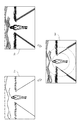
図1は、実施形態における飛行体システム10の第1構成例を示す模式図である。飛行体システム10は、無人航空機100及び端末80を備える。無人航空機100及び端末80は、相互に有線通信又は無線通信(例えば無線LAN(Local Area Network))により通信可能である。図1では、端末80が携帯端末(例えばスマートフォン、タブレット端末)であることを例示している。
FIG. 1 is a schematic diagram illustrating a first configuration example of an
なお、飛行体システムは、無人航空機、送信機(プロポ)、及び携帯端末を備えた構成であってよい。送信機を備える場合、送信機の前面に配置された左右の制御棒を使って、ユーザは、無人航空機の飛行の制御を指示可能である。また、この場合、無人航空機、送信機、及び携帯端末は、相互に有線通信又は無線通信により通信可能である。 The flying object system may have a configuration including an unmanned aerial vehicle, a transmitter (propo), and a portable terminal. When the transmitter is provided, the user can instruct the control of the flight of the unmanned aircraft using the left and right control rods arranged on the front surface of the transmitter. In this case, the unmanned aircraft, the transmitter, and the portable terminal can communicate with each other by wired communication or wireless communication.
図2は、実施形態における飛行体システム10の第2構成例を示す模式図である。図2では、端末80がPCであることを例示している。図1及び図2のいずれであっても、端末80が有する機能は同じでよい。
FIG. 2 is a schematic diagram illustrating a second configuration example of the
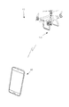
図3は、無人航空機100の具体的な外観の一例を示す図である。図3には、無人航空機100が移動方向STV0に飛行する場合の斜視図が示される。無人航空機100は移動体の一例である。
FIG. 3 is a diagram illustrating an example of a specific appearance of the unmanned
図3に示すように、地面と平行であって移動方向STV0に沿う方向にロール軸(x軸参照)が設定される。この場合、地面と平行であってロール軸に垂直な方向にピッチ軸(y軸参照)が設定され、更に、地面に垂直であってロール軸及びピッチ軸に垂直な方向にヨー軸(z軸参照)が設定される。 As shown in FIG. 3, a roll axis (see x-axis) is set in a direction parallel to the ground and along the movement direction STV0. In this case, a pitch axis (see the y-axis) is set in a direction parallel to the ground and perpendicular to the roll axis, and further, a yaw axis (z-axis) is perpendicular to the ground and perpendicular to the roll axis and the pitch axis. Reference) is set.
無人航空機100は、UAV本体102と、ジンバル200と、撮像部220と、複数の撮像部230とを含む構成である。
The unmanned
UAV本体102は、複数の回転翼(プロペラ)を備える。UAV本体102は、複数の回転翼の回転を制御することにより無人航空機100を飛行させる。UAV本体102は、例えば4つの回転翼を用いて無人航空機100を飛行させる。回転翼の数は、4つに限定されない。また、無人航空機100は、回転翼を有さない固定翼機でもよい。
The UAV
撮像部220は、所望の撮像範囲に含まれる被写体(例えば、空撮対象となる上空の様子、山や川等の景色、地上の建物)を撮像する撮像用のカメラでよい。
The
複数の撮像部230は、無人航空機100の飛行を制御するために無人航空機100の周囲を撮像するセンシング用のカメラでよい。2つの撮像部230が、無人航空機100の機首である正面に設けられてよい。さらに、他の2つの撮像部230が、無人航空機100の底面に設けられてよい。正面側の2つの撮像部230はペアとなり、いわゆるステレオカメラとして機能してよい。底面側の2つの撮像部230もペアとなり、ステレオカメラとして機能してよい。複数の撮像部230により撮像された画像に基づいて、無人航空機100の周囲の3次元空間データ(3次元形状データ)が生成されてよい。なお、無人航空機100が備える撮像部230の数は4つに限定されない。無人航空機100は、少なくとも1つの撮像部230を備えていればよい。無人航空機100は、無人航空機100の機首、機尾、側面、底面、及び天井面のそれぞれに少なくとも1つの撮像部230を備えてよい。撮像部230で設定できる画角は、撮像部220で設定できる画角より広くてよい。撮像部230は、単焦点レンズ又は魚眼レンズを有してよい。
The plurality of
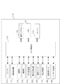
図4は、無人航空機100のハードウェア構成の一例を示すブロック図である。無人航空機100は、UAV制御部110と、通信インタフェース150と、メモリ160と、ストレージ170と、ジンバル200と、回転翼機構210と、撮像部220と、撮像部230と、GPS受信機240と、慣性計測装置(IMU:Inertial Measurement Unit)250と、磁気コンパス260と、気圧高度計270と、超音波センサ280と、レーザー測定器290と、を含む構成である。
FIG. 4 is a block diagram illustrating an example of a hardware configuration of the unmanned
UAV制御部110は、例えばCPU(Central Processing Unit)、MPU(Micro Processing Unit)又はDSP(Digital Signal Processor)を用いて構成される。UAV制御部110は、無人航空機100の各部の動作を統括して制御するための信号処理、他の各部との間のデータの入出力処理、データの演算処理及びデータの記憶処理を行う。UAV制御部110は、処理部の一例である。
The
UAV制御部110は、メモリ160に格納されたプログラムに従って無人航空機100の飛行を制御する。UAV制御部110は、飛行を制御してよい。UAV制御部110は、画像を空撮してよい。
The
UAV制御部110は、無人航空機100の位置を示す位置情報を取得する。UAV制御部110は、GPS受信機240から、無人航空機100が存在する緯度、経度及び高度を示す位置情報を取得してよい。UAV制御部110は、GPS受信機240から無人航空機100が存在する緯度及び経度を示す緯度経度情報、並びに気圧高度計270から無人航空機100が存在する高度を示す高度情報をそれぞれ位置情報として取得してよい。UAV制御部110は、超音波センサ280による超音波の放射点と超音波の反射点との距離を高度情報として取得してよい。
The
UAV制御部110は、磁気コンパス260から無人航空機100の向きを示す向き情報を取得してよい。向き情報は、例えば無人航空機100の機首の向きに対応する方位で示されてよい。
The
UAV制御部110は、撮像部220が撮像すべき撮像範囲を撮像する時に無人航空機100が存在すべき位置を示す位置情報を取得してよい。UAV制御部110は、無人航空機100が存在すべき位置を示す位置情報をメモリ160から取得してよい。UAV制御部110は、無人航空機100が存在すべき位置を示す位置情報を、通信インタフェース150を介して他の装置から取得してよい。UAV制御部110は、3次元地図データベースを参照して、無人航空機100が存在可能な位置を特定して、その位置を無人航空機100が存在すべき位置を示す位置情報として取得してよい。
The
UAV制御部110は、撮像部220及び撮像部230のそれぞれの撮像範囲を示す撮像範囲情報を取得してよい。UAV制御部110は、撮像範囲を特定するためのパラメータとして、撮像部220及び撮像部230の画角を示す画角情報を撮像部220及び撮像部230から取得してよい。UAV制御部110は、撮像範囲を特定するためのパラメータとして、撮像部220及び撮像部230の撮像方向を示す情報を取得してよい。UAV制御部110は、例えば撮像部220の撮像方向を示す情報として、ジンバル200から撮像部220の姿勢の状態を示す姿勢情報を取得してよい。撮像部220の姿勢情報は、ジンバル200のピッチ軸及びヨー軸の基準回転角度からの回転角度を示してよい。
The
UAV制御部110は、撮像範囲を特定するためのパラメータとして、無人航空機100が存在する位置を示す位置情報を取得してよい。UAV制御部110は、撮像部220及び撮像部230の画角及び撮像方向、並びに無人航空機100が存在する位置に基づいて、撮像部220が撮像する地理的な範囲を示す撮像範囲を画定し、撮像範囲情報を生成することで、撮像範囲情報を取得してよい。
The
UAV制御部110は、メモリ160から撮像範囲情報を取得してよい。UAV制御部110は、通信インタフェース150を介して撮像範囲情報を取得してよい。
The
UAV制御部110は、ジンバル200、回転翼機構210、撮像部220及び撮像部230を制御する。UAV制御部110は、撮像部220の撮像方向又は画角を変更することによって、撮像部220の撮像範囲を制御してよい。UAV制御部110は、ジンバル200の回転機構を制御することで、ジンバル200に支持されている撮像部220の撮像範囲を制御してよい。
The
撮像範囲とは、撮像部220又は撮像部230により撮像される地理的な範囲をいう。撮像範囲は、緯度、経度、及び高度で定義される。撮像範囲は、緯度、経度、及び高度で定義される3次元空間データにおける範囲でよい。撮像範囲は、緯度及び経度で定義される2次元空間データにおける範囲でもよい。撮像範囲は、撮像部220又は撮像部230の画角及び撮像方向、並びに無人航空機100が存在する位置に基づいて特定されてよい。撮像部220及び撮像部230の撮像方向は、撮像部220及び撮像部230の撮像レンズが設けられた正面が向く方位と俯角とから定義されてよい。撮像部220の撮像方向は、無人航空機100の機首の方位と、ジンバル200に対する撮像部220の姿勢の状態とから特定される方向でよい。撮像部230の撮像方向は、無人航空機100の機首の方位と、撮像部230が設けられた位置とから特定される方向でよい。
The imaging range refers to a geographical range captured by the
UAV制御部110は、複数の撮像部230により撮像された複数の画像を解析することで、無人航空機100の周囲の環境を特定してよい。UAV制御部110は、無人航空機100の周囲の環境に基づいて、例えば障害物を回避して飛行を制御してよい。
The
UAV制御部110は、無人航空機100の周囲に存在するオブジェクトの立体形状(3次元形状)を示す立体情報(3次元情報)を取得してよい。オブジェクトは、例えば、建物、道路、車、木等の風景の一部でよい。立体情報は、例えば、3次元空間データである。UAV制御部110は、複数の撮像部230から得られたそれぞれの画像から、無人航空機100の周囲に存在するオブジェクトの立体形状を示す立体情報を生成することで、立体情報を取得してよい。UAV制御部110は、メモリ160又はストレージ170に格納された3次元地図データベースを参照することにより、無人航空機100の周囲に存在するオブジェクトの立体形状を示す立体情報を取得してよい。UAV制御部110は、ネットワーク上に存在するサーバが管理する3次元地図データベースを参照することで、無人航空機100の周囲に存在するオブジェクトの立体形状に関する立体情報を取得してよい。
The
UAV制御部110は、回転翼機構210を制御することで、無人航空機100の飛行を制御する。つまり、UAV制御部110は、回転翼機構210を制御することにより、無人航空機100の緯度、経度、及び高度を含む位置を制御する。UAV制御部110は、無人航空機100の飛行を制御することにより、撮像部220の撮像範囲を制御してよい。UAV制御部110は、撮像部220が備えるズームレンズを制御することで、撮像部220の画角を制御してよい。UAV制御部110は、撮像部220のデジタルズーム機能を利用して、デジタルズームにより、撮像部220の画角を制御してよい。
The
撮像部220が無人航空機100に固定され、撮像部220を動かせない場合、UAV制御部110は、特定の日時に特定の位置に無人航空機100を移動させることにより、所望の環境下で所望の撮像範囲を撮像部220に撮像させてよい。あるいは撮像部220がズーム機能を有さず、撮像部220の画角を変更できない場合でも、UAV制御部110は、特定された日時に、特定の位置に無人航空機100を移動させることで、所望の環境下で所望の撮像範囲を撮像部220に撮像させてよい。
When the
通信インタフェース150は、端末80と通信する。通信インタフェース150は、任意の無線通信方式により無線通信してよい。通信インタフェース150は、任意の有線通信方式により有線通信してよい。通信インタフェース150は、空撮画像や空撮画像に関する付加情報(メタデータ)を、端末80に送信してよい。
The
メモリ160は、UAV制御部110がジンバル200、回転翼機構210、撮像部220、撮像部230、GPS受信機240、慣性計測装置250、磁気コンパス260、気圧高度計270、超音波センサ280、及びレーザー測定器290を制御するのに必要なプログラム等を格納する。メモリ160は、コンピュータ読み取り可能な記録媒体でよく、SRAM(Static Random Access Memory)、DRAM(Dynamic Random Access Memory)、EPROM(Erasable Programmable Read Only Memory)、EEPROM(Electrically Erasable Programmable Read-Only Memory)、及びUSB(Universal Serial Bus)メモリ等のフラッシュメモリの少なくとも1つを含んでよい。メモリ160は、無人航空機100から取り外し可能であってよい。メモリ160は、作業用メモリとして動作してよい。
The
ストレージ170は、HDD(Hard Disk Drive)、SSD(Solid State Drive)、SDカード、USBメモリ、その他のストレージの少なくとも1つを含んでよい。ストレージ170は、各種情報、各種データを保持してよい。ストレージ170は、無人航空機100から取り外し可能であってよい。ストレージ170は、空撮画像を記録してよい。
The
ジンバル200は、ヨー軸、ピッチ軸、及びロール軸を中心に撮像部220を回転可能に支持してよい。ジンバル200は、ヨー軸、ピッチ軸、及びロール軸の少なくとも1つを中心に撮像部220を回転させることで、撮像部220の撮像方向を変更してよい。
The
回転翼機構210は、複数の回転翼と、複数の回転翼を回転させる複数の駆動モータと、を有する。回転翼機構210は、UAV制御部110により回転を制御されることにより、無人航空機100を飛行させる。回転翼211の数は、例えば4つでもよいし、その他の数でもよい。また、無人航空機100は、回転翼を有さない固定翼機でもよい。
The
撮像部220は、所望の撮像範囲の被写体を撮像して撮像画像のデータを生成する。撮像部220の撮像により得られた画像データ(例えば空撮画像)は、撮像部220が有するメモリ、又はストレージ170に格納されてよい。
The
撮像部230は、無人航空機100の周囲を撮像して撮像画像のデータを生成する。撮像部230の画像データは、ストレージ170に格納されてよい。
The
GPS受信機240は、複数の航法衛星(つまり、GPS衛星)から発信された時刻及び各GPS衛星の位置(座標)を示す複数の信号を受信する。GPS受信機240は、受信された複数の信号に基づいて、GPS受信機240の位置(つまり、無人航空機100の位置)を算出する。GPS受信機240は、無人航空機100の位置情報をUAV制御部110に出力する。なお、GPS受信機240の位置情報の算出は、GPS受信機240の代わりにUAV制御部110により行われてよい。この場合、UAV制御部110には、GPS受信機240が受信した複数の信号に含まれる時刻及び各GPS衛星の位置を示す情報が入力される。
The
慣性計測装置250は、無人航空機100の姿勢を検出し、検出結果をUAV制御部110に出力する。慣性計測装置250は、無人航空機100の姿勢として、無人航空機100の前後、左右、及び上下の3軸方向の加速度と、ピッチ軸、ロール軸、及びヨー軸の3軸方向の角速度とを検出してよい。
磁気コンパス260は、無人航空機100の機首の方位を検出し、検出結果をUAV制御部110に出力する。
The
気圧高度計270は、無人航空機100が飛行する高度を検出し、検出結果をUAV制御部110に出力する。
超音波センサ280は、超音波を放射し、地面や物体により反射された超音波を検出し、検出結果をUAV制御部110に出力する。検出結果は、無人航空機100から地面までの距離つまり高度を示してよい。検出結果は、無人航空機100から物体(被写体)までの距離を示してよい。
The
レーザー測定器290は、物体にレーザー光を照射し、物体で反射された反射光を受光し、反射光により無人航空機100と物体(被写体)との間の距離を測定する。レーザー光による距離の測定方式は、一例として、タイムオブフライト方式でよい。
図5は、端末80のハードウェア構成の一例を示すブロック図である。端末80は、端末制御部81、操作部83、通信部85、メモリ87、表示部88、及びストレージ89を備える。端末80は、無人航空機100の飛行制御の指示を希望するユーザに所持され得る。
FIG. 5 is a block diagram illustrating an example of a hardware configuration of the terminal 80. The terminal 80 includes a
端末制御部81は、例えばCPU、MPU又はDSPを用いて構成される。端末制御部81は、端末80の各部の動作を統括して制御するための信号処理、他の各部との間のデータの入出力処理、データの演算処理及びデータの記憶処理を行う。
The
端末制御部81は、通信部85を介して、無人航空機100からのデータや情報を取得してよい。端末制御部81は、操作部83を介して入力されたデータや情報を取得してもよい。端末制御部81は、メモリ87に保持されたデータや情報を取得してもよい。端末制御部81は、通信部85を介して、無人航空機100へ、データや情報を送信してもよい。端末制御部81は、データや情報を表示部88に送り、このデータや情報に基づく表示情報を表示部88に表示させてもよい。
The
端末制御部81は、画像を合成して合成画像を生成するためのアプリケーションを実行してもよい。端末制御部81は、アプリケーションで用いられる各種のデータを生成してもよい。
The
操作部83は、端末80のユーザにより入力されるデータや情報を受け付けて取得する。操作部83は、ボタン、キー、タッチスクリーン、マイクロホン、等の入力装置を含んでもよい。ここでは、主に、操作部83と表示部88とがタッチパネルにより構成されることを例示する。この場合、操作部83は、タッチ操作、タップ操作、ドラック操作等を受付可能である。操作部83により入力された情報は、無人航空機100へ送信されてもよい。
The
通信部85は、各種の無線通信方式により、無人航空機100との間で無線通信する。この無線通信の無線通信方式は、例えば、無線LAN、Bluetooth(登録商標)、又は公衆無線回線を介した通信を含んでよい。通信部85は、任意の有線通信方式により有線通信してよい。
The
メモリ87は、例えば端末80の動作を規定するプログラムや設定値のデータが格納されたROMと、端末制御部81の処理時に使用される各種の情報やデータを一時的に保存するRAMを有してもよい。メモリ87は、ROM及びRAM以外のメモリが含まれてよい。メモリ87は、端末80の内部に設けられてよい。メモリ87は、端末80から取り外し可能に設けられてよい。プログラムは、アプリケーションプログラムを含んでよい。
The
表示部88は、例えばLCD(Liquid Crystal Display)を用いて構成され、端末制御部81から出力された各種の情報やデータを表示する。表示部88は、アプリケーションの実行に係る各種データや情報を表示してもよい。
The
ストレージ89は、各種データ、情報を蓄積し、保持する。ストレージ89は、HDD、SSD、SDカード、USBメモリ、等でよい。ストレージ89は、端末80の内部に設けられてもよい。ストレージ89は、端末80から取り外し可能に設けられてもよい。ストレージ89は、無人航空機100から取得された空撮画像や付加情報を保持してよい。付加情報は、メモリ87に保持されてよい。
The
なお、飛行体システム10が送信機(プロポ)を備える場合、端末80が実行する処理は、送信機が実行してもよい。送信機は、端末80と同様の構成部を有するので、詳細な説明については省略する。送信機は、制御部、操作部、通信部、表示部、メモリ、等を有する。飛行体システム10が送信機を有する場合、端末80が設けられなくてもよい。
When the flying
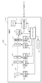
図6は、無人航空機100が備える撮像部220のハードウェア構成を示す図である。撮像部220は、筐体220zを有する。撮像部220は、筐体220zの内部に、カメラプロセッサ11、シャッタ12、撮像素子13、画像処理部14、メモリ15、シャッタ駆動部19、素子駆動部20、ゲイン制御部21、及びフラッシュ18を有する。なお、撮像部220における各構成の少なくとも一部は、設けられなくてもよい。
FIG. 6 is a diagram illustrating a hardware configuration of the
カメラプロセッサ11は、露光時間、絞り(アイリス)などの撮影条件を決定する。カメラプロセッサ11は、NDフィルタ32による減光分を加味して露光(AE:Automatic Exposure)制御を行ってよい。カメラプロセッサ11は、画像処理部14から出力された画像データから輝度レベル(例えば画素値)を算出してよい。カメラプロセッサ11は、算出した輝度レベルに基づいて撮像素子13に対するゲインの値を算出し、この算出結果をゲイン制御部21に送出してよい。カメラプロセッサ11は、算出した輝度レベルに基づいてシャッタ12を開閉するためのシャッタスピードの値を算出し、算出結果をシャッタ駆動部19に送出してよい。カメラプロセッサ11は、撮像素子13にタイミング信号を供給する素子駆動部20に、撮像の指示を送出してよい。
The
シャッタ12は、例えばフォーカルプレーンシャッタであり、シャッタ駆動部19により駆動される。シャッタ12の開放時に入射した光は、撮像素子13の撮像面上に結像する。撮像素子13は、撮像面上に結像した光学像を光電変換し、画像信号として出力する。撮像素子13には、CCD(Charge Coupled Device:電荷結合素子)イメージセンサやCMOS(Complementary Metal Oxide Semiconductor:相補型MOS)イメージセンサが用いられてよい。
The
ゲイン制御部21は、撮像素子13から入力された画像信号に対してノイズを低減し、撮像信号を増幅するゲイン(利得)を制御する。画像処理部14は、ゲイン制御部21によって増幅された撮像信号に対し、アナログデジタル変換を行って画像データを生成する。画像処理部14は、シェーディング補正、色補正、輪郭強調、ノイズ除去、ガンマ補正、ディベイヤ、圧縮等の各処理を行ってよい。
The
メモリ15は、各種データや画像データを記憶する記憶媒体である。メモリ15は、例えば、シャッタスピードS、F値、ISO感度、ND値を基に露光量を算出するための露光制御情報を保持してよい。ISO感度は、ゲインに対応する値である。ND値は減光フィルタによる減光度を表す。
The
シャッタ駆動部19は、カメラプロセッサ11から指示されたシャッタスピードでシャッタ12を開閉する。素子駆動部20は、タイミングジェネレータであり、カメラプロセッサ11からの撮像の指示に従い、撮像素子13にタイミング信号を供給し、撮像素子13の電荷の蓄積動作、読み出し動作、リセット動作等を行う。
The
フラッシュ18は、カメラプロセッサ11の指示に従い、夜間撮像時や逆光時に閃光し、被写体を照明する。フラッシュ18には、例えばLED(light Emitting Diode)ライトが用いられる。なお、フラッシュ18は省かれてもよい。
The
また、撮像部220は、筐体220zの内部に、NDフィルタ32、絞り33、レンズ群34、レンズ駆動部36、ND駆動部38、及び絞り駆動部40を有する。
The
レンズ群34は、被写体からの光を集光して撮像素子13に結像する。レンズ群34は、フォーカスレンズ、ズームレンズ、像振れ補正用レンズ、等を含む。レンズ群34は、レンズ駆動部36によって駆動される。レンズ駆動部36は、モータ(図示せず)を有し、カメラプロセッサ11からの制御信号を入力すると、ズームレンズ及びフォーカスレンズを含むレンズ群34を光軸opの方向(光軸方向)に移動させてよい。レンズ駆動部36は、ズームレンズを移動させてズーム倍率を変更するズーミング動作を行う場合、筐体220zの一部でありレンズ群34を収容する鏡筒を前後方向に伸縮させてよい。
The
絞り33は、絞り駆動部40によって駆動される。絞り駆動部40は、モータ(図示せず)を有し、カメラプロセッサ11からの制御信号を入力すると、絞り33の開口を拡縮する。
The diaphragm 33 is driven by the
NDフィルタ32は、光軸opの方向(光軸方向)において、例えば絞り33の近傍に配置され、入射する光の量を制限する減光を行う。ND駆動部38は、モータ(図示せず)を有し、カメラプロセッサ11からの制御信号を入力すると、NDフィルタ32を光軸op上に挿抜してよい。
The
次に、無人航空機100のUAV制御部110が有する画像生成に関する機能について説明する。UAV制御部110は、処理部の一例である。UAV制御部110は、撮像画像の合成に関する処理を行うことで、無人航空機100の飛行速度を超える速度で移動しているような効果(以下、高速飛行エフェクトとも称する)を施し、臨場感のある画像を生成可能である。UAV制御部110は、無人航空機100の停止中(例えばホバリング)に撮像される撮像画像を基に、高速飛行エフェクトを施してよい。
Next, functions related to image generation that the
UAV制御部110は、無人航空機100の動作モード(例えば飛行モード、撮像モード)を設定する。撮像モードは、撮像部220で撮像された撮像画像に高速飛行エフェクトを施すためのハイパースピード(Hyper Speed)撮像モードを含む。無人航空機100の動作モード(例えばハイパースピード撮像モード)は、例えば時間帯や無人航空機100の所在位置に基づいて無人航空機100自身のUAV制御部110により指示されてもよいし、通信インタフェース150を介して、端末80により遠隔で指示されてもよい。
The
UAV制御部110は、撮像部220で撮像された少なくとも1つの撮像画像を取得する。UAV制御部110は、撮像部220を介して、所定の露光量で、第1画像Gaを撮像して取得してよい。露光量は、例えば、シャッタスピード、絞り、ISO感度、ND値、等の少なくとも1つに基づいて決定されてよい。第1画像Gaが撮像される際の露光量は、任意であり、例えば0EVでよい。第1画像Gaが撮像される際の撮像部220のズーム倍率は、任意であり、例えば1.0でよい。第1画像Gaが撮像される際の撮像部220のシャッタスピードに対応する露光時間は、例えば1/30秒でよい。第1画像Gaは、1回の撮像の間に、ズーム倍率が変更されずに固定されて撮像される。第1画像Gaは、基本となる撮像であり、一般的な撮像であるので、通常画像とも称する。
The
UAV制御部110は、撮像部220を介して、所定の露光量で、第2画像Gbを撮像して取得してよい。第2画像Gbが撮像される際の露光量は、第1画像Gaが撮像される際の露光量と同じでよく、例えば1.0でよい。第1画像Gaと第2画像Gbとで露光量を同程度とすることで、第1画像Gaと第2画像Gbの明るさが変わらないように調整される。また、第2画像Gbが撮像される際のシャッタスピードは、第1画像Gaが撮像される際のシャッタスピード以下である。つまり、第2画像Gbが撮像される際の露光時間は、第1画像Gaが撮像される際の露光時間以上であり、例えば1秒である。なお、第1画像Gaと第2画像Gbとで露光量を不変であっても、第1画像Gaの撮像時の露光時間より第2画像Gbの撮像時の露光時間が長い場合、他のカメラパラメータ(例えば絞り、ISO感度、ND値)が適宜調整される。UAV制御部110は、カメラパラメータの情報を、例えば、メモリ160に保持させてよく、又は、撮像部220のカメラプロセッサ11を介してメモリ15に保持させてよい。
The
第2画像Gbは、1回の撮像の間に、ズーム倍率が変更される。ズーム倍率の変更範囲は任意であるが、第1画像Gaが撮像される際のズーム倍率以上となる変更範囲である。UAV制御部110は、第2画像Gbを撮像するための撮像部220のズーム倍率の変更範囲を決定する。UAV制御部110は、無人航空機100の飛行速度に基づいて、ズーム倍率の変更範囲を決定してよい。撮像部220のズーム倍率を大きくすると、撮像部220の画角が大きくなり、より被写体に接近した画像となる。第2画像Gbは、1回の撮像の間にズーム倍率が大きくなるよう変更されることで、被写体に接近するように進んでいるような画像となり、高速移動している感覚(高速感)を強調して演出できる。UAV制御部110は、ズーム倍率の情報やズーム倍率の変更範囲の情報を、例えば、メモリ160に保持させてよく、又は、撮像部220のカメラプロセッサ11を介してメモリ15に保持させてよい。
The zoom magnification of the second image Gb is changed during one imaging. The change range of the zoom magnification is arbitrary, but is a change range that is equal to or greater than the zoom magnification when the first image Ga is captured. The
第2画像Gbは、第1画像Gaが撮像される際よりも長時間にわたって露光されて撮像される場合、長時間露光画像とも称する。 The second image Gb is also referred to as a long-time exposure image when it is exposed and imaged for a longer time than when the first image Ga is imaged.
UAV制御部110は、無人航空機100の飛行速度を算出する。UAV制御部110は、慣性計測装置250により計測される加速度を積分演算することで、無人航空機100の飛行速度を算出して取得してよい。UAV制御部110は、GPS受信機240により計測される時間毎の現在位置を微分演算することで、無人航空機100の飛行速度を算出して取得してよい。
The
UAV制御部110は、第1画像Gaと第2画像Gbとを合成するためのブレンド率を決定する。UAV制御部110は、無人航空機100の飛行速度に基づいて、ブレンド率を決定してよい。UAV制御部110は、決定されたブレンド率に基づいて、第1画像Gaと第2画像Gbとを合成し、合成画像を生成する。第1画像Gaの画像範囲(画像サイズ)と第2画像Gbの画像範囲(画像サイズ)とは、同じ範囲(同じサイズ)でよい。よって合成画像の画像範囲(画像サイズ)も同じ範囲(同じサイズ)でよい。
The
合成画像では、合成画像の画素毎にブレンド率が異なってよい。合成画像では、合成画像における複数の画素が集合した領域毎に、ブレンド率が異なってよい。合成画像では、同一の領域内の各画素で、ブレンド率が同一でもよいし異なってもよい。 In the composite image, the blend ratio may be different for each pixel of the composite image. In the composite image, the blend rate may be different for each region where a plurality of pixels in the composite image are gathered. In the composite image, the blend ratio may be the same or different for each pixel in the same region.
なお、UAV制御部110は、3つ以上の画像を合成してよい。UAV制御部110は、3つ以上の画像を合成するための各画像のブレンド率を、上記と同様に決定してよい。
Note that the
図7は、無人航空機100の飛行速度に対応する、第2画像Gbが撮像される場合のズーム倍率の変更範囲を示すグラフである。このグラフは、光学ズーム及びデジタルズームの双方に適用可能であり、同時に適用されてもよい。このグラフに示すような無人航空機100の飛行速度に対応するズーム倍率の変更範囲の情報は、メモリ160に記憶されてよい。なお、ここでは、ズーム倍率の変更範囲の下端がズーム倍率1.0であることを想定するが、ズーム倍率の他の値を変更範囲の下端としてもよい。
FIG. 7 is a graph showing a zoom magnification change range when the second image Gb corresponding to the flight speed of the
図7では、飛行速度に対するズーム倍率の変更範囲の上端が直線で表されている。具体的には、飛行速度1km/hの場合、ズーム倍率の上端が値1.1である。この場合、ズーム倍率の変更範囲は、1.0〜1.1となる。飛行速度10km/hの場合、ズーム倍率の変更範囲の上端が値1.3である。この場合、ズーム倍率の変更範囲は、1.0〜1.3となる。飛行速度35km/hの場合、ズーム倍率の変更範囲の上端が値2.0(上端の最大値の一例)である。この場合、ズーム倍率の変更範囲は、1.0〜2.0となる。飛行速度50km/hの場合、ズーム倍率の変更範囲の上端は、同じく最大値2.0である。この場合、ズーム倍率の変更範囲は、1.0〜2.0となる。 In FIG. 7, the upper end of the change range of the zoom magnification with respect to the flight speed is represented by a straight line. Specifically, when the flight speed is 1 km / h, the upper end of the zoom magnification is 1.1. In this case, the change range of the zoom magnification is 1.0 to 1.1. When the flight speed is 10 km / h, the upper end of the zoom magnification changing range is 1.3. In this case, the zoom magnification change range is 1.0 to 1.3. When the flight speed is 35 km / h, the upper end of the zoom magnification change range is 2.0 (an example of the maximum value of the upper end). In this case, the zoom magnification change range is 1.0 to 2.0. When the flying speed is 50 km / h, the upper end of the zoom magnification changing range is also the maximum value 2.0. In this case, the zoom magnification change range is 1.0 to 2.0.
なお、図7では、ズーム倍率の変更範囲の上端の最大値が2.0であることを例示したが、他の値が変更範囲の上端の最大値であってもよい。また、図7では、飛行速度に対するズーム倍率の変更範囲の上端の変化は、直線で表されたが、S字カーブ等の曲線で表されてもよい。 In FIG. 7, the maximum value of the upper end of the zoom magnification change range is exemplified as 2.0, but another value may be the maximum value of the upper end of the change range. In FIG. 7, the change at the upper end of the zoom magnification change range with respect to the flight speed is represented by a straight line, but may be represented by a curve such as an S-shaped curve.
このように、ズーム倍率の変更範囲の上端は、無人航空機100の飛行速度が速くなる程、ズーム倍率が高くなるように設定される。つまり、無人航空機100の飛行速度が速くなる程、ズーム倍率の変更範囲が大きくなるよう設定される。これにより、第2画像Gbは、画像内の被写体の大きさがズーム倍率に応じて大きく変化するように描画される。これにより、飛行速度が速い程、高速感が高くなるような高速飛行エフェクトが実施され得る。
Thus, the upper end of the zoom magnification change range is set such that the zoom magnification increases as the flight speed of the unmanned
なお、ズーム倍率の最大値は、光学ズームやデジタルズームの最大倍率によって定まってよい。例えば、ズーム倍率の最大値は、撮像部220における光学ズームによるズーミング動作に要する時間(ズーミング時間)が、第2画像Gbが撮像される際の露光時間より長い場合、この露光時間の経過までに、ズーミング動作(鏡筒の移動)が到達できるズーム倍率によって制限され得る。よって、例えば、光学ズームするための機構動作が高速であれば、ズーム倍率の変更可能範囲が大きくなり、ズーム倍率の変更範囲が大きくてもズーミング動作が追従可能となってよい。 Note that the maximum value of the zoom magnification may be determined by the maximum magnification of the optical zoom or digital zoom. For example, the maximum value of the zoom magnification is the time required for zooming operation by the optical zoom in the imaging unit 220 (zooming time) longer than the exposure time when the second image Gb is imaged. The zooming operation (movement of the lens barrel) can be limited by the zoom magnification that can be reached. Therefore, for example, if the mechanism operation for optical zooming is fast, the zoom magnification changeable range becomes large, and the zooming operation may be able to follow even if the zoom magnification change range is large.
このように、UAV制御部110は、無人航空機100の飛行速度に基づいて、第2画像Gbを取得するためのズーム倍率の変更範囲を決定してよい。
As described above, the
これにより、無人航空機100は、無人航空機100の飛行速度に基づくズーム倍率の変更範囲が得られるので、無人航空機100は、どの程度の飛行速度を感じさせる画像とするかを決定できる。したがって、ユーザは、高速飛行エフェクトが施された画像を視認することで、無人航空機100がどの程度の飛行速度で飛行しているかを意識しながら、高速感を楽しめる。
Thereby, since the
また、無人航空機100の飛行速度が速い程、ズーム倍率の変更範囲が大きくなることで、第2画像Gb内の被写体への接近度合がより高く見える。よって、ユーザは、このズーム倍率の変化を、第1画像Gaと第2画像Gbとが合成された合成画像で感知でき、直感的に高速感を得やすくなる。
In addition, as the flying speed of the
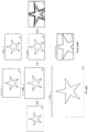
図8は、撮像部220で撮像された2枚の撮像画像としての第1画像Ga及び第2画像Gbを合成した合成画像Gmを示す図である。
FIG. 8 is a diagram illustrating a combined image Gm obtained by combining the first image Ga and the second image Gb as two captured images captured by the
合成画像Gmは、合成画像の中心(画像中心)から第1半径r1で囲まれる円形の画像領域gr1と、画像中心から第2半径r2で表される円形の内側と第1半径r1で表される円形の外側で囲まれるリング状の画像領域gr2と、画像領域gr2の外側の画像領域gr3と、を含む。例えば、画像中心から合成画像Gmの隅までの距離Lを値1.0とすると、第1半径r1は、値0.3であってよく、第2半径r2は、値0.7であってよい。なお、これらの値は一例であり、他の値(割合)で合成画像Gm中の領域が形成されてもよい。第1半径r1、第2半径r2の長さは、無人航空機100の飛行速度に応じて決定されてよい。
The composite image Gm is represented by a circular image region gr1 surrounded by a first radius r1 from the center (image center) of the composite image, a circular inside represented by a second radius r2 from the image center, and a first radius r1. A ring-shaped image region gr2 surrounded by a circular outer side and an image region gr3 outside the image region gr2. For example, if the distance L from the center of the image to the corner of the composite image Gm is 1.0, the first radius r1 may be 0.3 and the second radius r2 is 0.7. Good. Note that these values are examples, and regions in the composite image Gm may be formed with other values (ratio). The lengths of the first radius r1 and the second radius r2 may be determined according to the flight speed of the
合成画像Gmでは、第1画像Gaと第2画像Gbとが、決定されたブレンド率で合成されている。ブレンド率は、合成画像Gmの各画素における第2画像Gbの成分の割合で示されてよい。例えば、画像領域gr1には、第1画像Gaが、100%占め、第2画像Gbの成分が含まれない。つまり、画像領域gr1でのブレンド率は、値0.0である。画像領域gr3には、第2画像Gbが、100%占める。つまり、画像領域gr2でのブレンド率は、値1.0である。画像領域gr2には、第1画像Gaの成分と第2画像Gbの成分とを含み、ブレンド率が値0.0より大きく値1.0より小さくなる。 In the synthesized image Gm, the first image Ga and the second image Gb are synthesized at the determined blend rate. The blend ratio may be indicated by the ratio of the component of the second image Gb in each pixel of the composite image Gm. For example, the image region gr1 is 100% occupied by the first image Ga and does not include the component of the second image Gb. That is, the blend rate in the image region gr1 is 0.0. The second image Gb occupies 100% in the image region gr3. That is, the blend ratio in the image region gr2 is 1.0. The image region gr2 includes a component of the first image Ga and a component of the second image Gb, and the blend rate is greater than 0.0 and smaller than 1.0.
つまり、合成画像Gmにおいて、第2画像Gbの成分が多くなる程、ブレンド率が高くなり、全て第2画像Gbの成分になるとブレンド率が値1.0になる。一方、合成画像Gmにおいて、第2画像Gbの成分が少なくなる程、つまり第1画像Gaの成分が多くなる程、ブレンド率が低くなり、全て第1画像Gaの成分になるとブレンド率が値0.0になる。なお、画像領域gr1,gr2,gr3を同心円で区画されたが、三角、四角等の多角形やその他の形状で区画されてよい。 That is, in the composite image Gm, the blend rate increases as the component of the second image Gb increases, and the blend rate becomes 1.0 when all the components of the second image Gb become components. On the other hand, in the composite image Gm, the blend rate decreases as the component of the second image Gb decreases, that is, the component of the first image Ga increases. .0. Although the image regions gr1, gr2, and gr3 are partitioned by concentric circles, they may be partitioned by polygons such as triangles and squares and other shapes.
このように、合成画像Gmは、合成画像Gmの中心部(画像中心)から端部に向かって順に、第1画像Gaの成分を含み第2画像Gbの成分を含まない画像領域gr1(第1の領域の一例)と、第1画像Gaの成分と第2画像Gbの成分とを含む画像領域gr2(第2の領域の一例)と、第1画像Gaの成分を含まず第2画像Gbの成分を含む画像領域gr3(第3の領域の一例)と、を含んでよい。 Thus, the composite image Gm is an image region gr1 (first image) that includes the components of the first image Ga and does not include the components of the second image Gb in order from the center (image center) to the end of the composite image Gm. Of the first image Ga), the image region gr2 including the component of the first image Ga and the component of the second image Gb (an example of the second region), and the second image Gb not including the component of the first image Ga. And an image region gr3 (an example of a third region) including a component.
これにより、合成画像Gmの中心部に近い画像領域gr1に、固定のズーム倍率で撮像された第1画像Gaが描画されるので、被写体が鮮明に描画され、ユーザは被写体を認識し易い。また、合成画像Gmの端部に近い画像領域gr3に、ズーム倍率が変化しながらズームアップされた第2画像Gbが描画されるので、ユーザは高速感を得ることができる。また、画像領域gr1と画像領域gr3との間に、第1画像Gaの成分と第2画像Gbの成分とが含まれるので、無人航空機100は、画像領域gr1と画像領域gr3との間の遷移を滑らかにし、ユーザに違和感が低減された合成画像gmを提供できる。
As a result, the first image Ga captured at a fixed zoom magnification is drawn in the image region gr1 near the center of the composite image Gm, so that the subject is drawn clearly and the user can easily recognize the subject. Further, since the second image Gb zoomed up while the zoom magnification is changed is drawn in the image region gr3 near the end of the composite image Gm, the user can obtain a high speed feeling. In addition, since the component of the first image Ga and the component of the second image Gb are included between the image region gr1 and the image region gr3, the
図9は、合成画像Gmの画像中心からの距離に対応するブレンド率の変化を示すグラフである。このグラフで示されるブレンド率と半径との関係性の情報は、メモリ160に記憶されてよい。ここでは、5つのグラフg1,g2,g3,g4,g5が例示されている。
FIG. 9 is a graph showing a change in blend rate corresponding to the distance from the image center of the composite image Gm. Information on the relationship between the blend ratio and the radius shown in this graph may be stored in the
グラフg1,g2,g3,g4,g5は、無人航空機100の飛行速度の速さに対応して設定される。例えば、グラフg1は、飛行速度が50km/hである場合を示す。グラフg5は、飛行速度が10km/hである場合を示す。
The graphs g1, g2, g3, g4, and g5 are set corresponding to the speed of the
グラフg1〜g5では、合成画像Gmの画像中心から第1半径r1までの範囲(画像領域gr1に相当)では、ブレンド率が値0.0(0%)である。つまり、合成画像Gmにおいて、第1画像Gaが100%占める。グラフg1〜g5では、例えば第1半径r1が値0.15〜0.3に設定される。 In the graphs g1 to g5, the blend ratio is 0.0 (0%) in the range from the image center of the composite image Gm to the first radius r1 (corresponding to the image region gr1). That is, the first image Ga occupies 100% in the composite image Gm. In the graphs g1 to g5, for example, the first radius r1 is set to a value of 0.15 to 0.3.
グラフg1〜g5では、第1半径r1から第2半径r2までの範囲(画像領域gr2に相当)では、合成画像Gmの画像中心からの距離が長くなる程、ブレンド率が大きな値になるように設定される。例えば、グラフg1では、画像中心からの距離が値0.15から0.55に変化する間、ブレンド率は、値0.0〜値1.0に変化する。この区間における画像中心からの距離の変化に対するブレンド率の変化は、直線で表されてよい。直線の傾きは、任意に変更可能である。また、画像中心からの距離の変化に対するブレンド率の変化は、直線で表される他、S字カーブ等の曲線で表されてもよい。 In the graphs g1 to g5, in the range from the first radius r1 to the second radius r2 (corresponding to the image region gr2), the blend ratio increases as the distance from the image center of the composite image Gm increases. Is set. For example, in the graph g1, the blend ratio changes from the value 0.0 to the value 1.0 while the distance from the image center changes from the value 0.15 to 0.55. The change in the blend ratio with respect to the change in the distance from the image center in this section may be represented by a straight line. The slope of the straight line can be arbitrarily changed. Further, the change in the blend rate with respect to the change in the distance from the center of the image may be expressed by a curve such as an S-shaped curve in addition to a straight line.
グラフg1〜g5では、第2半径r2を超える範囲(撮像画像の中心からの距離が第2半径r2以上よりも大きい範囲であり、画像領域gr3に相当)では、ブレンド率は、値1.0(100%)に設定される。つまり、合成画像Gmにおいて、第2画像Gbが100%を占める。 In the graphs g1 to g5, in the range exceeding the second radius r2 (the distance from the center of the captured image is a range larger than the second radius r2 and corresponding to the image region gr3), the blend ratio is 1.0. (100%). That is, in the composite image Gm, the second image Gb occupies 100%.
このように、画像領域gr2では、画像領域gr1に近い端部ほど、第1画像Gaの比率が高い画像となり、画像領域gr3に近い端部ほど、第2画像Gbの比率が高い画像となってよい。例えば、図9では、グラフg1〜5のいずれにおいても、画像領域gr2に相当するブレンド率が変化している箇所では、右上がりのグラフとなっており、つまり合成画像Gmの画像中心からの距離が長い程、ブレンド率が高くなり、第2画像Gbの比率が高いことが理解できる。よって、画像領域gr2では、合成画像Gmの端部に近い程、第2画像Gbの成分が多くなってよい。 As described above, in the image area gr2, the edge closer to the image area gr1 is an image having a higher ratio of the first image Ga, and the edge closer to the image area gr3 is an image having a higher ratio of the second image Gb. Good. For example, in FIG. 9, in any of the graphs g1 to g5, the graph is a graph rising to the right at the portion where the blend ratio corresponding to the image region gr2 changes, that is, the distance from the center of the composite image Gm. It can be understood that the longer the is, the higher the blend ratio is and the higher the ratio of the second image Gb is. Therefore, in the image region gr2, the component of the second image Gb may increase as it is closer to the end of the composite image Gm.
これにより、画像領域gr2において合成画像Gmの中心側に向かう程、実空間上の被写体に近い画像となり、合成画像Gmの端部側に向かう程、高速感のある高速飛行エフェクトが強くなる。したがって、無人航空機100は、被写体を視認し易い状態を維持しつつ、高速感を得ることができる。また、無人航空機100は、画像領域gr1と画像領域gr3とを違和感なく滑らかに繋げることができる。
As a result, the closer to the center of the composite image Gm in the image region gr2, the closer to the subject in the real space, and the faster the high-speed flight effect with a higher speed becomes stronger toward the end of the composite image Gm. Accordingly, the unmanned
また、合成画像Gmでは、無人航空機100の飛行速度が速い程、画像領域gr1が小さく、画像領域gr3が大きくなってよい。例えば、より低速飛行に対応する図9のグラフg5では、画像中心からの距離が値0.75の位置からブレンド率1.0の画像領域gr3となっているのに対し、より高速飛行に対応する図9のグラフg1では、画像中心からの距離が値0.55の位置からブレンド率1.0の画像領域gr3となっている。
In the composite image Gm, the faster the flying speed of the
これにより、無人航空機100の飛行速度が速い場合には、鮮明な被写体が描画される第1画像Gaの面積が小さくなり、高速に移動する場合と同様の効果が得られる。また、高速感のある画像領域gr3が大きくなることで、より高速に飛行しているように演出可能である。
Thereby, when the flight speed of the unmanned
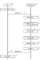
図10は、飛行体システム10の動作例を示すシーケンス図である。図10では、無人航空機100が飛行中である場合を想定する。
FIG. 10 is a sequence diagram illustrating an operation example of the flying
端末80では、端末制御部81は、操作部83を介して、ユーザからハイパースピード撮像モードとするための操作を受け付けると、ハイパースピード撮像モードを設定する(T1)。端末制御部81は、通信部85を介して、ハイパースピード撮像モードの設定を含む設定情報を無人航空機100に送信する(T2)。
In the terminal 80, when receiving an operation for setting the hyper speed imaging mode from the user via the
無人航空機100では、UAV制御部110は、通信インタフェース150を介して、端末80から設定情報を受信し、ハイパースピード撮像モードに設定し、設定情報をメモリ160に記憶する。UAV制御部110は、例えば、無人航空機100の飛行速度を算出して取得する(T3)。
In the
UAV制御部110は、メモリ160に記憶された、例えば図7に示したグラフの情報を基に、飛行速度に対応するズーム倍率を決定する(T4)。UAV制御部110は、メモリ160に記憶された、例えば図9に示すグラフを基に、飛行速度に対応する、合成画像における各領域や各画素でのブレンド率の変化を決定する(T5)。UAV制御部110は、決定されたズーム倍率及びブレンド率の変化を設定し、メモリ160及びメモリ15に記憶する。
The
UAV制御部110は、撮像部220による撮像を制御する。撮像部220のカメラプロセッサ11は、シャッタ駆動部19を制御し、被写体を含む第1画像Gaを撮像する(T6)。カメラプロセッサ11は、第1画像Gaをメモリ160に記憶させてよい。
The
カメラプロセッサ11は、メモリ15等に記憶されたズーム倍率の変更範囲の情報を基に、ズーミング動作を行いながら、シャッタ駆動部19を制御し、被写体を含む第2画像Gbを撮像する(T7)。カメラプロセッサ11は、第2画像Gbをメモリ160に記憶させてよい。
The
UAV制御部110は、メモリ160に記憶された第1画像Ga及び第2画像Gbを、T5で決定されたブレンド率に従って合成し、合成画像Gmを生成する(T8)。
The
なお、ここでは、撮像開始前の飛行速度でブレンド率の変化が決定されたが、これに限られない。例えば、UAV制御部110は、飛行速度の情報を、逐次取得してよい。例えば、UAV制御部110は、手順T6,T7で撮像する際の飛行速度の値を用いて、ブレンド率を決定してよいし、手順T6,T7で撮像する際の飛行速度の値の平均値に従って、ブレンド率を決定してもよい。
Here, although the change in the blend rate is determined at the flight speed before the start of imaging, the present invention is not limited to this. For example, the
UAV制御部110は、通信インタフェース150を介して、端末80に合成画像Gmを送信する(T9)。
The
端末80では、端末制御部81は、通信部85を介して、無人航空機100から合成画像Gmを受信すると、表示部88に合成画像Gmを表示させる(T10)。
In the terminal 80, when receiving the composite image Gm from the unmanned
なお、手順T8では、手順T6で撮像された第1画像Gaと、手順T7で撮像された第2画像Gbとの2枚の撮像画像を使って合成画像Gmを生成したが、1枚の撮像画像を基に、合成画像Gmを生成してよい。 In step T8, the composite image Gm is generated using the two captured images of the first image Ga captured in the procedure T6 and the second image Gb captured in the procedure T7. A composite image Gm may be generated based on the image.
図10の処理によれば、無人航空機100は、無人航空機100で撮像された際の実際の移動速度よりも、高速感が強調された画像を生成でき、人工的に高速感を演出できる。よって、例えば無人航空機100の飛行高度が高く、高速飛行感が出にくい場合でも、高速感を得やすい画像を生成できる。
According to the process of FIG. 10, the unmanned
なお、無人航空機100は、無人航空機100が飛行していない場合でも、無人航空機100が撮像された撮像画像に対して上記の高速移動エフェクトを施すことで、無人航空機100が高速移動しているような画像を疑似的に生成してよい。
The
図11は、第1画像Gaと第2画像Gbと合成画像Gmとの一例を示す図である。合成画像Gmは、高速飛行エフェクトが施された画像となる。 FIG. 11 is a diagram illustrating an example of the first image Ga, the second image Gb, and the composite image Gm. The composite image Gm is an image that has been subjected to the high-speed flight effect.
被写体は、一例として人物及び背景を含む。第1画像Gaは、無人航空機100の飛行速度に見合った速度で流れる比較的被写体が鮮明な画像である。第2画像Gbは、ズーミング動作されながら撮像された画像であり、高速に移動するような視覚効果を有する画像である。よって、第2画像Gbは、例えば、第2画像Gbの画像中心に位置する被写体の周囲に放射状の光の筋が入ったような画像となる。合成画像Gmは、第1画像Gaと第2画像Gbとが、飛行速度に応じたブレンド率で合成された画像である。よって、合成画像Gmは、画像中心にいる人物に急接近するように人物の周囲(背景)が流れたような画像となる。
The subject includes a person and a background as an example. The first image Ga is an image with a relatively clear subject that flows at a speed commensurate with the flight speed of the
具体的には、合成画像Gmは、画像中心付近は第1画像Gaと同一であり、画像端部付近は第2画像Gbと同一であり、画像中心付近と画像端部付近との間は第1画像Gaの成分と第2画像Gbの成分とが混在した画像となる。よって、合成画像Gmは、画像中心付近では鮮明な画像となるので、どのような被写体が描画されているか理解し易い。また、合成画像Gmは、画像端部付近ではズーム倍率が変化する画像つまり複数のズーム倍率の画像成分を含む画像となるので、合成画像Gmを見るユーザに対し、高速感や臨場感を演出できる。 Specifically, the composite image Gm is the same as the first image Ga in the vicinity of the image center, is the same as the second image Gb in the vicinity of the image edge, and the first image Ga between the image center and the vicinity of the image edge. The image is a mixed image of the component of the first image Ga and the component of the second image Gb. Therefore, since the composite image Gm is a clear image near the center of the image, it is easy to understand what kind of subject is drawn. Further, the composite image Gm is an image in which the zoom magnification changes near the edge of the image, that is, an image including a plurality of zoom magnification image components. .
このように、無人航空機100では、UAV制御部110は、無人航空機100の飛行速度(移動速度の一例)を取得する。撮像部220は、ズーム倍率を固定して第1画像Ga(第1の画像の一例)を撮像して取得する。撮像部220は、ズーム倍率を変化させながら第1画像Ga(第1画像Gaに写り込んだ被写体)が拡大された第2画像Gb(第2の画像の一例)を取得する。UAV制御部110は、無人航空機100の飛行速度に基づいて、第1画像Gaと第2画像Gbとを合成するためのブレンド率(合成比率の一例)を決定する。UAV制御部110は、決定されたブレンド率に基づいて、第1画像Gaと第2画像Gbとを合成し、合成画像Gmを生成する。
Thus, in unmanned
これにより、無人航空機100は、無人航空機100で撮像される画像を用いて、高速移動エフェクトが施された画像を容易に得ることができる。よって、ユーザは、例えばPC等を手動で操作しながらエフェクトをかける必要がなく、高速移動エフェクトが施された画像を得るために、例えば移動前や移動後の被写体の位置等を細かく調整しながら画像を編集しないで済む。したがって、無人航空機100は、ユーザの操作の煩雑性を低減でき、誤操作も低減できる。
Thereby, the unmanned
また、UAV制御部110は、撮像部220のズーム倍率を変更しながら、第2画像Gbを撮像して取得してよい。
In addition, the
これにより、無人航空機100は、第2画像Gbとして実空間の画像を撮像するので、例えば、第2画像Gbを演算により生成する場合と比較すると、第2画像Gbを取得するための無人航空機100の処理負荷を低減できる。
Thereby, since the
また、UAV制御部110は、撮像部220を介して、第1画像Gaを撮像するための露光時間t1(第1の露光時間の一例)よりも第2画像Gbを撮像するための露光時間t2(第2の露光時間の一例)を長くして、第2画像Gbを撮像してよい。つまり、第2画像Gbが長時間露光画像であってよい。
Further, the
これにより、無人航空機100は、高速移動エフェクトに主に寄与する第2画像Gbの露光時間を長くすることで、第2画像Gbの撮像中にズーム倍率を変更するための時間を確保できる。よって、無人航空機100は、例えばズーミング動作において光学ズームを用いる場合でも、ユーザが所望するズーム倍率に変更しながら、第2画像Gbを撮像し易くなる。
Thereby, the unmanned
次に、1枚の撮像画像に基づく合成画像Gmの生成について説明する。 Next, generation of the composite image Gm based on one captured image will be described.
図10では、撮像画像として複数枚の画像(第1画像Ga,第2画像Gb)が撮像されることを示したが、1枚の撮像画像(第1画像Ga)を基に、合成画像Gmが生成されてもよい。この場合、UAV制御部110は、第1画像Gaに対し、異なるズーム倍率で拡大された複数の拡大画像を生成してよい。UAV制御部110は、生成されたこれらの複数の拡大画像を所定のサイズに切り出して複数の切り出し画像を生成し、複数の切り出し画像を合成して、第2画像Gbを生成してよい。この第2画像Gbは、例えば複数の切り出し画像の各画素値を平均化することで生成されてよい。そして、UAV制御部110は、撮像により得られた第1画像Gaと演算により得られた第2画像Gbとを合成し、合成画像Gmを生成してよい。
FIG. 10 illustrates that a plurality of images (first image Ga, second image Gb) are captured as captured images. However, based on one captured image (first image Ga), a composite image Gm is illustrated. May be generated. In this case, the
図12は、1枚の撮像画像を基に合成画像Gmを生成することを説明するための図である。 FIG. 12 is a diagram for describing generation of a composite image Gm based on one captured image.
図12では、UAV制御部110は、1枚の第1画像Gaを基に、10枚の拡大画像B1〜B10を生成している。具体的には、UAV制御部110は、ズーム倍率を1.1として撮像画像Aが1.1倍に拡大された拡大画像B1、ズーム倍率を1.2として撮像画像Aが1.2倍に拡大された拡大画像B2、・・・、ズーム倍率を2.0として撮像画像Aが2.0倍に拡大された拡大画像B10、を生成してよい。
In FIG. 12, the
なお、各ズーム倍率は一例であり、各ズーム倍率を他の値に変更してもよい。また、ズーム倍率を一定の差分で変更せずに、様々な差分値でズーム倍率を変更してもよい。 Note that each zoom magnification is an example, and each zoom magnification may be changed to another value. Further, the zoom magnification may be changed with various difference values without changing the zoom magnification with a constant difference.
UAV制御部110は、拡大画像B1〜B10の各々から、主被写体を含むように、撮像画像Aと同じサイズの範囲を切り出し、切り出し画像B1’〜B10’を生成する。UAV制御部110は、切り出し画像B1’〜B10’を合成し、1枚の第2画像Gbを生成する。この場合、UAV制御部110は、切り出し画像B1’〜B10’のそれぞれ対応する画素値を加算して平均し、第2画像Gbを生成してよい。よって、演算により得られた第2画像Gbは、1回の撮像でズーム倍率を変更しながら主被写体に接近するように撮像された画像と同様に、高速感が得られる画像となる。
The
なお、図12の例では、図7に示した無人航空機100の飛行速度が35km/hや50km/hの場合を想定している。そのため、図12で得られた第2画像Gbは、ズーム倍率を1.0から2.0に変更しながら撮像して得られる第2画像と同様の効果が得られる。
In the example of FIG. 12, it is assumed that the flight speed of the
このように、UAV制御部110は、複数の異なるズーム倍率で第1画像Gaが拡大(ズームアップ)されて切り出された複数の切り出し画像B1’〜B10’(第3の画像の一例)を生成し、複数の切り出し画像B1’〜B10’を合成して第2画像Gbを生成してよい。
As described above, the
これにより、撮像部220による撮像が1回で済むので、撮像部220の撮像負担を軽減できる。つまり、撮像部220が第2画像Gbを撮像する代わりに、第1画像Gaを基に画像を加工して第2画像Gbを生成してよい。また、第1画像Gaを1回撮像した後には無人航空機100が移動しなくてもよく、例えば無人航空機100が停止した状態でも、高速感のある画像を合成画像Gmとして生成できる。
Thereby, since the imaging by the
以上、本開示を実施形態を用いて説明したが、本開示の技術的範囲は上述した実施形態に記載の範囲には限定されない。上述した実施形態に、多様な変更又は改良を加えることが当業者に明らかである。その様な変更又は改良を加えた形態も本開示の技術的範囲に含まれ得ることが、特許請求の範囲の記載からも明らかである。 As mentioned above, although this indication was explained using an embodiment, the technical scope of this indication is not limited to the range as described in an embodiment mentioned above. It will be apparent to those skilled in the art that various modifications and improvements can be made to the embodiment described above. It is also apparent from the scope of the claims that the embodiments added with such changes or improvements can be included in the technical scope of the present disclosure.
特許請求の範囲、明細書、及び図面中において示した装置、システム、プログラム、及び方法における動作、手順、ステップ、及び段階等の各処理の実行順序は、特段「より前に」、「先立って」等と明示しておらず、前の処理の出力を後の処理で用いるのでない限り、任意の順序で実現可能である。特許請求の範囲、明細書、及び図面中の動作フローに関して、便宜上「先ず、」、「次に」等を用いて説明したとしても、この順で実施することが必須であることを意味するものではない。 The execution order of each process such as operation, procedure, step, and stage in the apparatus, system, program, and method shown in the claims, the description, and the drawings is particularly “before” or “prior to”. ”And the like, and can be realized in any order unless the output of the previous process is used in the subsequent process. Regarding the operation flow in the claims, the description, and the drawings, even if it is described using “first,” “next,” etc. for convenience, it means that it is essential to carry out in this order. is not.
上記実施形態では、移動体として、無人航空機を示したが、本開示は、これに限らず、カメラを搭載した無人自動車、カメラを搭載した自転車、人が移動しながら把持するカメラ付きのジンバル装置等に適用することも可能である。 In the above embodiment, an unmanned aerial vehicle is shown as a moving body. However, the present disclosure is not limited to this, and an unmanned automobile equipped with a camera, a bicycle equipped with a camera, and a gimbal device with a camera that a person grips while moving. It is also possible to apply to the above.
10 飛行体システム
11 カメラプロセッサ
12 シャッタ
13 撮像素子
14 画像処理部
15 メモリ
18 フラッシュ
19 シャッタ駆動部
20 素子駆動部
21 ゲイン制御部
32 NDフィルタ
33 絞り
34 レンズ群
36 レンズ駆動部
38 ND駆動部
40 絞り駆動部
80 端末
81 端末制御部
83 操作部
85 通信部
87 メモリ
88 表示部
89 ストレージ
100 無人航空機
110 UAV制御部
150 通信インタフェース
160 メモリ
170 ストレージ
200 ジンバル
210 回転翼機構
220,230 撮像部
220z 筐体
240 GPS受信機
250 慣性計測装置
260 磁気コンパス
270 気圧高度計
280 超音波センサ
290 レーザー測定器
op 光軸
DESCRIPTION OF
Claims (20)
前記処理部は、
前記移動体の移動速度を取得し、
前記撮像部を介して、前記撮像部のズーム倍率を固定して第1の画像を撮像し、
ズーム倍率が変化しながら前記第1の画像がズームアップされた第2の画像を取得し、
前記移動体の移動速度に基づいて、前記第1の画像と前記第2の画像とを合成するための合成比率を決定し、
決定された前記合成比率に基づいて、前記第1の画像と前記第2の画像とを合成して、合成画像を生成する、
移動体。 A moving body including an imaging unit and a processing unit,
The processor is
Obtaining the moving speed of the moving object;
The first image is captured with the zoom magnification of the imaging unit fixed through the imaging unit,
Obtaining a second image in which the first image is zoomed up while the zoom magnification is changed;
Determining a combining ratio for combining the first image and the second image based on a moving speed of the moving body;
Based on the determined combination ratio, the first image and the second image are combined to generate a combined image;
Moving body.
請求項1に記載の移動体。 The processing unit captures the second image through the imaging unit while changing the zoom magnification of the imaging unit.
The moving body according to claim 1.
請求項2に記載の移動体。 The processing unit makes the second exposure time for capturing the second image longer than the first exposure time for capturing the first image via the imaging unit, and Taking a second image,
The moving body according to claim 2.
前記第1の画像が複数の異なるズーム倍率でズームアップされた複数の第3の画像を生成し、
複数の前記第3の画像を合成(例えば各画像の画素値を平均化)して、前記第2の画像を生成する、
請求項1に記載の移動体。 The processor is
Generating a plurality of third images in which the first image is zoomed up at a plurality of different zoom magnifications;
Combining the plurality of third images (for example, averaging pixel values of each image) to generate the second image;
The moving body according to claim 1.
請求項1〜4のいずれか1項に記載の移動体。 The processing unit determines a zoom magnification change range for acquiring the second image based on a moving speed of the moving body.
The moving body according to any one of claims 1 to 4.
請求項5に記載の移動体。 The faster the moving speed of the moving body is, the larger the change range of the zoom magnification is.
The moving body according to claim 5.
請求項1〜6のいずれか1項に記載の移動体。 The composite image includes, in order from the center to the end of the composite image, a first region that includes the component of the first image and does not include the component of the second image, and the first image A second region that includes a component and a component of the second image, and a third region that does not include the component of the first image and includes the component of the second image,
The moving body according to any one of claims 1 to 6.
請求項7に記載の移動体。 In the second region, the closer the position in the second region is to the end of the composite image, the more components of the second image,
The moving body according to claim 7.
請求項7または8に記載の移動体。 In the composite image, the faster the moving speed of the moving body, the smaller the first area and the larger the third area.
The moving body according to claim 7 or 8.
前記移動体の移動速度を取得するステップと、
前記移動体が備える撮像部のズーム倍率を固定して第1の画像を撮像するステップと、
ズーム倍率が変化しながら前記第1の画像がズームアップされた第2の画像を取得するステップと、
前記移動体の移動速度に基づいて、前記第1の画像と前記第2の画像とを合成するための合成比率を決定するステップと、
決定された前記合成比率に基づいて、前記第1の画像と前記第2の画像とを合成して、合成画像を生成するステップと、
を有する画像生成方法。 An image generation method in a moving object,
Obtaining a moving speed of the moving body;
Capturing a first image while fixing a zoom magnification of an imaging unit included in the moving body;
Obtaining a second image in which the first image is zoomed up while changing a zoom magnification;
Determining a combining ratio for combining the first image and the second image based on the moving speed of the moving body;
Combining the first image and the second image based on the determined composition ratio to generate a composite image;
An image generation method comprising:
請求項10に記載の画像生成方法。 Acquiring the second image includes capturing the second image while changing a zoom magnification of the imaging unit;
The image generation method according to claim 10.
請求項11に記載の画像生成方法。 The step of acquiring the second image includes setting a second exposure time for capturing the second image longer than a first exposure time for capturing the first image, and Capturing two images,
The image generation method according to claim 11.
前記第1の画像が複数の異なるズーム倍率でズームアップされた複数の第3の画像を生成するステップと、
複数の前記第3の画像を合成して、前記第2の画像を生成するステップと、を含む、
請求項10に記載の画像生成方法。 Acquiring the second image comprises:
Generating a plurality of third images in which the first image is zoomed up at a plurality of different zoom magnifications;
Combining the plurality of third images to generate the second image,
The image generation method according to claim 10.
請求項10〜13のいずれか1項に記載の画像生成方法。 The step of acquiring the second image includes a step of determining a change range of the zoom magnification for acquiring the second image based on a moving speed of the moving body.
The image generation method of any one of Claims 10-13.
請求項14に記載の画像生成方法。 The faster the moving speed of the moving body is, the larger the change range of the zoom magnification is.
The image generation method according to claim 14.
請求項10〜15のいずれか1項に記載の画像生成方法。 The composite image includes, in order from the center to the end of the composite image, a first region that includes the component of the first image and does not include the component of the second image, and the first image A second region that includes a component and a component of the second image, and a third region that does not include the component of the first image and includes the component of the second image,
The image generation method of any one of Claims 10-15.
請求項16に記載の画像生成方法。 In the second region, the closer the position in the second region is to the end of the composite image, the more components of the second image,
The image generation method according to claim 16.
請求項16または17に記載の画像生成方法。 In the composite image, the faster the moving speed of the moving body, the smaller the first area and the larger the third area.
The image generation method according to claim 16 or 17.
前記移動体の移動速度を取得するステップと、
前記移動体が備える撮像部のズーム倍率を固定して第1の画像を撮像するステップと、
ズーム倍率が変化しながら前記第1の画像がズームアップされた第2の画像を取得するステップと、
前記移動体の移動速度に基づいて、前記第1の画像と前記第2の画像とを合成するための合成比率を決定するステップと、
決定された前記合成比率に基づいて、前記第1の画像と前記第2の画像とを合成して、合成画像を生成するステップと、
を実行させるための、プログラム。 On the moving body,
Obtaining a moving speed of the moving body;
Capturing a first image while fixing a zoom magnification of an imaging unit included in the moving body;
Obtaining a second image in which the first image is zoomed up while changing a zoom magnification;
Determining a combining ratio for combining the first image and the second image based on the moving speed of the moving body;
Combining the first image and the second image based on the determined composition ratio to generate a composite image;
A program for running
前記移動体の移動速度を取得するステップと、
前記移動体が備える撮像部のズーム倍率を固定して第1の画像を撮像するステップと、
ズーム倍率が変化しながら前記第1の画像がズームアップされた第2の画像を取得するステップと、
前記移動体の移動速度に基づいて、前記第1の画像と前記第2の画像とを合成するための合成比率を決定するステップと、
決定された前記合成比率に基づいて、前記第1の画像と前記第2の画像とを合成して、合成画像を生成するステップと、
を実行させるためのプログラムを記録したコンピュータ読取り可能な記録媒体。 On the moving body,
Obtaining a moving speed of the moving body;
Capturing a first image while fixing a zoom magnification of an imaging unit included in the moving body;
Obtaining a second image in which the first image is zoomed up while changing a zoom magnification;
Determining a combining ratio for combining the first image and the second image based on the moving speed of the moving body;
Combining the first image and the second image based on the determined composition ratio to generate a composite image;
The computer-readable recording medium which recorded the program for performing this.
Priority Applications (4)
| Application Number | Priority Date | Filing Date | Title |
|---|---|---|---|
| JP2018103758A JP2019207635A (en) | 2018-05-30 | 2018-05-30 | Mobile body, image generating method, program, and recording medium |
| CN201980003198.XA CN110800287B (en) | 2018-05-30 | 2019-05-28 | Moving object, image generation method, program, and recording medium |
| PCT/CN2019/088775 WO2019228337A1 (en) | 2018-05-30 | 2019-05-28 | Moving object, image generation method, program, and recording medium |
| US16/950,461 US20210092306A1 (en) | 2018-05-30 | 2020-11-17 | Movable body, image generation method, program, and recording medium |
Applications Claiming Priority (1)
| Application Number | Priority Date | Filing Date | Title |
|---|---|---|---|
| JP2018103758A JP2019207635A (en) | 2018-05-30 | 2018-05-30 | Mobile body, image generating method, program, and recording medium |
Publications (1)
| Publication Number | Publication Date |
|---|---|
| JP2019207635A true JP2019207635A (en) | 2019-12-05 |
Family
ID=68697156
Family Applications (1)
| Application Number | Title | Priority Date | Filing Date |
|---|---|---|---|
| JP2018103758A Ceased JP2019207635A (en) | 2018-05-30 | 2018-05-30 | Mobile body, image generating method, program, and recording medium |
Country Status (4)
| Country | Link |
|---|---|
| US (1) | US20210092306A1 (en) |
| JP (1) | JP2019207635A (en) |
| CN (1) | CN110800287B (en) |
| WO (1) | WO2019228337A1 (en) |
Families Citing this family (1)
| Publication number | Priority date | Publication date | Assignee | Title |
|---|---|---|---|---|
| US11869236B1 (en) * | 2020-08-24 | 2024-01-09 | Amazon Technologies, Inc. | Generating data for training vision-based algorithms to detect airborne objects |
Citations (2)
| Publication number | Priority date | Publication date | Assignee | Title |
|---|---|---|---|---|
| JP2011035777A (en) * | 2009-08-04 | 2011-02-17 | Aisin Seiki Co Ltd | Support system for perception of vehicle surroundings |
| JP2015170989A (en) * | 2014-03-07 | 2015-09-28 | 西日本高速道路エンジニアリング関西株式会社 | Apparatus for capturing image of tunnel wall surface |
Family Cites Families (11)
| Publication number | Priority date | Publication date | Assignee | Title |
|---|---|---|---|---|
| JPH10178539A (en) * | 1996-12-17 | 1998-06-30 | Fuji Xerox Co Ltd | Image processing unit and image processing method |
| JPH10233919A (en) * | 1997-02-21 | 1998-09-02 | Fuji Photo Film Co Ltd | Image processor |
| JP3695119B2 (en) * | 1998-03-05 | 2005-09-14 | 株式会社日立製作所 | Image synthesizing apparatus and recording medium storing program for realizing image synthesizing method |
| US6888577B2 (en) * | 2000-01-24 | 2005-05-03 | Matsushita Electric Industrial Co., Ltd. | Image compositing device, recording medium, and program |
| JP4596219B2 (en) * | 2001-06-25 | 2010-12-08 | ソニー株式会社 | Image processing apparatus and method, recording medium, and program |
| JP4596224B2 (en) * | 2001-06-27 | 2010-12-08 | ソニー株式会社 | Image processing apparatus and method, recording medium, and program |
| JP4321287B2 (en) * | 2004-02-10 | 2009-08-26 | ソニー株式会社 | Imaging apparatus, imaging method, and program |
| KR100657522B1 (en) * | 2006-03-31 | 2006-12-15 | 삼성전자주식회사 | Apparatus and method for out-focusing photographing of portable terminal |
| US8687918B2 (en) * | 2008-03-05 | 2014-04-01 | Semiconductor Energy Laboratory Co., Ltd. | Image processing method, image processing system, and computer program |
| JP2010268441A (en) * | 2009-04-16 | 2010-11-25 | Sanyo Electric Co Ltd | Image processor, imaging device, and image reproducing device |
| CN106603931A (en) * | 2017-02-27 | 2017-04-26 | 努比亚技术有限公司 | Binocular shooting method and device |
-
2018
- 2018-05-30 JP JP2018103758A patent/JP2019207635A/en not_active Ceased
-
2019
- 2019-05-28 WO PCT/CN2019/088775 patent/WO2019228337A1/en active Application Filing
- 2019-05-28 CN CN201980003198.XA patent/CN110800287B/en active Active
-
2020
- 2020-11-17 US US16/950,461 patent/US20210092306A1/en not_active Abandoned
Patent Citations (2)
| Publication number | Priority date | Publication date | Assignee | Title |
|---|---|---|---|---|
| JP2011035777A (en) * | 2009-08-04 | 2011-02-17 | Aisin Seiki Co Ltd | Support system for perception of vehicle surroundings |
| JP2015170989A (en) * | 2014-03-07 | 2015-09-28 | 西日本高速道路エンジニアリング関西株式会社 | Apparatus for capturing image of tunnel wall surface |
Also Published As
| Publication number | Publication date |
|---|---|
| US20210092306A1 (en) | 2021-03-25 |
| CN110800287A (en) | 2020-02-14 |
| WO2019228337A1 (en) | 2019-12-05 |
| CN110800287B (en) | 2021-09-28 |
Similar Documents
| Publication | Publication Date | Title |
|---|---|---|
| EP3488603B1 (en) | Methods and systems for processing an image | |
| US20200218289A1 (en) | Information processing apparatus, aerial photography path generation method, program and recording medium | |
| WO2020011230A1 (en) | Control device, movable body, control method, and program | |
| US20230032219A1 (en) | Display control method, display control apparatus, program, and recording medium | |
| WO2019238044A1 (en) | Determination device, mobile object, determination method and program | |
| JP2019110462A (en) | Control device, system, control method, and program | |
| JP2019028560A (en) | Mobile platform, image composition method, program and recording medium | |
| JP2021096865A (en) | Information processing device, flight control instruction method, program, and recording medium | |
| WO2018214401A1 (en) | Mobile platform, flying object, support apparatus, portable terminal, method for assisting in photography, program and recording medium | |
| CN110800287B (en) | Moving object, image generation method, program, and recording medium | |
| JP6790318B2 (en) | Unmanned aerial vehicles, control methods, and programs | |
| JP6875269B2 (en) | Information processing equipment, flight control instruction method, program, and recording medium | |
| JP2020036163A (en) | Information processing apparatus, photographing control method, program, and recording medium | |
| WO2021115192A1 (en) | Image processing device, image processing method, program and recording medium | |
| US20210092282A1 (en) | Control device and control method | |
| WO2019061859A1 (en) | Mobile platform, image capture path generation method, program, and recording medium | |
| JP2019212961A (en) | Mobile unit, light amount adjustment method, program, and recording medium | |
| WO2020011198A1 (en) | Control device, movable component, control method, and program | |
| JP2020003428A (en) | Information processing device, flight path generating method, program, and recording medium | |
| JP6641574B1 (en) | Determination device, moving object, determination method, and program | |
| WO2020119572A1 (en) | Shape inferring device, shape inferring method, program, and recording medium | |
| JP6803960B1 (en) | Image processing equipment, image processing methods, programs, and recording media | |
| JP6569157B1 (en) | Control device, imaging device, moving object, control method, and program | |
| JP6896963B1 (en) | Control devices, imaging devices, moving objects, control methods, and programs | |
| JP2020122911A (en) | Focusing device of camera lens, focusing method and focusing program |
Legal Events
| Date | Code | Title | Description |
|---|---|---|---|
| A621 | Written request for application examination |
Free format text: JAPANESE INTERMEDIATE CODE: A621 Effective date: 20191209 |
|
| A977 | Report on retrieval |
Free format text: JAPANESE INTERMEDIATE CODE: A971007 Effective date: 20210127 |
|
| A131 | Notification of reasons for refusal |
Free format text: JAPANESE INTERMEDIATE CODE: A131 Effective date: 20210302 |
|
| A521 | Request for written amendment filed |
Free format text: JAPANESE INTERMEDIATE CODE: A523 Effective date: 20210602 |
|
| A131 | Notification of reasons for refusal |
Free format text: JAPANESE INTERMEDIATE CODE: A131 Effective date: 20211207 |
|
| A521 | Request for written amendment filed |
Free format text: JAPANESE INTERMEDIATE CODE: A523 Effective date: 20220304 |
|
| A01 | Written decision to grant a patent or to grant a registration (utility model) |
Free format text: JAPANESE INTERMEDIATE CODE: A01 Effective date: 20220802 |
|
| A045 | Written measure of dismissal of application [lapsed due to lack of payment] |
Free format text: JAPANESE INTERMEDIATE CODE: A045 Effective date: 20221220 |