EP1170838A1 - Optischer Verstärker mit bidirektionalem Pumpen - Google Patents
Optischer Verstärker mit bidirektionalem Pumpen Download PDFInfo
- Publication number
- EP1170838A1 EP1170838A1 EP00114411A EP00114411A EP1170838A1 EP 1170838 A1 EP1170838 A1 EP 1170838A1 EP 00114411 A EP00114411 A EP 00114411A EP 00114411 A EP00114411 A EP 00114411A EP 1170838 A1 EP1170838 A1 EP 1170838A1
- Authority
- EP
- European Patent Office
- Prior art keywords
- laser
- pump
- wavelength
- power
- optical
- Prior art date
- Legal status (The legal status is an assumption and is not a legal conclusion. Google has not performed a legal analysis and makes no representation as to the accuracy of the status listed.)
- Withdrawn
Links
Images


Classifications
-
- H—ELECTRICITY
- H01—ELECTRIC ELEMENTS
- H01S—DEVICES USING THE PROCESS OF LIGHT AMPLIFICATION BY STIMULATED EMISSION OF RADIATION [LASER] TO AMPLIFY OR GENERATE LIGHT; DEVICES USING STIMULATED EMISSION OF ELECTROMAGNETIC RADIATION IN WAVE RANGES OTHER THAN OPTICAL
- H01S3/00—Lasers, i.e. devices using stimulated emission of electromagnetic radiation in the infrared, visible or ultraviolet wave range
- H01S3/05—Construction or shape of optical resonators; Accommodation of active medium therein; Shape of active medium
- H01S3/06—Construction or shape of active medium
- H01S3/063—Waveguide lasers, i.e. whereby the dimensions of the waveguide are of the order of the light wavelength
- H01S3/067—Fibre lasers
- H01S3/06754—Fibre amplifiers
- H01S3/06758—Tandem amplifiers
-
- H—ELECTRICITY
- H01—ELECTRIC ELEMENTS
- H01S—DEVICES USING THE PROCESS OF LIGHT AMPLIFICATION BY STIMULATED EMISSION OF RADIATION [LASER] TO AMPLIFY OR GENERATE LIGHT; DEVICES USING STIMULATED EMISSION OF ELECTROMAGNETIC RADIATION IN WAVE RANGES OTHER THAN OPTICAL
- H01S3/00—Lasers, i.e. devices using stimulated emission of electromagnetic radiation in the infrared, visible or ultraviolet wave range
- H01S3/05—Construction or shape of optical resonators; Accommodation of active medium therein; Shape of active medium
- H01S3/06—Construction or shape of active medium
- H01S3/063—Waveguide lasers, i.e. whereby the dimensions of the waveguide are of the order of the light wavelength
- H01S3/067—Fibre lasers
- H01S3/06754—Fibre amplifiers
-
- H—ELECTRICITY
- H01—ELECTRIC ELEMENTS
- H01S—DEVICES USING THE PROCESS OF LIGHT AMPLIFICATION BY STIMULATED EMISSION OF RADIATION [LASER] TO AMPLIFY OR GENERATE LIGHT; DEVICES USING STIMULATED EMISSION OF ELECTROMAGNETIC RADIATION IN WAVE RANGES OTHER THAN OPTICAL
- H01S3/00—Lasers, i.e. devices using stimulated emission of electromagnetic radiation in the infrared, visible or ultraviolet wave range
- H01S3/09—Processes or apparatus for excitation, e.g. pumping
- H01S3/091—Processes or apparatus for excitation, e.g. pumping using optical pumping
- H01S3/094—Processes or apparatus for excitation, e.g. pumping using optical pumping by coherent light
- H01S3/094003—Processes or apparatus for excitation, e.g. pumping using optical pumping by coherent light the pumped medium being a fibre
- H01S3/094011—Processes or apparatus for excitation, e.g. pumping using optical pumping by coherent light the pumped medium being a fibre with bidirectional pumping, i.e. with injection of the pump light from both two ends of the fibre
-
- H—ELECTRICITY
- H01—ELECTRIC ELEMENTS
- H01S—DEVICES USING THE PROCESS OF LIGHT AMPLIFICATION BY STIMULATED EMISSION OF RADIATION [LASER] TO AMPLIFY OR GENERATE LIGHT; DEVICES USING STIMULATED EMISSION OF ELECTROMAGNETIC RADIATION IN WAVE RANGES OTHER THAN OPTICAL
- H01S5/00—Semiconductor lasers
- H01S5/10—Construction or shape of the optical resonator, e.g. extended or external cavity, coupled cavities, bent-guide, varying width, thickness or composition of the active region
- H01S5/14—External cavity lasers
- H01S5/146—External cavity lasers using a fiber as external cavity
Definitions
- the present invention relates to a method for bidirectionally pumping an optical fibre amplifier and to a bidirectionally pumped optical amplifier.
- the present invention also relates to a method for stabilizing the optical emission of a laser.
- Erbium doped fibre amplifiers useful for telecommunication systems are pumped by high-power semiconductor lasers.
- high-power 1480 nm or 980 nm quantum well diode lasers are generally used. These lasers typically have Fabry-Perot optical cavities with no longitudinal mode selectivity and may emit over a broad wavelength range. However, the lasers must emit within an absorption band of the rare-earth ions in order to pump the amplifier. In the case of the 980 nm pumped amplifiers, the absorption band of erbium may be less than 15 nm wide, whereas the gain spectrum of a 980 nm pump laser may be as wide as 60 nm. Pump lasers must then meet stringent wavelength requirements and be immune to effects that might change the laser spectrum.
- a parameter called "free running wavelength" of the pump laser will indicate the operative wavelength of the laser, that is, the wavelength value of the peak of the gain spectrum of the pump laser when it is driven by a predetermined current.
- the free running wavelength shifts, starting from a value ⁇ th , corresponding to the threshold current I th of the laser.
- ⁇ th is generally referred as "threshold wavelength”.
- a known method for stabilizing the wavelength emission of a 980 nm pump laser is the use of a low reflectivity grating coupled to the output, anti-reflection coated, low-reflectivity facet of the laser. See, for example, a first article of Giles et al., Reflection-Induced Changes in the Optical Spectra of 980-nm QW Lasers, IEEE Photonics Technology Letters, Vol.6, No.8, August 1994.
- the use uf the grating allows the reduction of the sensitivity of the pump laser to weak reflections that affect the laser emission spectrum.
- Injection-locking is a well known technique used to achieve single-longitudinal-mode operation of a multi-longitudinal-mode semiconductor laser by suppressing the side modes with continuous wave single-longitudinal-mode master laser injection phase-matched with the output emission of the injected laser and of a wavelength comprised in a locking bandwidth that ranges from 100 MHz to some GHz around the output emission ⁇ .
- This technique is presently used in optical systems for precisely selecting wavelength emission of laser transmitters in a bandwidth of about 100 MHz; it has also been proposed for reducing frequency-chirped dynamic linewidth in directly modulated single-longitudinal-mode semiconductor laser transmitters (see for example C. Lin, J.K. Andersen, Frequency chirp reduction in a 2.2 Gbit/s directly modulated InGaAsP semiconductor laser by cw injection, Electronics Letters, 17 January 1985, Vol.21 No. 2 ).
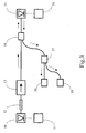
- Fig.1 shows a configuration of a known bidirectionally pumped optical fibre amplifier 100, comprising an amplifying doped optical fibre section 101, for example an erbium doped amplifying fibre, pump lasers 102, 103, WDM couplers 104, 105, optical isolators 106, 107 for light signals, input and output terminals 108, 109.
- a signal light is launched in the amplifier 100 through the input terminal 108, travels along the doped fibre section 101 to be amplified therein and exits through the output terminal 109.
- Suitable energy for amplification is provided by pump lasers 102, 103, which couple pump light to the doped fibre 101 through WDM couplers 104, 105.
- pump light from laser 102 is launched co-directionally in the doped fibre 101, that is in the same direction of the signal light
- pump light from laser 103 is launched counter-directionally, that is, in the opposite direction with respect to the signal light.
- pump lasers 102, 103 may emit light whose wavelength is comprised in a pumping band centered around 980 nm or 1480 nm.
- the expressions "co-directionally”, “counter-directionally”, “co-propagating”, “counter-propagating” will be always referred to the propagation direction of the signal light.
- the configuration shown in fig.1 has a problem in that the residual pump light from each pump laser, not fully absorbed by the amplifying fibre, is injected into the opposite pump laser, which can result in optical instabilities and fluctuations in amplification of the optical signal.
- each pump injection fibre includes a photorefractive pump filter constituting part of the resonant cavity of the associated pump laser, the two pump filters being mutually different to give rise to an offset between the two pumping bands.
- the two pumping bands are preferably offset by several nanometers.
- the pump filters are photorefractive gratings having a determined pitch and thus a determined central wavelength for reflection: the use of such a grating makes it possible simultaneously to reduce the width of the pumping band and to position said band more accurately within the spectrum.
- a pump laser even without a stabilizing grating, can have a stable optical emission if it is injected by an external radiation having a wavelength close to the free running wavelength of the injected laser and having a sufficiently high power.
- a locking of the optical emission of the injected laser around the wavelength of the injection takes place.
- the useful "locking bandwidth", that is, the useful difference between the injected wavelength and the free running wavelength of the injected laser may range up to several nanometers.
- Stability of the optical emission means that at least 80% of the power emitted by the injected laser is comprised in a wavelength range of about 2 nm around the wavelength of the injection.
- a pump residual due to a pump radiation not absorbed in an active fibre said pump radiation coming from a first pump laser used with a stabilizing grating, may have a sufficient power for stably locking the optical emission of a second pump laser, used without a stabilizing grating.
- the first laser acts as a master and the second laser acts as a slave, in a master-slave configuration, achieving bidirectional pumping of the amplifying fibre with a pump light having the same wavelength traveling co and counter-directionally.
- the invention relates to a method for pumping an optical amplifier comprising an active optical fibre, a first pump laser and a second pump laser, the method comprising:
- the difference between the free running wavelength of the second pump laser and said predetermined wavelength is lower than 18 nm, more preferably lower than 8 nm, even more preferably lower than 5 nm.
- said predetermined wavelength and said free running wavelength are comprised between 968 nm and 986 nm.
- a first power ratio between an output power of the second pump laser and a power of the first pump residual is lower than 15 dB, more preferably lower than 10 dB, even more preferably lower than 8 dB.
- the locked emission wavelength of the second pump laser is comprised in an emission bandwidth of at least 0.5 nm. In a further embodiment, the locked emission wavelength of the second pump laser is comprised in an emission bandwidth of about 2 nm.
- the invention relates to a bidirectionally pumped optical amplifier comprising:
- the first pump branch further comprises an optical isolator for the pump radiation.
- the difference between said predetermined wavelength and the free running wavelength of the second laser is lower than 18 nm, more preferably lower than 8 nm, even more preferably lower than 5 nm.
- said predetermined wavelength and said free running wavelength are comprised between 968 nm and 986 nm.
- a power ratio between an output power of said second laser and a power of said pump residual is lower than 15 dB, more preferably lower than 10 dB, even more preferably lower than 8 dB.
- the locked emission wavelength of the second laser is comprised in an emission bandwidth of at least 0.5 nm.
- the locked emission wavelength is comprised in an emission bandwidth of about 2 nm.
- a length of said active fibre is lower than 15 m.
- an output power of at least one of the first and second pump lasers is higher than 15 mW, more preferably higher than 50 mW, even more preferably higher than 100 mW.
- the bidirectionally pumped optical amplifier according to the second aspect of the invention further comprises a feedback system for at least regulating the output power of the first and second pump lasers.
- the selective reflector is a grating, more preferably a fibre grating.
- the first and second lasers are semiconductor lasers.
- the semiconductor lasers are AlGaAs-InGaAs lasers.
- an optical amplifier comprises a pre-amplifying section, including at least one active fibre and at least one pump laser, and a booster section, including a bidirectionally pumped optical amplifier according to the second aspect of the invention.
- an optical amplifier comprising a bidirectionally pumped optical amplifier according to the second aspect of the invention may be included along the optical transmission path of an optical transmission system comprising at least one transmitter and at least one receiver, coupled to said optical transmission path.
- the optical transmission system is a WDM system.
- the invention in a third aspect, relates to a method for stabilizing the optical emission of a laser having a predetermined output power and a predetermined free running wavelength, the method comprising: injecting into said laser a radiation having a wavelength comprised in a predetermined locking band around said free running wavelength, said injecting radiation having a sufficient power for thereby locking the optical emission of the laser around the wavelength of said injecting radiation, characterized in that the width of said locking band is at least 0.5 nm.
- the width of the locking band is lower than 15 nm.
- a power ratio between the output power of the laser and the power of the injected radiation is lower than 15 dB, more preferably lower than 10 dB, even more preferably lower than 8 dB.
- the bandwidth of the locked optical emission is at least 0.5 nm. In a further embodiment, the bandwidth of the locked optical emission is about 2 nm. Typically, the said locked optical emission is multi-longitudinal mode.
- said free running wavelength is comprised between 968 and 986 nm.
- EDFAs Erbium Doped Fibre Amplifiers
- fig.2 shows an embodiment of an optical amplifier 10 comprising a pre-amplifying section 11 and a booster section 12, comprised between an input terminal 13 and an output terminal 14, the two sections 11,12 being separated by an ASE filter 15.
- the pre-amplifier section 11 is a double stage optical amplifier, comprising two erbium doped fibres (EDFs) 111, 111', separated by an isolator 112; pump light is furnished to the EDFs through WDM couplers 115, 116, respectively by pump lasers 113, 114.
- the booster section 12 is a bidirectionally pumped optical amplifier, comprising an EDF 121 pumped co- and counter-directionally by two pump lasers 122, 123, through WDM couplers 124, 125 respectively.
- lasers 113, 114 were 980 nm pump lasers.
- Two signal channels in the 1550 nm band having total power of -12 dBm were inserted through the input terminal 13, amplified to reach a power level of 9.5 dBm after the first EDF 111 and a power level of 12.7 dBm after the second EDF 111'.
- the wavelengths of the channels were 1545 nm and 1558 nm.
- pump lasers 122, 123 in the wavelength range around 980 nm were used for the booster section; in a second test, pump lasers 122, 123 in the wavelength range around 1480 nm were used; in a third test, only one laser 122, generating co-propagating pump light in the wavelength range of 980 nm was used.
- the absorption coefficient of the EDF was about 5 dB/m for a wavelength around 1550 nm.
- the length of the EDF 121 was 10 m.
- bidirectional pumping is more effective at 980 nm with respect to 1480 nm.
- Table 1 clearly shows that bidirectional pumping at 980 nm is advantageous also in terms of SNR and, significantly, in terms of flatness of the gain curve. In order to evaluate flatness, the difference between P 1545 and P 1558 was considered.
- the absorption band of the EDF ranges from about 968 nm to about 986 nm, whereas the gain spectrum of a 980 nm semiconductor pump laser is typically 60 nm wide.
- unabsorbed residual pump from one laser can be injected in the other laser, inducing instabilities in the optical emission of the latter.
- a power meter 58 and an optical spectrum analyzer 59 were connected to two ports of a second 2x1 single mode fibre coupler 57 for 980 nm while a third port of the second 2x1 fibre coupler 57 was connected to a third port of the first 2x1 fibre coupler 54, in order to measure optical emission (total power and spectrum) from the second laser 55.
- the fibre grating 52 was set for stabilizing the emission of the first laser 50 around 971 nm.
- the reflectivity of the grating 52 was of about 5% and its bandwidth was of about 0.5 nm.
- the power ratio in the arms of the first and second 2x1 fibre couplers 54, 57 was 80/20.
- Lasers 50, 55 used for the experiment were E2 pump modules for terrestrial applications, produced by the Applicant.
- Optical isolator 53 was a 980 nm optical isolator, produced by Tokin, having an insertion loss of 1.2 dB and an extinction ratio of 30 dB.
- the free running wavelength of the non-stabilized second laser 55 ranged from about 974 to about 976 nm.
- emission from first laser 50 is stabilized in a well defined wavelength range around 971 nm, travels through isolator 53 and coupler 54 and is injected in second laser 55.
- Emission from second laser 55 is splitted by coupler 54, so that 80% of the emitted power is sent towards the power meter 58 and the spectrum analyzer 59.
- Optical isolator 53 also blocks emitted power from laser 50 back-reflected by coupler 54. In such way, optical emission from first laser 50 is completely stable.
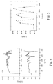
- Fig.4 shows the results of some measurements made with the setup of fig.3.
- fig.4 shows a comparison between the slope of the power per driving current (P-I) curve of the second laser 55 respectively when the first laser 50 is switched off (fig.4a) and when the first laser 50 is switched on (fig.4b), causing an injected power of 1.2 mW to reach the second laser 55.
- the slope of the P-I curve is plotted versus the pumping current I applied to the second laser 55.
- fig.4a when the first laser 50 is switched off, that is, when no injected power reaches the second laser 55, small oscillations are present in the curve around a mean value of the slope of the P-I curve of about 0.08 W/A.
- Fig.5 shows the corresponding plot of the emitted wavelength of the second laser 55 in the same conditions of fig.4b, that is, with an injected power of 1.2 mW from the first laser 50 to the second laser 55.
- the plot of the wavelength is shown versus the pumping current I of the second laser 55.
- oscillations between the free running wavelength (974-976 nm) and the wavelength of the emitted light of the grating-stabilized first laser 50 (971 nm) occur, in correspondence to the kinks seen in fig.4a.
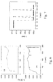
- fig.6a, 6b show the result of an experiment in which a grating centered around a wavelength value of 975 was added in front of second laser 55.
- the grating 52 in front of the first laser 50 was centered around a wavelength value of 977 nm.
- fig.6a shows the slope of the P-I curve of the second laser 55 when first laser 50 is switched off
- fig.6b shows the slope of the P-I curve of the second laser 55 when first laser 50 is switched on and a power of 5 mW is injected towards second laser 55.
- kinks appear at current values around 130 mA and 180 mA.
- Fig.7 shows the corresponding plot of the emitted wavelength of the second laser 55, in the same conditions described for fig.6b: as it can be seen, as long as the current is below about 50 mA, the emitted stabilized wavelength of the second laser 55 is centered around a value of 977 nm (that is the wavelength of the stabilizing grating of the first laser), whereas for greater current values the emitted power is mainly confined around a wavelength value of 975 nm (that is the wavelength of the stabilizing grating of the second laser), but oscillations are still present for current values around 75 mA and 120 mA. In this case, instabilities in the spectrum and in the P-I curve are induced for an injected power more than four times higher than in the case of second laser not grating-stabilized (5 mW versus 1.2 mW).
- a result obtained by the Applicant is that the wavelength emission of a pump laser may be stably confined in a bandwidth not lower than about 0.5 nm around the center wavelength of the external injection.
- This optical stabilization is performed without need of an external stabilizing grating in front of the laser itself.
- the above indicated large emission bandwidth normally assures multi-longitudinal-mode operation of the injected pump laser.
- the useful "locking bandwidth" that can be defined as the maximum difference in wavelength between the free running wavelength of the injected laser and the wavelength of the injection that ensures the locking may be of several nanometers. In particular, the higher the injected power the wider the locking bandwidth.
- the grating-stabilized pump laser acts as a "master” and the non-stabilized pump laser acts as a "slave”, in a master-slave configuration.
- the locking conditions depend on the injected power and on the power emitted by the injected laser. Applicant has determined that a stable optical emission of the injected laser may be ensured if the injected power is preferably chosen so that the ratio between the output power of the injected laser and the injected power is lower than 15 dB. More preferably, the above ratio should be lower than 10 dB, even more preferably lower than 8 dB.
- the useful locking bandwidth may reach values of 10-15 nm.
- the minimum locking bandwidth is determined by the spectral width of the injection.
- the spectral width of the injection is determined by the bandwidth of the stabilizing grating of the master laser. Typical values of bandwidth of the gratings used with pump lasers are of about 0.5 nm.
- the obtained locked optical emission bandwidth of the injected laser typically results to be higher than 0.5 nm and may reach values of about 2 nm.
- the stability of the emitted wavelength is evaluated by calculating the normalized power in band (PIB) around the wavelength value ⁇ 1 of the locking radiation, that is the function
- PIB normalized power in band
- the above function PIB is the ratio of the power emitted by the laser in a wavelength range of two nm centered on the wavelength ⁇ 1 , versus the total power emitted.
- a PIB of at least 0.8 is sufficient to say that the laser operates in optically stable regime around the wavelength value ⁇ 1 , that is the emission of the laser is stably locked on the wavelength of the injection, in a bandwidth of about two nm.
- a suitable grating 52 to be put in front of the injecting laser 50 depending on the power of the injecting radiation.
- Such grating should be centered on a wavelength value comprised in a range which depends on the injected power.
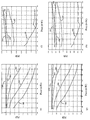
- Figs.8a and 8b show the obtained plots of the PIB versus total power emitted P out of the injected laser, that is the second laser 55 (see fig.3), with an injected power of 5 mW.
- Each of the different curves relates to a different grating used for stabilizing first laser 50.
- the following table 2 resumes the link between the curves shown in figs.8a to 8h and the wavelength of the gratings used.
- fig.8a comprises curves obtained using gratings centered on wavelengths lower than or equal to the threshold wavelength of the injected laser (976 nm)
- fig.8b comprises curves obtained using gratings centered on wavelengths greater than or equal to the threshold wavelength of the injected laser.
- Curve 304 is reported both in fig.8a and in fig.8b as it relates to a sort of "borderline grating".
- Figs. 8c and 8d show the plot of the PIB versus the output power of the injected laser for an injected power P inj of 10 mW.
- the different curves relates to the different gratings used, as in previous figures.
- the number of curves or curve sections that exceeds 0.8 of PIB is higher than in the previous case.
- curves 304, 305, 306, 307 exceed 0.8 in the whole operative range of output power shown; moreover, curve 303 exceeds 0.8 as long as the output power is below 100 mW.
- the correspondence between curves reference numbers and grating wavelength can be found in the above table 2. According to figs.
- a stabilized emission of a laser having a threshold wavelength of 976 nm can be obtained if the injected radiation is in a wavelength range comprised between 976 and 982 nm: the stabilized emission can be performed in the whole operative range of output power of the laser itself. If the output power of the laser is maintained below 100 mW, the interval can be extended up to 974 nm. In such a way, the emission of the injected laser is mainly locked in a two nm interval around the wavelength of the injected radiation, according to the definition of PIB above mentioned.
- Figs. 8e and 8f show the plot as explained in the previous figures for an injected power of 15 mW.
- Fig.9 shows a plot of the PIB of the externally injected laser 55, emitting an output power of 120 mW, versus the difference between the wavelength of the injected radiation ⁇ 1 (that is the center wavelength of the grating 52) and the threshold wavelength of the injected laser ⁇ th .
- this difference in wavelength we will refer to this difference in wavelength to as a "detuning" of the grating with respect to the threshold wavelength of the laser.
- Fig.9 is based on the results shown in figures 8a to 8h, as it was derived by taking the intersections of the different curves in figures 8a to 8h with the value of output power of 120 mW and then joining the so-determined dots with segments.
- curve 400 was derived by taking such intersections from figures 8a-8b and refers to an injected power of 5 mW;
- curve 401 was derived by taking the intersections from figures 8c-8d and refers to an injected power of 10 mW;
- curve 402 was derived by taking the intersections from figures 8e-8f and refers to an injected power of 15 mW;
- curve 403 was derived by taking the intersections from figures 8g-8h and refers to an injected power of 20 mW.
- the value PIB 0.8 is highlighted.
- the detuning range grows as the injected power grows. At 5 mW of injected power, the detuning range is only about 3 nm wide, whereas at 20 mW of injected power the detuning range is about 14 nm wide, ranging from about 971-972 nm to 985-986 nm (which is very close to the amplitude of the 980 pump window of an EDF).
- ⁇ FRW is the free running wavelength of the injected laser at 120 mW of output power.
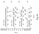
- Figures from 10a to 10d show the results of a series of experiments made by the Applicant, using the experimental setup already described with reference to fig.3, in order to confirm the simulation results above described with reference to fig.9 and table 3.
- first laser 50 was stabilized with a grating centered around a wavelength of about 971 nm
- second laser 55 was left non-stabilized.
- the free running wavelength of the second laser 55 ranged between 973.5 nm and 976 nm.
- the different figures show the plot of the wavelength emission of the second laser 55, versus applied current, with different values of injected power P inj coming from first laser 50.
- fig.10d shows the plot of the wavelength for an injected power P inj of 22 mW: as it can be seen, no wavelength oscillations are present.
- the tested case corresponds to the third line of table 3, the detuning being of about -2.5 nm: in such case, the corresponding injected power to be used for locking the emission of the laser should be, according to table 3, of 15 mW for a total emitted power of 120 mW.
- a total emitted power of 120 mW corresponds, in figs. 10a to 10d, to an applied current of about 220 mA.
- Fig.11 schematically shows a preferred embodiment of a bidirectionally pumped optical amplifier 200.
- Optical amplifier 200 comprises an active fibre 201 and pump lasers 202, 203 comprised in pump branches 220, 230.
- WDM couplers 204, 205 are connected to the ends of the active fibre 201, for coupling in the active fibre 201 a pump radiation coming from lasers 202, 203.
- Input and output terminals 208, 209 respectively allow the insertion of an optical signal to be amplified in the optical amplifier 200 and the dropping of the amplified optical signal from the optical amplifier 200.
- Active fibre 201 is preferably an erbium doped fibre.
- the absorption coefficient of the active fibre 201 is about 5 dB/m at 1550 nm.
- the length of the active fibre 201 is preferably lower or equal to 15 m.
- Pump lasers 202, 203 preferably emit in the 980 nm window, that is, in a range comprised between 968 and 986 nm.
- the power emitted by at least one of the pump lasers 203, 203 is higher than 15 mW, more preferably higher that 50 mW, even more preferably, higher than 100 mW.
- Preferred embodiments of pump lasers suitable to be used in optical amplifier 200 are AlGaAs-InGaAs based semiconductor lasers.
- At least one optical isolator for the optical signal is typically added in the optical amplifier 200: in the embodiment of fig.11, two optical isolators 206, 207 are present.
- a wavelength selective reflector 210 (in the following, for brevity, "selective reflector") is added in one of the pump branches 220 for stabilizing the emitted wavelength of the enclosed laser 202.
- Selective reflector 210 has a low reflectivity, typically lower than about 10%, preferably lower than or equal to about 7%. Its bandwidth is typically of about 0.5 nm around a predetermined center wavelength.
- selective reflector 210 is a grating, even more preferably a fibre grating.
- a selective reflector 210 is added in front of laser 202, generating co-propagating pump radiation.
- the center wavelength of the selective reflector 210 is about 977 nm.
- the second laser 203 has no selective reflector and thus it is not wavelength-stabilized.
- An optical isolator 211 for the pump radiation may also be added in the pump branch 220 comprising the wavelength-stabilized pump laser 202.
- wavelength-stabilizing selective reflector 210 and optical isolator 211 are added in the pump branch 230, enclosing laser 203 which generates counter-propagating pump radiation, whereas laser 202, generating co-propagating pump radiation, is not wavelength-stabilized.
- a control system as a feedback system, not shown in fig.11, is typically added in order to control the operative conditions of the amplifier 200, that is, its amplifying range.
- the control system can accurately set the output power of the pump lasers 202, 203 depending on the amplifier specifications.
- the feedback system comprises a coupler, for example a 99:1 coupler, after the output of the amplifier 200, that allows to extract from the line a small portion of the amplified signal light.
- suitable devices well known in the art, such as a photodetector and a control electronics, the latter being also connected to the pump laser 202, 203, for controlling the driving currents thereof.
- an optical signal is inserted in the optical amplifier 200 through input terminal 208, is amplified in the active fibre 201 and exits through output terminal 209.
- the optical signal may be, for example, a single channel or a collection of channels traveling in a WDM system, of which optical amplifier 200 is a part.
- Energy for optical amplification is given by pump lasers 202, 203.
- Pump radiation from first laser 202 is coupled co-directionally in the active fibre 201 by means of first WDM coupler 204.
- Pump radiation from second laser 203 is coupled counter-directionally in the active fibre 201 by means of second WDM coupler 205.
- a first pump residual coming from unabsorbed co-propagating pump radiation may reach the second WDM coupler 205 and be coupled towards the second pump laser 203.
- the emission wavelength of the second laser 203 may be locked by the residual, with a stable optical emission.
- the power of the pump residual should be preferably chosen in such a manner as the ratio between the output power of the second laser 203 and the injected power is lower than 15 dB, more preferably lower than 10 dB, even more preferably lower than 8 dB.
- the difference between the free-running wavelength of the second laser 203 and the center wavelength of the selective reflector 210 is preferably lower than 18 nm, more preferably lower than 8 nm, even more preferably lower than 5 nm.
- the power of the first pump residual is related to the operative conditions of the optical amplifier 200: in particular, it is related to the output power of the first pump laser 202.
- a second pump residual coming from unabsorbed counter-propagating pump radiation may reach the first WDM coupler 204 and be coupled towards the first pump laser 202.
- This second pump residual is advantageously blocked by the optical isolator 211, so that optical emission from first laser 202 can be maintained stabilized. If the power of the second pump residual is kept sufficiently low with respect to the output power of the module comprising laser 202 and selective reflector 210, the optical isolator 211 may be eliminated. A low residual power is not sufficient for triggering instability in the optical emission of first laser 202.
- the power of the second pump residual is related to the operative conditions of the optical amplifier 200: in particular, it is related to the output power of the second pump laser 203.
- active fibre 201 is pumped co-directionally by the first pump laser 202, the emission of which is stabilized by means of selective reflector 210, and counter-directionally by the second laser 203, the emission of which is in turn stabilized by exploiting locking effect due to residual pump injection.
- Active fibre 201 was an OLA-2 erbium doped fibre, produced by the Applicant, having a coefficient of absorption ⁇ of 5.16 dB/m for a wavelength around 1550 nm; first pump laser 202 and grating 210 were included in a laser+grating LTA2 module, produced by the Applicant, stabilized for emission at 977 nm; second pump laser 203 was an E2 laser module, having a free running wavelength ranging from 978 to 981 nm (in dependence of applied current), produced by the Applicant; isolator 211 was a 980 nm optical isolator, produced by Tokin; WDM couplers 204, 205 were 980/1550 nm couplers, produced by E-TEK.
- the grating 210 was a fibre grating having reflectivity of about 5% and bandwidth of 0.5 nm around the center wavelength of 9
- P1 res is the pump residual power as measured when the second laser 203 is switched off.
- the actual first pump residual power becomes higher, due to contribution of the counter-directional pump radiation to the population inversion in the active fibre 201.
- a length of the active fibre longer than 10 m leads in the tested example to residual powers that may be not sufficient to ensure locking of the emitted wavelength of the second laser 203.
- residual powers of sufficient entity were reached: thus, locking of the wavelength of the second laser 203 was ensured and high output power from the amplifier 200 was obtained.
- the range of P1 res ensuring locking of the wavelength of the second laser 203 depends on various factors (like the laser gain curve or the output power of the amplifier, for example) and can be determined during the setup of the amplifier 200, for example by setting the feedback/control system in order to maintain the correct value of residual power for any output power of the second laser 203 (that is by properly regulating output power of the first laser 202). It has to be noted that the value of P1 res measured when the second laser is switched off can be used as a conservative value for the whole life of the amplifier: as said, the actual residual power when the second laser 203 is switched on becomes higher, so the locking effect is always ensured.
- the feedback/control system can check and regulate the correct output powers of the two pump lasers in order to maintain the wavelength locking of the second laser 203.
- a further test was performed, by eliminating the optical isolator 211.
- Optical stability of the emission of the first laser 202 was ensured when the second residual pump (due to unabsorbed pump radiation coming from second laser 203 entering in pump branch 220) was maintaned under values up to 5 mW.
- the second residual pump due to unabsorbed pump radiation coming from second laser 203 entering in pump branch 220
- a first residual pump towards the first laser 202 of less than 5 mW was measured and no optical instability of the emission of the laser + grating module was observed.
- the feedback/control system has to check that the pump residual towards the laser+grating module is maintained under a safety value.
- safety value can be for example the minimum residual power which does not cause instability in the laser+grating module measured when no optical signal is inserted at the input 208 of the optical amplifier 200. This is because when an optical signal travels and is amplified in active fibre 201, the residual pump is lower than the case of no optical signal travelling.
- the minimum residual power above mentioned is a conservative value.
- the feedback/control system can act on the output power of the locked laser 203, taking care of maintaining the locking condition as above explained.
- the use of the optical isolator 211 allows to simplify the control circuit of the feedback/control system.
- Fig.12a and 12b show the measured emission spectrum from the second pump laser 203, respectively in a non-wavelength-stabilized condition and when locked by external injection.
- the shown spectra were taken during the test with the optical amplifier setup above described with reference to fig.11.
- fig.12a shows the free emission spectrum of the second pump laser 203 at an output power of 160 mW. Small oscillations along the curve are due to the plural longitudinal modes.
- Fig. 12b shows the emission spectrum of the second laser 203 when injected by the residual unabsorbed pump radiation coming from the first laser 202: output power of the first laser 202 was 130 mW, output power of the second laser 203 was 160 mW, output power of the amplifier was 20.1 dBm.
- the optical emission was modified by the injection, to be substantially confined in a range of less than two nm around 977 nm. In this wavelength range, multi-longitudinal-mode operation is still present.
- the peak around 977 nm was represented in fig.12b as "cut" around a value of 0 dBm, in order to highlight the longitudinal modes, in particular their spectral width.
- a bidirectionally pumped optical amplifier 200 as shown in fig.11 can be advantageously used in an optical transmission system, comprising at least one transmitter for emitting an optical signal, an optical transmission path, including at least one bidirectionally pumped optical amplifier according to the invention, and at least one receiver of said optical signal.
- the optical transmission system is a WDM transmission ist 500 comprising a plurality of transmitters 501, a plurality of receivers 502, a wavelength combiner 503, a wavelength demultiplexer 504, and an optical transmission path 505.
- the WDM system 500 also encloses one or more optical amplifier(s) 506 coupled along the optical transmission path 505.
- At least one optical amplifier 506 comprises a bidirectionally pumped optical amplifier according to the invention.
- the transmitters 501 are adapted for emitting optical signals at a different wavelength.
- the signals are coupled by the combiner 503 along the optical transmission path 505, amplified by the optical amplifier(s) 506, separated by the demultiplexer 504 according to their wavelength and sent each to the respective receiver 502.
- the wavelength of the signals is typically comprised in a range between 1520 and 1620 nm.
- a bidirectionally pumped optical amplifier according to the invention can be advantageously used as a booster section 12 of an optical amplifier 10 as shown in fig.2, in an optical transmission system.
- it may be advantageously used for boosting channels comprised in the C-band (1520 nm - 1560 nm) of a WDM series of channels.
Priority Applications (2)
| Application Number | Priority Date | Filing Date | Title |
|---|---|---|---|
| EP00114411A EP1170838A1 (de) | 2000-07-05 | 2000-07-05 | Optischer Verstärker mit bidirektionalem Pumpen |
| US10/091,093 US6628454B1 (en) | 2000-07-05 | 2002-03-04 | Optical amplifier with two directional pumping |
Applications Claiming Priority (2)
| Application Number | Priority Date | Filing Date | Title |
|---|---|---|---|
| EP00114411A EP1170838A1 (de) | 2000-07-05 | 2000-07-05 | Optischer Verstärker mit bidirektionalem Pumpen |
| US10/091,093 US6628454B1 (en) | 2000-07-05 | 2002-03-04 | Optical amplifier with two directional pumping |
Publications (1)
| Publication Number | Publication Date |
|---|---|
| EP1170838A1 true EP1170838A1 (de) | 2002-01-09 |
Family
ID=29585611
Family Applications (1)
| Application Number | Title | Priority Date | Filing Date |
|---|---|---|---|
| EP00114411A Withdrawn EP1170838A1 (de) | 2000-07-05 | 2000-07-05 | Optischer Verstärker mit bidirektionalem Pumpen |
Country Status (2)
| Country | Link |
|---|---|
| US (1) | US6628454B1 (de) |
| EP (1) | EP1170838A1 (de) |
Cited By (3)
| Publication number | Priority date | Publication date | Assignee | Title |
|---|---|---|---|---|
| US6618194B1 (en) * | 2000-07-05 | 2003-09-09 | Corning O.T.I. Spa | Optical amplifier with two directional pumping |
| US6628454B1 (en) * | 2000-07-05 | 2003-09-30 | Corning Oti Spa | Optical amplifier with two directional pumping |
| US6636346B2 (en) * | 2000-12-22 | 2003-10-21 | Nec Corporation | Optical amplifier and optically amplifying method |
Families Citing this family (5)
| Publication number | Priority date | Publication date | Assignee | Title |
|---|---|---|---|---|
| JP4113761B2 (ja) * | 2002-11-05 | 2008-07-09 | 富士通株式会社 | 光増幅装置 |
| KR100575953B1 (ko) * | 2003-10-27 | 2006-05-02 | 삼성전자주식회사 | 반사형 이득고정 반도체 광증폭기를 포함하는 광신호전송장치 및 이를 이용한 광통신 시스템 |
| WO2006078432A2 (en) * | 2005-01-18 | 2006-07-27 | Cyberkinetics Neurotechnology Systems, Inc. | Biological interface system with automated configuration |
| CN108963738A (zh) * | 2018-10-11 | 2018-12-07 | 中国人民解放军国防科技大学 | 一种双端输出的线性腔全光纤激光振荡器 |
| CN110707516A (zh) * | 2019-10-11 | 2020-01-17 | 中国船舶重工集团公司第七0七研究所 | 一种单程后向大功率输出的掺铒光纤光源 |
Citations (1)
| Publication number | Priority date | Publication date | Assignee | Title |
|---|---|---|---|---|
| US5640268A (en) * | 1995-02-28 | 1997-06-17 | Alcatel N.V. | Optical fiber amplifier with two directional pumping |
Family Cites Families (9)
| Publication number | Priority date | Publication date | Assignee | Title |
|---|---|---|---|---|
| US5768012A (en) * | 1997-03-07 | 1998-06-16 | Sdl, Inc. | Apparatus and method for the high-power pumping of fiber optic amplifiers |
| US5892781A (en) * | 1997-09-02 | 1999-04-06 | E-Tek Dynamics, Inc. | High output fiber amplifier/lasers for fiberoptic networks |
| US5991070A (en) * | 1997-11-14 | 1999-11-23 | Sdl, Inc. | Optical amplifier with oscillating pump energy |
| US5930029A (en) * | 1997-12-02 | 1999-07-27 | Sdl, Inc. | Optical fiber amplifier with optimized power conversion |
| JP3453301B2 (ja) * | 1998-04-27 | 2003-10-06 | 富士通株式会社 | 能動型光ファイバ及び光ファイバ増幅器 |
| US6327402B1 (en) * | 1999-02-04 | 2001-12-04 | Lucent Technologies, Inc. | Lightwave transmission system having wide pump wavebands |
| EP1170838A1 (de) * | 2000-07-05 | 2002-01-09 | Infineon Technologies AG | Optischer Verstärker mit bidirektionalem Pumpen |
| EP1170837A1 (de) * | 2000-07-05 | 2002-01-09 | Optical Technologies Italia S.p.A. | Optischer Verstärker mit bidirektionalem Pumpen |
| GB0031503D0 (en) * | 2000-12-22 | 2001-02-07 | Cit Alcatel | Optical amplifier |
-
2000
- 2000-07-05 EP EP00114411A patent/EP1170838A1/de not_active Withdrawn
-
2002
- 2002-03-04 US US10/091,093 patent/US6628454B1/en not_active Expired - Lifetime
Patent Citations (1)
| Publication number | Priority date | Publication date | Assignee | Title |
|---|---|---|---|---|
| US5640268A (en) * | 1995-02-28 | 1997-06-17 | Alcatel N.V. | Optical fiber amplifier with two directional pumping |
Non-Patent Citations (3)
| Title |
|---|
| GILES C R ET AL: "Simultaneous wavelength-stabilization of 980-nm pump lasers", IEEE PHOTONICS TECHNOLOGY LETTERS, AUG. 1994, USA, vol. 6, no. 8, pages 907 - 909, XP000465479, ISSN: 1041-1135 * |
| KIMURA T ET AL: "The 980 nm pump laser module with built-in isolator", OSA TRENDS IN OPTICS AND PHOTONICS. VOL.5 OPTICAL AMPLIFIERS AND THEIR APPLICATIONS, MONTEREY, CA, USA, 11-13 JULY 1996, 1996, Washington, DC, USA, Opt. Soc. America, USA, pages 164 - 167, XP000972561, ISBN: 1-55752-435-X * |
| KOBAYASHI S ET AL: "Injection locking characteristics in semiconductor lasers", ELECTRICAL COMMUNICATION LABORATORIES TECHNICAL JOURNAL, 1982, JAPAN, vol. 31, no. 12, pages 2215 - 2227, XP000712520, ISSN: 0415-3200 * |
Cited By (3)
| Publication number | Priority date | Publication date | Assignee | Title |
|---|---|---|---|---|
| US6618194B1 (en) * | 2000-07-05 | 2003-09-09 | Corning O.T.I. Spa | Optical amplifier with two directional pumping |
| US6628454B1 (en) * | 2000-07-05 | 2003-09-30 | Corning Oti Spa | Optical amplifier with two directional pumping |
| US6636346B2 (en) * | 2000-12-22 | 2003-10-21 | Nec Corporation | Optical amplifier and optically amplifying method |
Also Published As
| Publication number | Publication date |
|---|---|
| US20030169485A1 (en) | 2003-09-11 |
| US6628454B1 (en) | 2003-09-30 |
Similar Documents
| Publication | Publication Date | Title |
|---|---|---|
| US6700696B2 (en) | High order fiber Raman amplifiers | |
| Peng et al. | A tunable dual-wavelength erbium-doped fiber ring laser using a self-seeded Fabry-Perot laser diode | |
| Giles et al. | Simultaneous wavelength-stabilization of 980-nm pump lasers | |
| Oh et al. | Strong optical bistability in a simple L-band tunable erbium-doped fiber ring laser | |
| US6529317B2 (en) | L-band erbium-doped fiber amplifier pumped by 1530 nm-band pump | |
| JP3250428B2 (ja) | 光増幅装置 | |
| US20020176451A1 (en) | Erbium-doped fiber laser for long wavelength band | |
| US6606331B2 (en) | Step-tunable all-fiber laser apparatus and method for dense wavelength division multiplexed applications | |
| US6628454B1 (en) | Optical amplifier with two directional pumping | |
| US6738182B2 (en) | Optical fiber amplifier | |
| JP2001036169A (ja) | 双方向励起光増幅器 | |
| US6901085B2 (en) | Multi-wavelength ring laser source | |
| Harun et al. | Gain clamping in two-stage L-band EDFA using a broadband FBG | |
| US6728274B1 (en) | Multi-wavelength laser apparatus and method | |
| EP1170837A1 (de) | Optischer Verstärker mit bidirektionalem Pumpen | |
| JP2596620B2 (ja) | 光ファイバ増幅器 | |
| Lin et al. | Theory and experiments of a mode-beating noise-suppressed and mutually injection-locked Fabry-Perot laser diode and erbium-doped fiber amplifier link | |
| JP3273911B2 (ja) | 光ファイバ増幅器、励起用半導体レーザモジュールおよび光信号伝送システム | |
| EP1233490A2 (de) | Halbleiterlasermodul und Phaserverstärker und optisches Kommunikationssytem unter Verwendung desselben | |
| Harun et al. | Gain control in L-band erbium-doped fiber amplifier using a ring resonator | |
| Fake et al. | Optical amplifiers | |
| JP2003163396A (ja) | 光増幅器 | |
| CN212230769U (zh) | 一种单频窄线宽光纤激光器 | |
| WO2004038876A1 (en) | Bidirectionally pumped optical amplifier | |
| KR20050060674A (ko) | 직접 펌핑 구조의 광대역 광원 |
Legal Events
| Date | Code | Title | Description |
|---|---|---|---|
| PUAI | Public reference made under article 153(3) epc to a published international application that has entered the european phase |
Free format text: ORIGINAL CODE: 0009012 |
|
| AK | Designated contracting states |
Kind code of ref document: A1 Designated state(s): AT BE CH CY DE DK ES FI FR GB GR IE IT LI LU MC NL PT SE |
|
| AX | Request for extension of the european patent |
Free format text: AL;LT;LV;MK;RO;SI |
|
| AKX | Designation fees paid | ||
| REG | Reference to a national code |
Ref country code: DE Ref legal event code: 8566 |
|
| STAA | Information on the status of an ep patent application or granted ep patent |
Free format text: STATUS: THE APPLICATION IS DEEMED TO BE WITHDRAWN |
|
| 18D | Application deemed to be withdrawn |
Effective date: 20020710 |