EP1170733A2 - Rewritable optical recording medium and manufacturing method and apparatus therefor - Google Patents
Rewritable optical recording medium and manufacturing method and apparatus therefor Download PDFInfo
- Publication number
- EP1170733A2 EP1170733A2 EP01115652A EP01115652A EP1170733A2 EP 1170733 A2 EP1170733 A2 EP 1170733A2 EP 01115652 A EP01115652 A EP 01115652A EP 01115652 A EP01115652 A EP 01115652A EP 1170733 A2 EP1170733 A2 EP 1170733A2
- Authority
- EP
- European Patent Office
- Prior art keywords
- groove
- area
- segmented
- track
- recording medium
- Prior art date
- Legal status (The legal status is an assumption and is not a legal conclusion. Google has not performed a legal analysis and makes no representation as to the accuracy of the status listed.)
- Granted
Links
- 230000003287 optical effect Effects 0.000 title claims abstract description 50
- 238000004519 manufacturing process Methods 0.000 title claims description 13
- 238000000034 method Methods 0.000 claims description 12
- 230000001678 irradiating effect Effects 0.000 claims description 3
- 239000010410 layer Substances 0.000 description 7
- XKRFYHLGVUSROY-UHFFFAOYSA-N Argon Chemical compound [Ar] XKRFYHLGVUSROY-UHFFFAOYSA-N 0.000 description 6
- 238000010586 diagram Methods 0.000 description 6
- 239000000758 substrate Substances 0.000 description 4
- 229910052786 argon Inorganic materials 0.000 description 3
- 239000011521 glass Substances 0.000 description 3
- 238000003079 width control Methods 0.000 description 3
- 230000004075 alteration Effects 0.000 description 2
- 230000008859 change Effects 0.000 description 2
- 238000005520 cutting process Methods 0.000 description 2
- 238000011161 development Methods 0.000 description 2
- 238000005530 etching Methods 0.000 description 2
- 238000012986 modification Methods 0.000 description 2
- 230000004048 modification Effects 0.000 description 2
- 229920002120 photoresistant polymer Polymers 0.000 description 2
- 229920000515 polycarbonate Polymers 0.000 description 2
- 239000004417 polycarbonate Substances 0.000 description 2
- 229910000618 GeSbTe Inorganic materials 0.000 description 1
- 239000012790 adhesive layer Substances 0.000 description 1
- 230000002411 adverse Effects 0.000 description 1
- 238000004364 calculation method Methods 0.000 description 1
- 229910052681 coesite Inorganic materials 0.000 description 1
- 238000004590 computer program Methods 0.000 description 1
- 238000010276 construction Methods 0.000 description 1
- 238000012937 correction Methods 0.000 description 1
- 229910052906 cristobalite Inorganic materials 0.000 description 1
- 230000007423 decrease Effects 0.000 description 1
- 230000006870 function Effects 0.000 description 1
- 230000006872 improvement Effects 0.000 description 1
- 239000000463 material Substances 0.000 description 1
- 239000012782 phase change material Substances 0.000 description 1
- 238000000206 photolithography Methods 0.000 description 1
- 230000002265 prevention Effects 0.000 description 1
- 230000008569 process Effects 0.000 description 1
- 238000012545 processing Methods 0.000 description 1
- 230000009467 reduction Effects 0.000 description 1
- 230000003252 repetitive effect Effects 0.000 description 1
- 238000004904 shortening Methods 0.000 description 1
- 239000000377 silicon dioxide Substances 0.000 description 1
- VYPSYNLAJGMNEJ-UHFFFAOYSA-N silicon dioxide Inorganic materials O=[Si]=O VYPSYNLAJGMNEJ-UHFFFAOYSA-N 0.000 description 1
- 238000009751 slip forming Methods 0.000 description 1
- 229910052682 stishovite Inorganic materials 0.000 description 1
- 230000001360 synchronised effect Effects 0.000 description 1
- 229910052905 tridymite Inorganic materials 0.000 description 1
Images




Classifications
-
- G—PHYSICS
- G11—INFORMATION STORAGE
- G11B—INFORMATION STORAGE BASED ON RELATIVE MOVEMENT BETWEEN RECORD CARRIER AND TRANSDUCER
- G11B7/00—Recording or reproducing by optical means, e.g. recording using a thermal beam of optical radiation by modifying optical properties or the physical structure, reproducing using an optical beam at lower power by sensing optical properties; Record carriers therefor
- G11B7/24—Record carriers characterised by shape, structure or physical properties, or by the selection of the material
- G11B7/26—Apparatus or processes specially adapted for the manufacture of record carriers
- G11B7/261—Preparing a master, e.g. exposing photoresist, electroforming
-
- G—PHYSICS
- G11—INFORMATION STORAGE
- G11B—INFORMATION STORAGE BASED ON RELATIVE MOVEMENT BETWEEN RECORD CARRIER AND TRANSDUCER
- G11B7/00—Recording or reproducing by optical means, e.g. recording using a thermal beam of optical radiation by modifying optical properties or the physical structure, reproducing using an optical beam at lower power by sensing optical properties; Record carriers therefor
- G11B7/007—Arrangement of the information on the record carrier, e.g. form of tracks, actual track shape, e.g. wobbled, or cross-section, e.g. v-shaped; Sequential information structures, e.g. sectoring or header formats within a track
Definitions
- the present invention relates to a rewritable optical recording medium and a manufacturing method and apparatus therefor. More particularly, the present invention relates to a rewritable optical recording medium and manufacturing method and apparatus therefor in which data can be recorded by the user and illegal recording and reproduction of data are disabled.
- Optical recording media such as a write-once DVD-R (Digital Versatile Disc - Recordable) and a rewritable DVD-RW (DVD - Re-recordable) are being put into practical use or under further development.
- the discs have a recording capacity of a few gigabytes (GB) and data can be recorded by the user thereon.
- High-volume data copying can be made with almost no loss of data quality due to the remarkable improvement in performance of the large-capacity digital optical recording media as mentioned above and a recording and reproducing apparatus.
- Fig. 1 is a diagram showing a layout of a physical sector in the radial direction on the recording surface of a recorded DVD-ROM (DVD - Read Only Memory). Information data is recorded in an information area. A lead-in area, a data area, and a lead-out area are sequentially provided along the radial direction from a start point of the information area (i.e., start point of the physical sector).
- the lead-in area includes data for reproduction of the disc such as a reference code, control data for configuring a reproduction control data signal, and the like as shown in Fig. 2.
- a control data area is constructed by 192 ECC (Error Correction Code) blocks.
- ECC Error Correction Code
- constructions of the ECC blocks in the control data area are shown by using relative sector numbers 0 to 15.
- Each of the contents in those ECC blocks are the same control data.
- 192 control data of the same contents are sequentially and repetitively recorded.
- the ECC block consists of 16 sectors. There is recorded in each ECC block important information regarding copy protection including physical format information, disc manufacturing information, and contents provider information.
- the control data regarding reproduction is recorded into the control data area in the lead-in area when the information data is recorded.
- the reproducing apparatus reads the data and executes reproduction of the recorded information data such as video data and the like on the basis of the read information.
- the data in the DVD-ROM disc is RF-copied (i.e., a read signal (RF signal) is recorded as it is by a recording circuit without being subjected to signal processing) into the rewritable DVD-RW disc and the control data is illegally falsified
- an illegal DVD-RW disc which cannot be distinguished from the DVD-ROM disc i.e., an exact or a dead copy of the DVD-ROM disc
- development of a copy protection technique is an important subject to prevent a false or illegal copy of the recorded data such as video/audio data, a computer program, or the like.
- the present invention is made in consideration of the foregoing problems and it is an object of the present invention to provide a rewritable optical recording medium which prevents illegal recording and reproduction of information data and manufacturing method and apparatus therefor.
- a rewritable optical recording medium on which a land track and a groove track for recording a data signal are formed which comprises a segmented groove area in which the groove track is segmented along a rotating direction of the optical recording medium by groove non-forming portions to form a plurality of groove portions; and a continuous groove area in which a continuous groove is formed, the continuous groove having a groove width smaller than a groove width in the segmented groove area.
- a method of manufacturing a master disc for a rewritable optical recording medium having a land track and a groove track for recording a data signal by irradiating a laser beam on the master disc which comprises the steps of forming a segmented groove track having a plurality of groove portions in a first area of the optical recording medium along a rotating direction of the optical recording medium; and forming, in a second area of the optical recording medium, a continuous groove track having a groove width smaller than a groove width of the first area.
- Fig. 3 is a perspective view schematically showing a structure of a recording surface of a conventional DVD-RW disc.
- an optical disc (DVD-RW) 11 is a phase change type optical disc in which information data is rewritable and which has a multilayer 15 constructed by a recording layer made of a phase change material (for example, GeSbTe) serving as a data recording layer and a protecting layer made of a glass material (ZnS-SiO 2 ) which sandwiches the recording layer.
- Groove tracks 12 and land tracks 13 are formed thereon.
- the groove tracks 12 serve as information recording tracks and land tracks 13 serve as guide tracks for guiding a laser beam (B) on the groove track 12 for reproduction or recording.
- the optical disc also has a reflecting layer 16 for reflecting the laser beam (B) when recorded data is reproduced and an adhesive layer 19 for adhering those layers on a transparent substrate (polycarbonate) 18. Further, a transparent substrate (polycarbonate) 17 for protecting the layers is provided on the beam incidence surface of the disc.
- Prepits 14 corresponding to pre-information are formed on the land track 13.
- the prepits 14 carry the pre-information which is used by an information recording/reproducing apparatus upon recording or reproduction.
- the pre-information includes an address information for recognizing a position on the groove track 12 and sync information.
- the prepits 14 are formed prior to shipment of the optical disc 11.
- the groove track 12 has been wobbled at a frequency corresponding to a disc rotational speed.
- the groove tracks 12 are wobbled prior to shipment of the optical disc 11.
- the groove tracks 12 have a predetermined groove width and a predetermined groove depth and are formed at a predetermined track pitch.
- recording information data i.e., information data such as image information to be recorded other than the pre-information
- the wobbling frequency of the groove tracks 12 is extracted in the information recording apparatus for controlling the optical disc 11 to rotate at a predetermined rotational speed.
- the prepits 14 are preliminarily detected to obtain the pre-information.
- An optimum output of the laser beam (B) as a recording light is determined on the basis of the pre-information.
- Address information indicating a position on the optical disc 11 where the recording information data should be recorded are obtained on the basis of the pre-information.
- the recording information data is recorded at the corresponding recording position on the basis of the address information.
- the laser beam (B) is irradiated so that the beam center coincides with the center of the groove track 12 and recording information pits corresponding to the recording information data are formed on the groove track 12.
- a size of the light spot (SP) is set so that a part thereof is irradiated not only to the groove track 12 but also to the land track 13.
- the pre-information is detected from the prepits 14 by using a part of reflection light of the light spot (SP) irradiated on the land track 13 by, for example, a push-pull method, so that the pre-information is obtained.
- the push-pull method (a radial push-pull method) is executed using a photodetector divided or partitioned by a line that is parallel to the tangential direction of the groove track 12 (i.e., the rotating direction of the optical disc 11). Also, a wobble signal is extracted from the groove track 12, so that a clock signal for recording which is synchronized with the rotation of the disc is obtained.
- the recording information data to be recorded on the optical disc 11 has previously been divided every sync frame as an information unit.
- One recording sector is formed by 26 sync frames.
- One ECC block is formed by 16 recording sectors.
- One sync frame has a length which is 1488 times (1488T) as long as a channel bit length ("T") that is specified by a recording format at the time when the recording information data is recorded. Further, a head portion of a length of 32T of one sync frame is used as sync information SY for obtaining synchronization of every sync frame.
- the groove track 12 is wobbled at a predetermined wobbling frequency f0 (for example, 140 kHz) for all of the sync frames.
- a signal for rotation control of a spindle motor is detected and the clock signal for recording is generated by extracting the predetermined wobbling frequency f0.
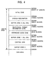
- Fig. 4 shows the details of a lead-in area of a DVD-RW disc.
- Data such as a reference code, control data, is included in the lead-in area.
- An RW-physical format information zone is provided and important control data for recording/reproduction control of the disc has been written as phase change pits in the zone.
- the groove track is formed in a segmented manner.
- Fig. 5 is a plan view schematically showing a boundary area of the buffer zone 1 and the control data zone on the DVD-RW disc according to the first embodiment of the present invention.
- the control data zone is a segmented groove area 21A (a first area) comprising segmented groove tracks 12A in which a plurality of groove portions 22A are formed in the rotating direction of the optical disc 11.
- the segmented groove track 12A comprises the groove portions 22A and groove non-forming portions (hereinafter, referred to as mirror portions) 25 where no groove is formed.
- Another area (a second area) such as buffer zone, or data area, etc.
- a non-segmented groove area (hereinafter, referred to as a continuous groove area) 21B comprising groove tracks (hereinafter, referred to as continuous groove tracks) 12B in which a groove has been continuously formed (i.e., the groove is not segmented).
- each groove portion 22A of the segmented groove track 12A comprises: a fundamental pit portion 23 serving as either one of a mark portion or a space portion; and an extension portion 24 of a groove having a predetermined length.
- the extension portion 24 is a groove portion that is appended continuously to the fundamental pit portion 23.
- the fundamental pit portion 23 carries a mark portion (or a space portion) while the extension portion 24 and the mirror portion 25 (groove non-forming portion) are included in a space portion (or mark portion).
- the segmented groove track 12A is formed by, for example, a method whereby a cutting light beam upon groove cutting is 8/16 modulated and an emitting power is controlled between on and off operation. More particularly, the groove track 12A has an intermittent structure segmented according to a signal of the same frequency band as that of a recording RF signal (i.e., recording signal obtained after 8/16 modulation) which is recorded on the optical disc by the optical disc recording/reproducing apparatus.
- a recording RF signal i.e., recording signal obtained after 8/16 modulation
- the fundamental pit portion 23 has a pit length corresponding to a mark (or space) of an 8/16 modulation signal S2 in a manufacturing apparatus, which will be explained hereinlater.
- the minimum pit length of the fundamental pit portion 23 is equal to 3T and the maximum pit length is equal to 11T (T: channel bit length).
- T channel bit length
- the maximum pit length is equal to 14T when a pit having a length 14T is used as a sync pattern.
- the extension portion 24 has a length of 3T ⁇ 0.73 based on an extension signal S3, which will be explained hereinlater.
- the segmented groove track 12A is formed so that the duty ratio of all the fundamental pit portions 23 included in the segmented groove track 12A is approximately 50%.
- Fig. 6 is a graph showing a photodetection signal level in the push-pull method (hereinafter, simply referred to as a push-pull signal level) to the length of extension portion 24.
- the groove portion 22A is formed by adding the extension portion 24 to the fundamental pit portion 23 to improve the push-pull signal level for tracking control.
- the push-pull signal level increases as the extension portion 24 becomes longer. Even if the groove track is formed in a segmented manner, the level of the reproduction RF signal increases by the repetitive recording of the same illegal control data, so that the prevention of the recorded data reading becomes imperfect. The illegal reading can be prevented by shortening the extension portion 24, however, the push-pull signal level decreases as mentioned above and an adverse influence is produced on tracking performance. This trade-off can be solved by optimizing the groove width of the groove portion 22A in addition to the length of the extension portion 24.
- the push-pull signal level changes in accordance with the groove width.
- the push-pull signal level reaches a maximum value at a value near a half (i.e., 0.37 ⁇ m) of the track pitch (0.74 ⁇ m). Therefore, the groove width should be determined to lie within a range from the groove width (0.26 ⁇ m) of the continuous groove track 12B to a half (i.e., 0.37 ⁇ m) of the track pitch (0.74 ⁇ m).
- the length of extension portion 24 should be determined to have a value such that the signal level which does not affect the reproducing operation in consideration of an increased amount of the signal level which is compensated by the increase of the groove width mentioned above.
- Fig. 8 shows the RF signal level due to the intermittence of the groove track as a function of the groove width.
- the fundamental pit portion carries data obtained by the 8/16 modulation and the extension portion 24 has a length of 3T ⁇ 0.73.
- the RF signal level that is caused due to the segmented groove track becomes a maximum value at a groove width which is slightly smaller than a half (i.e., 0.37 ⁇ m) of the track pitch (0.74 ⁇ m). To prevent the illegal reproduction, therefore, the groove width of the groove portion 22A is determined so as to increase the RF signal level.
- an optical disc in which the reduction of the push-pull signal level can be avoided and the illegal recording and reproduction can be prevented by determining the groove width of the groove portion 22A, the length of extension portion 24, and the track pitch as mentioned above.
- a duty ratio or the like of the fundamental pit portion 23 can be properly changed in consideration of the photodetection signal level.
- the groove width and the length of each groove portion can be determined in accordance with the duty ratio of the groove portion of the segmented groove track in a manner similar to that in the foregoing first embodiment.
- the segmented groove track 12A is divided by the signal of the same band as that of the recording RF signal for the optical disc, it can also be segmented by a signal including a part of the band of the recording RF signal. Further, the prepits can also be constructed on the land track.
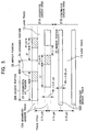
- FIG. 9 is a block diagram showing a configuration of a manufacturing apparatus 30 of a master disc of an optical disc.
- a photoresist 41B is coated on a glass substrate 41A serving as a master disc of the DVD-RW disc and patterned through a conventional photolithography and etching process.
- a dummy control data signal S1 to form the segmented groove track 12A is generated in a recording signal generating circuit 31.
- the generated dummy data signal S1 is 8/16 modulated in an 8/16 modulator 32.
- the extension signal S3 used to extend a mark portion of the 8/16 modulation signal S2 by 3T ⁇ 0.73 is generated in an extension signal generating circuit 40.
- the extension signal S3 is added to the modulation signal S2 in an adding circuit 42 and an addition signal S4 is supplied to a power control circuit 33.
- a groove width control signal S6 to set the width of groove portion to 0.31 ⁇ m is supplied from a controller 34 to the power control circuit 33.
- the power control circuit 33 generates a laser power control signal S8 on the basis of the addition signal S4 and a power control signal S7.
- the power control signal S8 is supplied to an AO (acousto-optic) modulator 38 through an AO driving circuit 39.
- the AO modulator 38 turns on/off the laser beam from an argon laser 37 on the basis of the addition signal S4 and adjusts a light power of the laser beam on the basis of the groove width control signal S6.
- the control signal S6 for setting the width of grooves to 0.26 ⁇ m and the control signal S7 to make the laser beam to be continuously irradiated are supplied from the controller 34 to the power control circuit 33.
- the AO modulator 38 therefore, allows the laser beam emitted from the argon laser 37 to pass through irrespective of the addition signal S4 and adjusts the laser beam power on the basis of the groove width control signal S6.
- a wobble signal generating circuit 35 generates a wobble signal S9 of a sine wave shape to form a wobble to the groove track irrespective of the irradiation area of the laser beam and supplies the signal to a frequency modulator 36.
- the supplied wobble signal is frequency modulated by the frequency modulator 36, so that a predetermined frequency modulation signal S10 (for example, signal whose center frequency is equal to 140 MHz and which changes in a range from 139 MHz to 141 MHz) is generated.
- the frequency modulation signal S10 is supplied to the AO modulator 38 through the AO driving circuit 39.
- the AO modulator 38 controls an emitting direction of the laser beam from the argon laser 37 on the basis of the frequency modulation signal.
- the control signal S8 since a power of the laser beam which is supplied to the AO modulator 38 is controlled by the control signal S8, the photoresist 41B is exposed by the laser beam from the AO modulator 38, so that it is possible to form a resist pattern for forming the wobbled segmented groove track 12A having the groove width 0.31 ⁇ m and the wobbled continuous groove track 12B having the groove width 0.26 ⁇ m.
- a master disc for an optical disc having the segmented groove tracks and the continuous groove tracks can be formed by etching a master disc glass substrate 41 on which the resist pattern has been formed.
- the optical recording media mentioned above can be manufactured by using the master disc.
- the optical recording medium and a manufacturing method and apparatus therefor, which can prevent the illegal recording and reproduction of data from the disc.
Landscapes
- Engineering & Computer Science (AREA)
- Manufacturing & Machinery (AREA)
- Optical Recording Or Reproduction (AREA)
- Optical Record Carriers And Manufacture Thereof (AREA)
- Manufacturing Optical Record Carriers (AREA)
Abstract
Description
Claims (11)
- A rewritable optical recording medium on which a land track and a groove track for recording a data signal are formed, comprising:a segmented groove area in which the groove track is segmented along a rotating direction of said optical recording medium by groove non-forming portions to form a plurality of groove portions; anda continuous groove area in which a continuous groove is formed, said continuous groove having a groove width smaller than a groove width in said segmented groove area.
- The medium according to claim 1, wherein the groove width in said segmented groove area is smaller than a half of a groove track pitch.
- The medium according to claim 1, wherein the groove width in said segmented groove area is determined so as to maximize a read signal level from said segmented groove area.
- The medium according to claim 1, wherein a frequency band of a reproduction signal from the segmented groove track includes at least a part of a frequency band of a data signal which is recorded on said optical recording medium.
- The medium according claim 1, wherein said segmented groove area is a control data recording area for recording a reproduction control data signal.
- A method of manufacturing a master disc for a rewritable optical recording medium having a land track and a groove track for recording a data signal by irradiating a laser beam on the master disc, comprising the steps of:forming a segmented groove track having a plurality of groove portions in a first area of said optical recording medium along a rotating direction of said optical recording medium; andforming, in a second area of said optical recording medium, a continuous groove track having a groove width smaller than a groove width of said first area.
- The method according to claim 6, wherein the groove width in said first area is smaller than a half of a groove track pitch.
- The method according to claim 6, wherein the groove width in said first area is determined so as to maximize a read signal level from said segmented groove area.
- The method according to claim 6, wherein a frequency band of a reproduction signal from the segmented groove track includes at least a part of a frequency band of a data signal which is recorded on said optical recording medium.
- The method according to claim 6, wherein said first area is a control data recording area for recording a reproduction control data signal.
- An apparatus of manufacturing a master disc for a rewritable optical recording medium having a land track and a groove track for recording a data signal by irradiating a laser beam on the master disc, comprising:means for forming a segmented groove track having a plurality of groove portions in a first area of said optical recording medium along a rotating direction of said optical recording medium; andmeans for forming, in a second area of said optical recording medium, a continuous groove track having a groove width smaller than a groove width in said first area.
Applications Claiming Priority (2)
| Application Number | Priority Date | Filing Date | Title |
|---|---|---|---|
| JP2000205328 | 2000-07-06 | ||
| JP2000205328A JP4361198B2 (en) | 2000-07-06 | 2000-07-06 | Rewritable optical recording medium, manufacturing method and manufacturing apparatus thereof |
Publications (3)
| Publication Number | Publication Date |
|---|---|
| EP1170733A2 true EP1170733A2 (en) | 2002-01-09 |
| EP1170733A3 EP1170733A3 (en) | 2003-01-15 |
| EP1170733B1 EP1170733B1 (en) | 2009-04-08 |
Family
ID=18702435
Family Applications (1)
| Application Number | Title | Priority Date | Filing Date |
|---|---|---|---|
| EP01115652A Expired - Lifetime EP1170733B1 (en) | 2000-07-06 | 2001-07-03 | Rewritable optical recording medium and manufacturing method and apparatus therefor |
Country Status (5)
| Country | Link |
|---|---|
| US (2) | US6618350B2 (en) |
| EP (1) | EP1170733B1 (en) |
| JP (1) | JP4361198B2 (en) |
| CN (1) | CN1198275C (en) |
| DE (1) | DE60138246D1 (en) |
Cited By (1)
| Publication number | Priority date | Publication date | Assignee | Title |
|---|---|---|---|---|
| EP1204105A3 (en) * | 2000-11-01 | 2004-07-21 | Pioneer Corporation | Rewritable type optical disc, manufacturing method and manufacturing system therefor |
Families Citing this family (8)
| Publication number | Priority date | Publication date | Assignee | Title |
|---|---|---|---|---|
| EP1049095A3 (en) * | 1999-04-28 | 2006-06-28 | Victor Company Of Japan, Ltd. | Information recording medium and reproducing apparatus therefor |
| US6678236B1 (en) * | 1999-08-24 | 2004-01-13 | Victor Company Of Japan, Ltd. | Information recording medium method and apparatus for recording and reproducing information |
| ATE382936T1 (en) * | 1999-11-16 | 2008-01-15 | Sony Corp | RECORDING MEDIUM, DATA RECORDING METHOD AND APPARATUS, DATA REPRODUCTION METHOD AND APPARATUS |
| FR2813139B1 (en) * | 2000-08-21 | 2002-11-29 | Commissariat Energie Atomique | WRITING / READING DEVICE OF DIGITAL DATA WITH OPTICAL CONTROL |
| JP2002313031A (en) * | 2001-04-12 | 2002-10-25 | Nec Corp | Optical disk having identification performance |
| JP2004079078A (en) * | 2002-08-19 | 2004-03-11 | Nec Corp | Optical recording medium, information recording method thereof, and recording apparatus |
| CN1306504C (en) * | 2002-08-29 | 2007-03-21 | 联发科技股份有限公司 | Laser power control method and device for optical recording system |
| US20080285429A1 (en) * | 2003-12-03 | 2008-11-20 | Koninklijke Philips Electronics N.V. | Side-Channel for Record Carriers with Spiral Tracks |
Family Cites Families (17)
| Publication number | Priority date | Publication date | Assignee | Title |
|---|---|---|---|---|
| US4985881A (en) * | 1983-12-23 | 1991-01-15 | Hitachi, Ltd. | Record carrier for a magneto-optical disc memory having guide grooves of a plurality of tracks disposed with a predetermined relation to light spot diameter |
| JPS60261043A (en) * | 1984-06-07 | 1985-12-24 | Victor Co Of Japan Ltd | Information recording medium disc |
| US5553051A (en) * | 1987-09-04 | 1996-09-03 | Hitachi, Ltd. | Increased intensity optical recording medium with adjacent grooves of different optical depth and a method and apparatus for reproducing the same |
| US5402411A (en) * | 1992-03-05 | 1995-03-28 | Fujitsu Limited | Constant amplitude of tracking error signals generated from a head guide track and a performed track |
| US5452284A (en) * | 1992-09-14 | 1995-09-19 | Matsushita Electric Industrial Co., Ltd. | Optical recording/reproducing medium and apparatus using land and groove encoded information signals and identification signals including position information |
| JP2697555B2 (en) * | 1993-05-26 | 1998-01-14 | 松下電器産業株式会社 | Optical information recording medium |
| JP2776230B2 (en) * | 1993-12-24 | 1998-07-16 | 日本ビクター株式会社 | optical disk |
| JPH08241539A (en) * | 1995-03-03 | 1996-09-17 | Hitachi Ltd | Optical disk substrate, manufacturing method thereof, and optical disk device |
| JPH08306080A (en) * | 1995-04-28 | 1996-11-22 | Sony Corp | Information recording medium and its molding die |
| JPH0981968A (en) * | 1995-09-14 | 1997-03-28 | Victor Co Of Japan Ltd | Phase change optical disc |
| US5851251A (en) * | 1996-05-17 | 1998-12-22 | Victor Company Of Japan, Ltd. | Manufacturing methods of optical disc and blank master |
| JPH1173686A (en) * | 1997-08-28 | 1999-03-16 | Ricoh Co Ltd | Optical storage medium |
| JP3489415B2 (en) * | 1997-10-15 | 2004-01-19 | 三菱化学株式会社 | Optical information recording medium |
| JPH11328738A (en) * | 1998-05-19 | 1999-11-30 | Nippon Columbia Co Ltd | Optical information recording medium |
| JP3374086B2 (en) * | 1998-08-28 | 2003-02-04 | 三洋電機株式会社 | Magneto-optical recording medium |
| JP2000187887A (en) * | 1998-12-24 | 2000-07-04 | Ricoh Co Ltd | optical disk |
| JP3543950B2 (en) | 1999-06-28 | 2004-07-21 | パイオニア株式会社 | Optical recording medium and method of manufacturing the same |
-
2000
- 2000-07-06 JP JP2000205328A patent/JP4361198B2/en not_active Expired - Fee Related
-
2001
- 2001-07-03 DE DE60138246T patent/DE60138246D1/en not_active Expired - Lifetime
- 2001-07-03 EP EP01115652A patent/EP1170733B1/en not_active Expired - Lifetime
- 2001-07-05 CN CNB011159952A patent/CN1198275C/en not_active Expired - Fee Related
- 2001-07-05 US US09/898,488 patent/US6618350B2/en not_active Expired - Lifetime
-
2003
- 2003-06-02 US US10/449,026 patent/US6837072B2/en not_active Expired - Fee Related
Cited By (2)
| Publication number | Priority date | Publication date | Assignee | Title |
|---|---|---|---|---|
| EP1204105A3 (en) * | 2000-11-01 | 2004-07-21 | Pioneer Corporation | Rewritable type optical disc, manufacturing method and manufacturing system therefor |
| US7230899B2 (en) | 2000-11-01 | 2007-06-12 | Pioneer Corporation | Rewritable type optical disc including recording marks over break portions of recording tracks, manufacturing method and manufacturing system therefor |
Also Published As
| Publication number | Publication date |
|---|---|
| US6837072B2 (en) | 2005-01-04 |
| US20020021658A1 (en) | 2002-02-21 |
| US6618350B2 (en) | 2003-09-09 |
| DE60138246D1 (en) | 2009-05-20 |
| CN1337690A (en) | 2002-02-27 |
| CN1198275C (en) | 2005-04-20 |
| EP1170733A3 (en) | 2003-01-15 |
| US20030198171A1 (en) | 2003-10-23 |
| EP1170733B1 (en) | 2009-04-08 |
| JP4361198B2 (en) | 2009-11-11 |
| JP2002025120A (en) | 2002-01-25 |
Similar Documents
| Publication | Publication Date | Title |
|---|---|---|
| JP4226204B2 (en) | Optical recording medium, manufacturing apparatus and manufacturing method thereof | |
| JP2002042347A (en) | Optical recording medium and device/method for manufacturing the same | |
| EP1065659B1 (en) | Optical recording medium and manufacturing method thereof | |
| EP1170733B1 (en) | Rewritable optical recording medium and manufacturing method and apparatus therefor | |
| EP1640980B1 (en) | Recording medium and apparatus and method for manufacturing the same | |
| US6687214B2 (en) | Recording medium and apparatus and method for manufacturing the same | |
| JP3543950B2 (en) | Optical recording medium and method of manufacturing the same | |
| JP2002260244A (en) | Optical recording medium | |
| HK1083149B (en) | Recording medium and apparatus and method for manufacturing the same | |
| HK1030831B (en) | Optical recording medium and manufacturing method thereof |
Legal Events
| Date | Code | Title | Description |
|---|---|---|---|
| PUAI | Public reference made under article 153(3) epc to a published international application that has entered the european phase |
Free format text: ORIGINAL CODE: 0009012 |
|
| AK | Designated contracting states |
Kind code of ref document: A2 Designated state(s): AT BE CH CY DE DK ES FI FR GB GR IE IT LI LU MC NL PT SE TR |
|
| AX | Request for extension of the european patent |
Free format text: AL;LT;LV;MK;RO;SI |
|
| PUAL | Search report despatched |
Free format text: ORIGINAL CODE: 0009013 |
|
| AK | Designated contracting states |
Kind code of ref document: A3 Designated state(s): AT BE CH CY DE DK ES FI FR GB GR IE IT LI LU MC NL PT SE TR |
|
| AX | Request for extension of the european patent |
Free format text: AL;LT;LV;MK;RO;SI |
|
| RIC1 | Information provided on ipc code assigned before grant |
Free format text: 7G 11B 7/007 A, 7G 11B 7/013 B |
|
| RIN1 | Information on inventor provided before grant (corrected) |
Inventor name: TAGIRI, TAKAO Inventor name: SASAKI, YOSHIO Inventor name: OSHIMA, SEIRO Inventor name: MURAMATSU, EIJI Inventor name: MARUYAMA, TOSHIHIKO Inventor name: KATO, MASAHIRO |
|
| 17P | Request for examination filed |
Effective date: 20030123 |
|
| AKX | Designation fees paid |
Designated state(s): DE FR GB |
|
| GRAP | Despatch of communication of intention to grant a patent |
Free format text: ORIGINAL CODE: EPIDOSNIGR1 |
|
| GRAS | Grant fee paid |
Free format text: ORIGINAL CODE: EPIDOSNIGR3 |
|
| GRAA | (expected) grant |
Free format text: ORIGINAL CODE: 0009210 |
|
| AK | Designated contracting states |
Kind code of ref document: B1 Designated state(s): DE FR GB |
|
| REG | Reference to a national code |
Ref country code: GB Ref legal event code: FG4D |
|
| REF | Corresponds to: |
Ref document number: 60138246 Country of ref document: DE Date of ref document: 20090520 Kind code of ref document: P |
|
| REG | Reference to a national code |
Ref country code: GB Ref legal event code: 746 Effective date: 20090528 |
|
| PLBE | No opposition filed within time limit |
Free format text: ORIGINAL CODE: 0009261 |
|
| STAA | Information on the status of an ep patent application or granted ep patent |
Free format text: STATUS: NO OPPOSITION FILED WITHIN TIME LIMIT |
|
| 26N | No opposition filed |
Effective date: 20100111 |
|
| REG | Reference to a national code |
Ref country code: FR Ref legal event code: PLFP Year of fee payment: 16 |
|
| REG | Reference to a national code |
Ref country code: FR Ref legal event code: PLFP Year of fee payment: 17 |
|
| REG | Reference to a national code |
Ref country code: FR Ref legal event code: PLFP Year of fee payment: 18 |
|
| PGFP | Annual fee paid to national office [announced via postgrant information from national office to epo] |
Ref country code: FR Payment date: 20190619 Year of fee payment: 19 |
|
| PGFP | Annual fee paid to national office [announced via postgrant information from national office to epo] |
Ref country code: DE Payment date: 20190618 Year of fee payment: 19 |
|
| PGFP | Annual fee paid to national office [announced via postgrant information from national office to epo] |
Ref country code: GB Payment date: 20190703 Year of fee payment: 19 |
|
| REG | Reference to a national code |
Ref country code: DE Ref legal event code: R119 Ref document number: 60138246 Country of ref document: DE |
|
| GBPC | Gb: european patent ceased through non-payment of renewal fee |
Effective date: 20200703 |
|
| PG25 | Lapsed in a contracting state [announced via postgrant information from national office to epo] |
Ref country code: FR Free format text: LAPSE BECAUSE OF NON-PAYMENT OF DUE FEES Effective date: 20200731 Ref country code: GB Free format text: LAPSE BECAUSE OF NON-PAYMENT OF DUE FEES Effective date: 20200703 |
|
| PG25 | Lapsed in a contracting state [announced via postgrant information from national office to epo] |
Ref country code: DE Free format text: LAPSE BECAUSE OF NON-PAYMENT OF DUE FEES Effective date: 20210202 |