EP1170647A2 - Method of correcting thermal displacement of machine tool - Google Patents
Method of correcting thermal displacement of machine tool Download PDFInfo
- Publication number
- EP1170647A2 EP1170647A2 EP01305838A EP01305838A EP1170647A2 EP 1170647 A2 EP1170647 A2 EP 1170647A2 EP 01305838 A EP01305838 A EP 01305838A EP 01305838 A EP01305838 A EP 01305838A EP 1170647 A2 EP1170647 A2 EP 1170647A2
- Authority
- EP
- European Patent Office
- Prior art keywords
- thermal displacement
- spindle
- feed shaft
- section
- displacement
- Prior art date
- Legal status (The legal status is an assumption and is not a legal conclusion. Google has not performed a legal analysis and makes no representation as to the accuracy of the status listed.)
- Granted
Links
Images





Classifications
-
- G—PHYSICS
- G05—CONTROLLING; REGULATING
- G05B—CONTROL OR REGULATING SYSTEMS IN GENERAL; FUNCTIONAL ELEMENTS OF SUCH SYSTEMS; MONITORING OR TESTING ARRANGEMENTS FOR SUCH SYSTEMS OR ELEMENTS
- G05B19/00—Program-control systems
- G05B19/02—Program-control systems electric
- G05B19/18—Numerical control [NC], i.e. automatically operating machines, in particular machine tools, e.g. in a manufacturing environment, so as to execute positioning, movement or co-ordinated operations by means of program data in numerical form
- G05B19/404—Numerical control [NC], i.e. automatically operating machines, in particular machine tools, e.g. in a manufacturing environment, so as to execute positioning, movement or co-ordinated operations by means of program data in numerical form characterised by control arrangements for compensation, e.g. for backlash, overshoot, tool offset, tool wear, temperature, machine construction errors, load, inertia
-
- B—PERFORMING OPERATIONS; TRANSPORTING
- B23—MACHINE TOOLS; METAL-WORKING NOT OTHERWISE PROVIDED FOR
- B23Q—DETAILS, COMPONENTS, OR ACCESSORIES FOR MACHINE TOOLS, e.g. ARRANGEMENTS FOR COPYING OR CONTROLLING; MACHINE TOOLS IN GENERAL CHARACTERISED BY THE CONSTRUCTION OF PARTICULAR DETAILS OR COMPONENTS; COMBINATIONS OR ASSOCIATIONS OF METAL-WORKING MACHINES, NOT DIRECTED TO A PARTICULAR RESULT
- B23Q3/00—Devices holding, supporting, or positioning work or tools, of a kind normally removable from the machine
- B23Q3/155—Arrangements for automatic insertion or removal of tools, e.g. combined with manual handling
- B23Q3/1552—Arrangements for automatic insertion or removal of tools, e.g. combined with manual handling parts of devices for automatically inserting or removing tools
- B23Q3/15526—Storage devices; Drive mechanisms therefor
- B23Q3/15534—Magazines mounted on the spindle
-
- G—PHYSICS
- G05—CONTROLLING; REGULATING
- G05B—CONTROL OR REGULATING SYSTEMS IN GENERAL; FUNCTIONAL ELEMENTS OF SUCH SYSTEMS; MONITORING OR TESTING ARRANGEMENTS FOR SUCH SYSTEMS OR ELEMENTS
- G05B2219/00—Program-control systems
- G05B2219/30—Nc systems
- G05B2219/49—Nc machine tool, till multiple
- G05B2219/49207—Compensate thermal displacement using measured distance
-
- G—PHYSICS
- G05—CONTROLLING; REGULATING
- G05B—CONTROL OR REGULATING SYSTEMS IN GENERAL; FUNCTIONAL ELEMENTS OF SUCH SYSTEMS; MONITORING OR TESTING ARRANGEMENTS FOR SUCH SYSTEMS OR ELEMENTS
- G05B2219/00—Program-control systems
- G05B2219/30—Nc systems
- G05B2219/49—Nc machine tool, till multiple
- G05B2219/49219—Compensation temperature, thermal displacement
-
- Y—GENERAL TAGGING OF NEW TECHNOLOGICAL DEVELOPMENTS; GENERAL TAGGING OF CROSS-SECTIONAL TECHNOLOGIES SPANNING OVER SEVERAL SECTIONS OF THE IPC; TECHNICAL SUBJECTS COVERED BY FORMER USPC CROSS-REFERENCE ART COLLECTIONS [XRACs] AND DIGESTS
- Y10—TECHNICAL SUBJECTS COVERED BY FORMER USPC
- Y10T—TECHNICAL SUBJECTS COVERED BY FORMER US CLASSIFICATION
- Y10T409/00—Gear cutting, milling, or planing
- Y10T409/30—Milling
- Y10T409/303752—Process
-
- Y—GENERAL TAGGING OF NEW TECHNOLOGICAL DEVELOPMENTS; GENERAL TAGGING OF CROSS-SECTIONAL TECHNOLOGIES SPANNING OVER SEVERAL SECTIONS OF THE IPC; TECHNICAL SUBJECTS COVERED BY FORMER USPC CROSS-REFERENCE ART COLLECTIONS [XRACs] AND DIGESTS
- Y10—TECHNICAL SUBJECTS COVERED BY FORMER USPC
- Y10T—TECHNICAL SUBJECTS COVERED BY FORMER US CLASSIFICATION
- Y10T409/00—Gear cutting, milling, or planing
- Y10T409/30—Milling
- Y10T409/303976—Milling with means to control temperature or lubricate
Definitions
- the present invention relates to a method of correcting thermal displacement in a machine tool.
- An object of the present invention is to provide a method of correcting thermal displacement in which thermal displacement can be corrected easily and at a low cost without the need for a sensor.
- a correction amount is determined for thermal displacement due to heat generated in a spindle motor and resultant heat conduction, in addition to thermal displacement due to heat generated by the rotation of a spindle.
- the tool position is corrected based on this correction amount.
- the correcting method of the first embodiment comprises: a step of detecting a spindle speed and a load of a spindle motor; a step of determining an average spindle speed and an average spindle motor load based on the spindle speed and the load of the spindle motor; a step of determining an amount of thermal displacement of a spindle portion based on the average spindle speed and the average spindle motor load; and a step of, by using an amount for canceling the amount of thermal displacement of the spindle portion as correction amount, correcting a position instruction value of a feed shaft of the machine tool based on the correction amount.
- a computational formula for computing the thermal displacement from the rotational speed of the spindle and the load of the spindle motor is determined in advance.
- the rotational speed of the spindle and the load of the spindle motor are monitored, and the monitored rotational speed of the spindle and load of the spindle motor are substituted into the computational formula, and a thermal displacement of a spindle and a thermal displacement due to heat generation of a spindle motor are determined, respectively.
- the spindle portion thermal displacement can be made to include not only the thermal displacement due to the amount of heat generated from the spindle and the spindle motor, but also, the thermal displacement due to the heat radiation and heat conduction caused in the tool portion.
- the entire stroke of the feed shaft is divided into a finite number of sections, and the thermal displacement of each section is used.
- a correction amount for the thermal displacement due to axial movement of the feed shaft is determined, and based on the determined correction amount, the tool position is corrected.
- the correction method of the second embodiment comprises: a step of dividing a range of movement of a feed shaft to set a plurality of sections; a step of detecting a position of the feed shaft; a step of determining an average moving speed at each section based on the detected position; a step of determining a thermal displacement at each section based on the average moving speed for each section; a step of adding the thermal displacement of each section from a reference position to a correction position, and using the sum as a feed shaft portion thermal displacement; a step of using the sum, which is obtained by adding the spindle portion thermal displacement to the feed shaft portion thermal displacement, as an overall thermal displacement at the correction position; and a step of using an amount, which cancels the overall thermal displacement, as a correction amount, and, in movement to the correction position of the feed shaft, effecting correction by adding the correction amount to a position instruction value of the feed shaft.
- the position of the feed shaft is monitored, and the average moving speed of the feed shaft at each section from the monitored position is determined of each section.
- the thermal displacement is determined.
- the correction amount at the correction position is determined. Based on the determined correction amount, the tool position is corrected.
- the computational formula may be a formula which includes thermal displacement due to heat radiation at each section and heat conduction from the adjacent section.
- the thermal displacement due to the feed shaft motor in addition to the thermal displacement of the feed shaft, is also considered.
- the feed shaft portion thermal displacement includes the displacement due to heat generation of the feed screw portion and the thermal displacement due to heat generated in the feed shaft motor.
- a correction amount for both thermal displacements is computed, and the position of the tool is corrected based on the correction amount.
- the thermal displacement correction method of the third embodiment in addition to the effects of heat generated in the feed shaft, the effects of heat generated in the feed shaft motor are considered, and accurate correction can be carried out.
- the results of correction are fed-back, and the thermal displacement computational formula is corrected.
- the thermal displacement determined in any of the above-described first through third embodiments and the displacement (correction error) determined from a deviation from an actual tool position the heat generation factor included in the thermal displacement computational formula is corrected, and the correction error is corrected.
- thermal displacement can be corrected simply and at a low cost, without the need for a sensor.
- Fig. 1 is a schematic view of a vertical type drill press 1 of a machine tool to which the present invention is applied.
- reference numeral 62 is a spindle motor
- 52 is a servo motor for a Z shaft which is a vertical feed shaft
- 10 is a numerical control device (CNC) which serves as a control device for controlling the drill press
- 64 is a spindle
- 66 is a tool mounted to a spindle 64B.
- the table T is moved in directions of an X shaft and a Y shaft, which are orthogonal to the Z shaft and perpendicular to one another, by unillustrated servo motors for the X shaft and Y shaft.
- the structure of the drill press 1 is no different than conventional structures, and thus, further explanation thereof will be omitted.
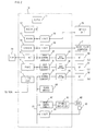
- Fig. 2 is a functional block diagram showing main portions of the numerical control device 10 of the above-described drill press.
- the interface 15 is an interface for external equipment which can be connected to the numerical control device 10.
- An external equipment 72 such as a paper tape reader or a paper tape puncher and an external storage device or the like, is connected to the interface 15.
- a machining program, the thermal displacement measurement program which will be described later, and the like, are read from the paper tape reader or the external storage device, and a machining program, which has been edited in the numerical control device 10, can be outputted to the paper tape puncher or external storage device.
- the current positions of the respective shafts of the drill press 1, alarms, parameters, and image signals such as image data and the like, are sent to the CRT/MDI unit 70, and are displayed on the display thereof.
- the CRT/MDI unit 70 is a manual data input device provided with a display and a keyboard and the like.
- An interface 18 receives data from the keyboard of the CRT/MDI unit 70, and transfers the data to the processor 11.
- An interface 19 is connected to a manual pulse generator 71, and receives pulses from the manual pulse generator 71.
- the manual pulse generator 71 is mounted to the operation panel of the drill press 1, and is used for accurately positioning movable portions of the machine tool 1 by control of the respective shafts by distributed pulses based on manual operation.
- the servo amplifiers 40-42 receive these instructions, and drive servo motors 50-52 of the respective shafts of the drill press 1.
- An encoder for position detection is included in each of the servo motors 50-52 of the respective shafts, and the position signal from the encoder is fed-back as a pulse train.
- a linear scale may be used as the position detector.
- F/V voltage/frequency
- a displacement measuring apparatus (detection switch) S which is mounted to the table T of the drill press 1 when thermal displacement data which will be described later is obtained, is connected to the I/O unit 17, and the ON/OFF state thereof can be confirmed by the processor 11 via the PC 16.
- the displacement measuring apparatus which can be positioned at any height, detects contact from the direction of Z axis of the distal end operation surface of the tool 66. As needed, a displacement measuring apparatus which detects contact from the direction of X axis of the outer peripheral operation surface of the tool 66, and a displacement measuring apparatus which detects contact from the direction of Y axis of the outer peripheral operation surface of the tool 66 can also be provided.
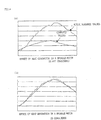
- Fig. 3A is a diagram of a thermal displacement curve showing the state of extension of the spindle and each shaft due to heat generated when the machine starts machining to drive the spindle and the feed shaft.
- Fig. 3A shows that the spindle and the feed shaft expand suddenly due to heat generation at an initial stage, and thereafter, as the amount of heat radiation comes near the amount of heat generation, the increase in the expansion becomes dull.
- Fig. 3B is a diagram of a thermal displacement curve showing the state of contraction of the spindle and the respective shafts due to heat radiation at the time when driving of the machine tool is stopped.
- Fig. 3B shows that when the machining is stopped and the movement stops, the spindle and the respective shafts contract due to heat radiation.
- thermal displacement which arises from heat generation due to rotation of the spindle and from heat generation due to conduction of the heat generated by driving the spindle motor, is determined.
- the thermal displacement of the spindle is expressed as a positional displacement of the Z axis
- the thermal displacement of the spindle is determined by measuring the positional displacement of the Z axis.
- the spindle motor In the measurement of the thermal displacement, the spindle motor is rotated at a predetermined rotational speed, and each time a predetermined interval of time passes, the height of the displacement measuring apparatus is adjusted, and the distal end operation surface of the tool is made to contact from the direction of Z axis, and the thermal displacement of the spindle is thereby measured.
- the measurement data a plurality of types of data can be determined by changing the rotational speed of the spindle motor or changing the mounted tool or the like.
- the computational formula for estimating the thermal displacement of the spindle is following formula (1).
- formula (1) By monitoring the rotational speed of the spindle from the measured data, formula (1) is established.
- ⁇ n ⁇ n-1 + A1 n - B1 n + C n-1
- C n C n-1 + A2 n - B2 n - ⁇ n-1
- n the sampling time
- A1 n in the above formula (1) is expressed by the following formula by using formula f1(S n ) expressing the average spindle rotational speed.
- A1 n K1 ⁇ f1(S n ) ⁇ ⁇ 1
- B1 n and B2 n in the above equation (1) correspond to expressing the thermal displacement curve illustrated in Fig. 3B as B ⁇ , and are expressed by the following formulas.
- B1 n k3 ⁇ n-1 ⁇ 3
- B2 n k4 ⁇ n-1 ⁇ 4
- ⁇ 3, ⁇ 4, k3, k4 are coefficients.
- the above coefficients ⁇ 1, ⁇ 2, ⁇ 3, ⁇ 4, k1, k2, k3, k4 can respectively be determined by the method of least squares so as to approximate the thermal displacement curve by measured data.
- the spindle portion thermal displacement ( ⁇ n ) is expressed by using the spindle average rotational speed S n and the spindle average motor load L n as parameters.
- the spindle portion thermal displacement ( ⁇ n ) is determined from the spindle average rotational speed (S n ) and the spindle average motor load (L n )
- the loads of the spindle motor can be determined by a load meter.
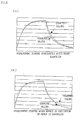
- Fig. 4 is an example of thermal displacement correction for the spindle and the spindle motor.
- (a) is a case where effects due to heat generated by the spindle motor are not considered, and compares the thermal displacement correction values for heat generated in the spindle, with actual measured values
- (b) is a case where the effects of heat generated in the spindle motor are considered, and compares, with actual measured values, the thermal displacement correction for heat generated in the spindle, as well as the thermal displacement correction for heat generated in the spindle motor. From Fig. 4, it can be seen that a substantially accurate approximation can be obtained by taking into consideration the effects of the heat generated in the spindle motor.
- the entire stroke of the feed shaft is divided into a finite number of sections, and thermal displacement correction for the feed shafts is carried out by using the thermal displacement for each of the divisional sections.
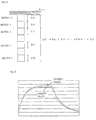
- Fig. 5 is a schematic diagram for explaining the divisional sections of the feed shaft.
- the entire stroke of the feed shaft is divided into X+1 sections, from a section 0 (a section adjacent to a reference position) to a section X (the section the furthest from the reference position).
- ⁇ nI ⁇ (n-1)I + A3 nI - B3 nI + D nI
- D nI k5 ⁇ (n-1)I+1 + ⁇ (n-1)I-1 - 2 ⁇ (n-1)I ⁇
- n the sampling time
- A3 nI K6 ⁇ f3(v nI ) ⁇ ⁇ 5
- the thermal displacement for each section obtained by dividing the movement range of the feed shaft is expressed by using the average moving speed of the feed shaft as a parameter.
- the position for each section of the feed shaft is detected, the average moving speed is determined from the changes of the positions, and the determined average moving speed is applied to the computational formula.
- the thermal displacement (feed shaft thermal displacement) L nX at a position X which arises from thermal displacement of the feed shaft is expressed by the following formula by adding the thermal displacement for each section I from the reference position until the position X.
- L nX ⁇ n0 + ⁇ n1 + ... + ⁇ nI + ... + ⁇ nX
- Fig. 6 shows that a substantially accurate approximation is achieved.
- the measurement of the thermal displacement of the feed shaft can be carried out by, for example, the processes shown in the flowchart of Fig. 7.
- the displacement measuring apparatus S whose height can be adjusted, is mounted on the table T, and the tool (an end mill or the like) 66, whose distal end is flat, is mounted on the spindle 64.
- a displacement measurement program is stored in the non-volatile memory 14 via the interface 15. The entire stroke of the Z axis for obtaining the thermal displacement data, the number I of divisions, the number of times measurement is carried out, and the like are set from the CRT/MDI unit 70, and an execution of the thermal displacement measurement program is instructed.
- step S1 a counter n which counts the number of times of measurement is set to "0"
- step S2 a counter I, which sets one of the sections obtained by dividing the entire stroke of the feed shaft is set, to "0"
- step S3 The position of the set section i is measured by the displacement measuring apparatus S (step S4). "1" is added to the counter i and the section is changed to the next set section i (step S5). The processings of steps S3, 4, 5 are repeated until the counter i becomes "I". In this way, positional data for all of the divisional sections is obtained (step S6).
- positional data for each of the divisional sections set by dividing the entire stroke of the feed shaft is determined. Then, based on the determined positional data for the respective divisional sections, the amount of movement for each divisional section is determined.
- the displacement due to heat generated by rotation of the feed screw of the feed shaft, and the displacement due to heat generation of a feed shaft motor are considered.
- the computational formula for thermal displacement correction in the present embodiment is obtained by adding, to the computational formula for thermal displacement correction of the above-described second embodiment, a term of the effects of heat conduction due to heat generated in the feed shaft motor.
- the effect of heat conduction due to heat generated in the feed shaft motor is greatest at the section which is adjacent to the feed shaft motor, among the respective divisional sections in the entire stroke of the feed shaft, and the effects in a section gradually decreases as the section goes away from the above-mentioned section adjacent to the feed shaft motor.
- the thermal displacement ⁇ n0 of this section can be expressed by the following formula in which a thermal displacement H due to the heat generated in the feed shaft motor is added to the above computational formula (8).
- ⁇ n0 ⁇ (n-1)0 + A3 n0 - B3 n0 + D n0 + H
- H in the above formula is a thermal displacement due to heat generated by the excitation of the feed shaft motor.
- the displacement H is a value ignoring the effects of other factors by assuming that the amount of heat generated in the feed shaft motor is low. However, when the amount of heat generated in the feed shaft motor is high, the following formula which takes the effects of other factors into consideration is effective.
- ⁇ n0 ⁇ (n-1)0 + A3 n0 - B3 n0 + D n0 + H n-1
- H n ⁇ (n-1)1 + (H n-1 + A4 n + B4 n ) - 2 ⁇ (n-1)0
- H n ⁇ (n-1)1 + (H n-1 + A4 n + B4 n ) - 2 ⁇ (n-1)0
- (a) is a case where measurement is started immediately after the power source is turned on
- (b) is a case where measurement is started when three hours elapsed after the power source is turned on and displacement due to heat generated by excitation of the feed shaft motor has already generated. In each case, it can been seen that a substantially accurate approximation is achieved.
- the thermal displacement of the spindle in the first embodiment is considered, in addition to the thermal displacement of the feed shaft in the above-described second and third embodiments. In this way, correction is carried out for both the thermal displacement of the spindle and the thermal displacement of the feed shaft.
- the thermal displacement of the spindle is expressed by the above formula (1)
- the thermal displacement of the feed shaft is expressed by the above formula (12).
- an overall thermal displacement ⁇ nX which considers both the thermal displacement of the spindle and the thermal displacement of the feed shaft, is expressed by the following formula which is obtained by adding formula (1) and formula (12).
- ⁇ nX ⁇ n + L nX
- the position of the feed shaft is detected (step S11).
- the thermal displacements of all of the sections are computed for each, for example, is (second) by using the thermal displacement computational formula of the first through fourth embodiments (step S12).
- the thermal displacement computed at that position is sent to a correcting means (step S13), and correction is carried out based on the thermal displacement.
- the correction processing can be carried out by storing a correction amount corresponding to the thermal displacement in a correction amount storing means, and by a function which adjusts the reference position, for example, a function for shifting an expanded external machine origin of the machine tool (step S14).
- step S15 The position detection to be carried out each 8ms (milliseconds), for example (step S15), and the processing (step S16) for computing the thermal displacement to be carried out every is (second), for example, are repeated (step S17) until the correction processing is completed.
- Fig. 11 is values obtained by actually measuring thermal displacements in a case where the correction processing is carried out when drill machining and tap machining are actually carried out. It can be seen from Fig. 11 that substantially accurate correction can be achieved.
- the thermal displacement is determined by computation according to the above-described first through fourth embodiments, and the thermal displacement is determined by actual measurement.
- the heat generation factor is corrected.
- the heat generation factor of the spindle is A1
- the heat generation factor of the feed shaft is A3
- the ratio ( ⁇ nX / ⁇ nX ) of the correction error ( ⁇ nX ) at time n and position X to the computed value ( ⁇ nX ) of the overall thermal displacement at position X is the error
- the ratio ( ⁇ nX / ⁇ n ) of the computed value ( ⁇ nX ) of the overall displacement at position X to the computed value ( ⁇ n ) of the overall thermal displacement of the entire spindle portion is the thermal displacement determined by computation
- the ratio(( ⁇ nX / ⁇ nX )/( ⁇ nX / ⁇ n )) of the above-mentioned error to the above-mentioned thermal displacement can be determined as the ratio ⁇ nX ⁇ n / ⁇ nX 2 .
- the heat generation factor A1' after correction can be expressed by the following formula by using this ratio.
- A1' A1 ⁇ (1 + ⁇ nX ⁇ n / ⁇ n
- the ratio ( ⁇ nX / ⁇ nX ) of the correction error ( ⁇ nX ) at time n and position X to the computed value ( ⁇ nX ) of the overall thermal displacement at position X is the error
- the ratio ( ⁇ nX /L nX ) of the computed value ( ⁇ nX ) of the overall displacement at position X to the computed value (L nX ) of the overall thermal displacement of the feed shaft from the reference point at position X is the thermal displacement determined by computation
- the ratio((L nX / ⁇ nX )/( ⁇ nX / ⁇ n )) of the above-mentioned error and the above-mentioned thermal displacement can be determined as the ratio ⁇ nX ⁇ L nX / ⁇ nX 2 .
- the heat generation factor A3' after correction can be expressed by the following formula by using this ratio.
- A3' A1 ⁇ (1 + ⁇ nX ⁇ L nX / ⁇ nX 2 ) Here;
- the position X at which correction is to be carried out is inputted, and the computed thermal displacement L nX from the reference point of the feed shaft at position X and the computed overall thermal displacement ⁇ n of the entire spindle portion are stored, for example, each 10 minutes, for a three-hour period. It should be noted that the measurement interval and the measurement time can be set arbitrarily.
- Fig. 12 shows the actual displacements in a case where drill machining and tap machining are carried out and the thermal displacements determined by computation are shown, and the difference therebetween shows the correction error, while (b) shows a case where the corrected heat generation factors determined based on the correction errors are used, and it can be seen that the error is substantially eliminated by correction.
- the actual amount of offset can be fed-back to the thermal displacement computational formula.
- appropriate correction for each case can be carried out.
Landscapes
- Engineering & Computer Science (AREA)
- Mechanical Engineering (AREA)
- Human Computer Interaction (AREA)
- Manufacturing & Machinery (AREA)
- Physics & Mathematics (AREA)
- General Physics & Mathematics (AREA)
- Automation & Control Theory (AREA)
- Automatic Control Of Machine Tools (AREA)
- Machine Tool Sensing Apparatuses (AREA)
- Numerical Control (AREA)
Abstract
Description
Claims (10)
- A method of correcting thermal displacement of a machine tool, comprising:detecting a speed of a spindle of a machine tool and a load of a spindle motor which drives the spindle;determining an average spindle speed and an average spindle motor load based on the speed of the spindle and the load of the spindle motor;determining an amount of thermal displacement of a spindle portion based on the average spindle speed and the average spindle motor load; andcorrecting a position instruction value for a feed shaft of the machine tool based on a correction amount, the correction amount being equivalent to an amount canceling the amount of thermal displacement of the spindle portion.
- The method of correcting thermal displacement of a machine tool according to claim 1, wherein the thermal displacement of the spindle portion includes a thermal displacement due to heat radiation and/or heat conduction by the machine tool.
- The method of correcting thermal displacement of a machine tool according to claim 1 or claim 2, wherein a thermal displacement of a spindle computational formula, in which the spindle speed and the spindle motor load are parameters, is prepared, and the thermal displacement of a spindle is determined by applying the average spindle speed and the average spindle motor load to the thermal displacement of a spindle computational formula.
- The method of correcting thermal displacement of a machine tool according to claim 1 or claim 2, wherein a thermal displacement of a spindle computational formula, in which the spindle speed and the spindle motor load are parameters, is prepared, and the thermal displacement of a spindle is determined by applying the average spindle speed and the average spindle motor load to the thermal displacement of a spindle computational formula, and
a heat generation factor in the thermal displacement computational formula is corrected based on an error between a thermal displacement and an actual displacement of a tool. - The method of correcting thermal displacement of a machine tool according to claim 1, whereina range of movement of the feed shaft is divided such that sections are set, and a position for each section of the feed shaft is detected,an average moving speed at each section is determined based on the detected positions,a thermal displacement at each section is determined based on the determined average moving speed,the thermal displacement of each section from a reference position to a correction position is added, and the sum is used as a feed shaft portion thermal displacement,the spindle portion thermal displacement is added to the feed shaft portion thermal displacement, and the sum is used as an overall thermal displacement at the correction position, andan amount which cancels the overall thermal displacement is used as a correction amount, and, in movement to the correction position of the feed shaft, correction is carried out by adding the correction amount to the position instruction value of the feed shaft.
- The method of correcting thermal displacement of a machine tool according to claim 5, wherein the thermal displacement of the section includes a thermal displacement due to heat radiation at that section and thermal conduction between that section and a section adjacent that section.
- The method of correcting thermal displacement of a machine tool according to claim 5, wherein the feed shaft portion thermal displacement includes a displacement due to heat generation of a feed screw portion and a thermal displacement due to heat generation of a feed shaft motor.
- The method of correcting thermal displacement of a machine tool according to claim 5, 6 or 7, wherein a feed shaft thermal displacement computational formula, in which a moving speed at a divisional section is a parameter, is prepared, and a thermal displacement of each section is determined by applying an average moving speed of each section to the feed shaft thermal displacement computational formula.
- The method of correcting thermal displacement of a machine tool according to claim 5, 6 or 7, wherein a feed shaft thermal displacement computational formula, in which a moving speed at a divisional section is a parameter, is prepared, and a thermal displacement of each section is determined by applying an average moving speed of each section to the feed shaft thermal displacement computational formula, and
a heat generation factor in the thermal displacement computational formula is corrected based on an error between a thermal displacement and an actual displacement of a tool. - A machine tool comprising:spindle speed detecting means for detecting a speed of a spindle;spindle motor load detecting means for detecting a load of a spindle motor;spindle portion thermal displacement computing means for determining a thermal displacement of a spindle portion based on an average spindle speed detected by the spindle speed detecting means and an average spindle motor load detected by the spindle motor load detecting means; andposition instruction correcting means for correcting a position instruction of a feed shaft of the machine tool by a value based on the thermal displacement determined by the spindle portion thermal displacement computing means.
Applications Claiming Priority (2)
| Application Number | Priority Date | Filing Date | Title |
|---|---|---|---|
| JP2000204570A JP3405965B2 (en) | 2000-07-06 | 2000-07-06 | Thermal displacement compensation method for machine tools |
| JP2000204570 | 2000-07-06 |
Publications (3)
| Publication Number | Publication Date |
|---|---|
| EP1170647A2 true EP1170647A2 (en) | 2002-01-09 |
| EP1170647A3 EP1170647A3 (en) | 2004-03-17 |
| EP1170647B1 EP1170647B1 (en) | 2005-12-28 |
Family
ID=18701811
Family Applications (1)
| Application Number | Title | Priority Date | Filing Date |
|---|---|---|---|
| EP01305838A Expired - Lifetime EP1170647B1 (en) | 2000-07-06 | 2001-07-06 | Method of correcting thermal displacement of machine tool |
Country Status (4)
| Country | Link |
|---|---|
| US (1) | US6471451B2 (en) |
| EP (1) | EP1170647B1 (en) |
| JP (1) | JP3405965B2 (en) |
| DE (1) | DE60116192T2 (en) |
Cited By (6)
| Publication number | Priority date | Publication date | Assignee | Title |
|---|---|---|---|---|
| EP1650620A3 (en) * | 2004-10-22 | 2007-04-18 | Yamazaki Mazak Corporation | Method and apparatus for correcting thermal displacement of machine tool |
| CN104942651A (en) * | 2014-03-31 | 2015-09-30 | 发那科株式会社 | Thermal displacement correction device for machine tool |
| US20150286208A1 (en) * | 2014-04-08 | 2015-10-08 | Fanuc Corporation | Thermal displacement correction device for machine tool |
| WO2015196222A1 (en) | 2014-06-24 | 2015-12-30 | Anton Paar Gmbh | Positioning unit |
| CN105312962A (en) * | 2014-07-03 | 2016-02-10 | 发那科株式会社 | Controller for machine tool |
| CN110717292A (en) * | 2019-09-29 | 2020-01-21 | 天津大学 | Heat generation power calculation method based on comprehensive working condition parameters of numerical control machine tool |
Families Citing this family (51)
| Publication number | Priority date | Publication date | Assignee | Title |
|---|---|---|---|---|
| US6671573B2 (en) * | 2000-12-14 | 2003-12-30 | Mitsubishi Denki Kabushiki Kaisha | Numerical controller and method for controlling the shaft of numeric controller |
| DE102004044838A1 (en) * | 2004-09-13 | 2006-03-30 | Chiron-Werke Gmbh & Co Kg | Method for compensation of thermal displacements |
| JP4469325B2 (en) * | 2005-11-04 | 2010-05-26 | 株式会社森精機製作所 | Thermal displacement correction device |
| EP1839806B1 (en) * | 2006-03-27 | 2009-04-29 | Fanuc Ltd | Automatic tool changing method and device for machine tool controlled by numerical controller |
| JP4891104B2 (en) * | 2007-01-29 | 2012-03-07 | オークマ株式会社 | Thermal displacement estimation method for machine tools |
| TWI318151B (en) * | 2007-02-09 | 2009-12-11 | Ind Tech Res Inst | Apparatus for detecting manufacturing parameters of a machine tool |
| JP4955451B2 (en) * | 2007-05-16 | 2012-06-20 | ヤマザキマザック株式会社 | Control method of compound lathe device, compound lathe device, blade position registration device, and blade position detection device |
| JP4538480B2 (en) * | 2007-09-07 | 2010-09-08 | 株式会社キラ・コーポレーション | Ball screw thermal displacement compensation method and NC machine tool executing the compensation method |
| JP4959508B2 (en) * | 2007-11-05 | 2012-06-27 | 三菱重工業株式会社 | Work processing method and behavior measuring device of machine tool |
| IT1390713B1 (en) * | 2008-07-11 | 2011-09-15 | Marposs Societa' Per Azioni | METHOD OF COMPENSATION OF THERMAL LEADS IN A POSITION SENSOR AND THERMICALLY COMPENSATED MEASUREMENT STATION |
| US8200172B2 (en) * | 2008-07-30 | 2012-06-12 | Monster Cable Products, Inc. | Look-up table for control of power output from FM transmitters |
| TW201021959A (en) * | 2008-12-11 | 2010-06-16 | Ind Tech Res Inst | A thermal error compensation method for machine tools |
| CN101887250B (en) * | 2009-05-12 | 2012-05-30 | 鸿富锦精密工业(深圳)有限公司 | CNC (Computerized Numerical Control) machine tool control device |
| JP5387838B2 (en) * | 2009-08-28 | 2014-01-15 | ブラザー工業株式会社 | Thermal displacement compensation method and thermal displacement compensation device for numerically controlled machine tool |
| JP5397095B2 (en) * | 2009-08-28 | 2014-01-22 | ブラザー工業株式会社 | Thermal displacement compensation method and thermal displacement compensation device for numerically controlled machine tool |
| JP5397096B2 (en) * | 2009-08-28 | 2014-01-22 | ブラザー工業株式会社 | Thermal displacement compensation method and thermal displacement compensation device for numerically controlled machine tool |
| US8294403B2 (en) * | 2009-09-04 | 2012-10-23 | Haas Automation, Inc. | Methods and systems for determining and displaying a time to overload of machine tools |
| JP5357082B2 (en) * | 2010-02-23 | 2013-12-04 | スター精密株式会社 | Machine tool control device and operation control method |
| TW201201951A (en) * | 2010-07-09 | 2012-01-16 | Hon Hai Prec Ind Co Ltd | Ultra-precision machining system and machining method |
| JP4917665B1 (en) * | 2010-11-11 | 2012-04-18 | ファナック株式会社 | Thermal displacement correction method and thermal displacement correction apparatus for machine tool |
| DE102010054393A1 (en) * | 2010-12-07 | 2012-06-14 | Chiron-Werke Gmbh & Co. Kg | Method for determining the position of a tool |
| JP5568005B2 (en) * | 2010-12-28 | 2014-08-06 | オークマ株式会社 | Apparatus and method for correcting thermal displacement of machine tool |
| JP5502912B2 (en) | 2012-01-19 | 2014-05-28 | ファナック株式会社 | Machine tool thermal displacement compensation device |
| JP5462296B2 (en) | 2012-02-13 | 2014-04-02 | ファナック株式会社 | Machine tool warm-up operation control device |
| JP5607695B2 (en) * | 2012-09-13 | 2014-10-15 | ファナック株式会社 | Machine tool thermal displacement compensation device |
| CN104619461B (en) * | 2012-10-01 | 2016-05-04 | 山崎马扎克公司 | machine tool |
| DE102013201751A1 (en) * | 2013-02-04 | 2014-08-07 | Otto Bihler Handels-Beteiligungs-Gmbh | Method for increasing the reliability of a feed axis and Achsansteuerungseinrichtung |
| JP5698798B2 (en) * | 2013-06-24 | 2015-04-08 | ファナック株式会社 | Machine tool with thermal displacement compensation function |
| TWI535522B (en) * | 2013-12-25 | 2016-06-01 | 財團法人工業技術研究院 | Apparatus and method for providing feedback force and machine tool system |
| JP5837148B1 (en) | 2014-06-18 | 2015-12-24 | ファナック株式会社 | Machine tool thermal displacement compensation device |
| US10088826B2 (en) * | 2014-08-20 | 2018-10-02 | Ford Global Technologies, Llc | CNC machine thermal growth characterization and thermal compensation correction |
| CN106488828B (en) | 2014-10-29 | 2017-12-29 | 山崎马扎克公司 | Machine tool equipped with thermal displacement correction amount setting and changing device |
| JP2016097459A (en) * | 2014-11-19 | 2016-05-30 | ファナック株式会社 | Rotary shaft center position measuring jig, and rotary shaft center position measuring method using the jig |
| JP6042917B2 (en) | 2015-01-30 | 2016-12-14 | ファナック株式会社 | Machine tool thermal displacement compensation device |
| JP6267152B2 (en) * | 2015-04-14 | 2018-01-24 | ファナック株式会社 | Tool conveying apparatus and processing system provided with gripping force measuring means of tool holding means of tool magazine |
| JP6285396B2 (en) * | 2015-07-17 | 2018-02-28 | ファナック株式会社 | Thermal displacement correction device that automatically determines the necessity of actual measurement of machine tools |
| JP2017024108A (en) | 2015-07-21 | 2017-02-02 | ファナック株式会社 | Machine tool thermal displacement correction apparatus |
| JP6396380B2 (en) * | 2016-09-06 | 2018-09-26 | ファナック株式会社 | Position correction system and position correction method for tool changer |
| US10730155B2 (en) * | 2016-09-09 | 2020-08-04 | Makino Milling Machine Co., Ltd. | Machine tool with manual pulse generator |
| JP6464203B2 (en) * | 2017-01-10 | 2019-02-06 | ファナック株式会社 | Machine learning device for machine tool and thermal displacement correction device |
| JP6564412B2 (en) | 2017-03-21 | 2019-08-21 | ファナック株式会社 | Machine learning device and thermal displacement correction device |
| JP2018190328A (en) * | 2017-05-11 | 2018-11-29 | ファナック株式会社 | Machine tool |
| CN107390633A (en) * | 2017-08-09 | 2017-11-24 | 江门市奥斯龙机械有限公司 | A kind of machining tool with error correcting function |
| JP6802208B2 (en) * | 2018-03-23 | 2020-12-16 | ファナック株式会社 | Thermal displacement correction system and calculator |
| CN109376377B (en) * | 2018-09-07 | 2019-10-11 | 东南大学 | Thermodynamic modeling and thermal design method of the whole structure of high-speed machining machine tool |
| JP6875347B2 (en) * | 2018-10-12 | 2021-05-26 | ファナック株式会社 | Thermal displacement compensator and numerical control device |
| DE112018008027B4 (en) * | 2018-10-31 | 2025-09-11 | Mitsubishi Electric Corporation | Numerical control device, learning device and learning method |
| CN109709894B (en) * | 2019-01-18 | 2022-02-08 | 汪祖兵 | Numerical control machine tool thermal error software compensation method |
| CN109739182B (en) * | 2019-01-31 | 2020-06-16 | 大连理工大学 | Spindle thermal error compensation method insensitive to cooling system disturbance |
| DE102020204232B4 (en) * | 2020-04-01 | 2023-05-17 | P&L Gmbh & Co. Kg | Machine tool with high-precision machining capability and operating method |
| CN114002999A (en) * | 2021-11-03 | 2022-02-01 | 重庆机床(集团)有限责任公司 | A method and system for automatic displacement compensation of thermal deformation of worm gear hobbing machine |
Family Cites Families (11)
| Publication number | Priority date | Publication date | Assignee | Title |
|---|---|---|---|---|
| US3579073A (en) * | 1970-05-20 | 1971-05-18 | Richard Johnstone | Spindle growth compensator |
| JPS5918183B2 (en) * | 1980-11-10 | 1984-04-25 | 耕一郎 北村 | Machine tool spindle position detection device |
| JPS57114340A (en) * | 1980-12-30 | 1982-07-16 | Fanuc Ltd | Thermal displacement compensation |
| JPH0815702B2 (en) * | 1991-01-17 | 1996-02-21 | 日立精機株式会社 | Method for correcting thermal displacement of ball screw in NC machine tool |
| JP3407972B2 (en) * | 1994-04-27 | 2003-05-19 | ファナック株式会社 | Thermal displacement compensation method for machine tools |
| JPH08215981A (en) * | 1995-02-13 | 1996-08-27 | Toyota Motor Corp | Machining method and device with thermal displacement of spindle corrected |
| WO1997043703A1 (en) * | 1996-05-10 | 1997-11-20 | Automated Precision, Inc. | Real time machine tool error correction using global differential wet modeling |
| JP3389417B2 (en) * | 1996-05-29 | 2003-03-24 | 大阪機工株式会社 | How to compensate for lost motion |
| JP3154946B2 (en) * | 1996-11-11 | 2001-04-09 | ファナック株式会社 | Thermal displacement compensation method for machine tools |
| US6000889A (en) * | 1997-08-06 | 1999-12-14 | Brother Kogyo Kabushiki Kaisha | Thermal change computation apparatus for machine tool and storage medium for executing the computation |
| JPH11197998A (en) * | 1998-01-16 | 1999-07-27 | Mori Seiki Co Ltd | Thermal displacement compensation device for NC machine tools |
-
2000
- 2000-07-06 JP JP2000204570A patent/JP3405965B2/en not_active Expired - Fee Related
-
2001
- 2001-07-05 US US09/897,935 patent/US6471451B2/en not_active Expired - Lifetime
- 2001-07-06 DE DE60116192T patent/DE60116192T2/en not_active Expired - Lifetime
- 2001-07-06 EP EP01305838A patent/EP1170647B1/en not_active Expired - Lifetime
Cited By (13)
| Publication number | Priority date | Publication date | Assignee | Title |
|---|---|---|---|---|
| EP1650620A3 (en) * | 2004-10-22 | 2007-04-18 | Yamazaki Mazak Corporation | Method and apparatus for correcting thermal displacement of machine tool |
| CN104942651A (en) * | 2014-03-31 | 2015-09-30 | 发那科株式会社 | Thermal displacement correction device for machine tool |
| US20150286208A1 (en) * | 2014-04-08 | 2015-10-08 | Fanuc Corporation | Thermal displacement correction device for machine tool |
| US10234843B2 (en) * | 2014-04-08 | 2019-03-19 | Fanuc Corporation | Thermal displacement correction device for machine tool |
| AT515951B1 (en) * | 2014-06-24 | 2016-05-15 | Anton Paar Gmbh | positioning |
| AT515951A1 (en) * | 2014-06-24 | 2016-01-15 | Anton Paar Gmbh | positioning |
| CN106715042A (en) * | 2014-06-24 | 2017-05-24 | 安东帕有限责任公司 | Positioning unit |
| WO2015196222A1 (en) | 2014-06-24 | 2015-12-30 | Anton Paar Gmbh | Positioning unit |
| CN106715042B (en) * | 2014-06-24 | 2020-05-12 | 安东帕有限责任公司 | positioning unit |
| CN105312962A (en) * | 2014-07-03 | 2016-02-10 | 发那科株式会社 | Controller for machine tool |
| CN105312962B (en) * | 2014-07-03 | 2019-06-14 | 发那科株式会社 | The control device of lathe |
| CN110717292A (en) * | 2019-09-29 | 2020-01-21 | 天津大学 | Heat generation power calculation method based on comprehensive working condition parameters of numerical control machine tool |
| CN110717292B (en) * | 2019-09-29 | 2023-04-07 | 天津大学 | Heat generation power calculation method based on comprehensive working condition parameters of numerical control machine tool |
Also Published As
| Publication number | Publication date |
|---|---|
| US6471451B2 (en) | 2002-10-29 |
| DE60116192T2 (en) | 2006-07-13 |
| JP2002018677A (en) | 2002-01-22 |
| US20020004688A1 (en) | 2002-01-10 |
| EP1170647B1 (en) | 2005-12-28 |
| EP1170647A3 (en) | 2004-03-17 |
| DE60116192D1 (en) | 2006-02-02 |
| JP3405965B2 (en) | 2003-05-12 |
Similar Documents
| Publication | Publication Date | Title |
|---|---|---|
| EP1170647B1 (en) | Method of correcting thermal displacement of machine tool | |
| JP3154946B2 (en) | Thermal displacement compensation method for machine tools | |
| CN103217927B (en) | The thermal displacement correction device of lathe | |
| US5404308A (en) | Numerical control (NC) device to control feed speed of tool based on speed of spindle and amount of change of spindle speed | |
| US5895181A (en) | Dynamic error correcting system in a numerically controlled machine tool | |
| US8924003B2 (en) | Thermal displacement compensation method and thermal displacement compensation device for machine tool | |
| JP4299761B2 (en) | Thermal displacement correction method and thermal displacement correction apparatus for machine tool | |
| EP0666138B1 (en) | Tool breakage prevention system | |
| US10095215B2 (en) | Thermal displacement correction apparatus for machine tool | |
| JPH0751998A (en) | Tool life estimating method | |
| JPH08132332A (en) | Position shift correction method in machine tool | |
| WO2004087359A1 (en) | Thread cutting control method and thread cutting controller | |
| WO1995004631A1 (en) | Tool breakage detection system | |
| JPH05138497A (en) | Correction of wear of tool | |
| JPH07129211A (en) | Automatic correction system for varying load | |
| JPH06143093A (en) | Abrasion correction method | |
| JPH0751997A (en) | Machining load monitoring method | |
| JP3259736B2 (en) | Numerical control thread cutting device | |
| JP2000099156A (en) | Position control device and position control method | |
| JPH0751995A (en) | Machining load monitoring method | |
| JPH0751993A (en) | Machine element life estimating method for cnc | |
| JPH0310742A (en) | Absolute positioning method | |
| JPH04360754A (en) | Tool life control method | |
| KR940010397B1 (en) | Reloading method of pitch error correction data | |
| JPH0991016A (en) | Numerical controller |
Legal Events
| Date | Code | Title | Description |
|---|---|---|---|
| PUAI | Public reference made under article 153(3) epc to a published international application that has entered the european phase |
Free format text: ORIGINAL CODE: 0009012 |
|
| AK | Designated contracting states |
Kind code of ref document: A2 Designated state(s): AT BE CH CY DE DK ES FI FR GB GR IE IT LI LU MC NL PT SE TR |
|
| AX | Request for extension of the european patent |
Free format text: AL;LT;LV;MK;RO;SI |
|
| PUAL | Search report despatched |
Free format text: ORIGINAL CODE: 0009013 |
|
| AK | Designated contracting states |
Kind code of ref document: A3 Designated state(s): AT BE CH CY DE DK ES FI FR GB GR IE IT LI LU MC NL PT SE TR |
|
| AX | Request for extension of the european patent |
Extension state: AL LT LV MK RO SI |
|
| 17P | Request for examination filed |
Effective date: 20040806 |
|
| AKX | Designation fees paid |
Designated state(s): DE |
|
| 17Q | First examination report despatched |
Effective date: 20041126 |
|
| GRAP | Despatch of communication of intention to grant a patent |
Free format text: ORIGINAL CODE: EPIDOSNIGR1 |
|
| GRAS | Grant fee paid |
Free format text: ORIGINAL CODE: EPIDOSNIGR3 |
|
| GRAA | (expected) grant |
Free format text: ORIGINAL CODE: 0009210 |
|
| AK | Designated contracting states |
Kind code of ref document: B1 Designated state(s): DE |
|
| REF | Corresponds to: |
Ref document number: 60116192 Country of ref document: DE Date of ref document: 20060202 Kind code of ref document: P |
|
| PLBE | No opposition filed within time limit |
Free format text: ORIGINAL CODE: 0009261 |
|
| STAA | Information on the status of an ep patent application or granted ep patent |
Free format text: STATUS: NO OPPOSITION FILED WITHIN TIME LIMIT |
|
| 26N | No opposition filed |
Effective date: 20060929 |
|
| PGFP | Annual fee paid to national office [announced via postgrant information from national office to epo] |
Ref country code: DE Payment date: 20180626 Year of fee payment: 18 |
|
| REG | Reference to a national code |
Ref country code: DE Ref legal event code: R119 Ref document number: 60116192 Country of ref document: DE |
|
| PG25 | Lapsed in a contracting state [announced via postgrant information from national office to epo] |
Ref country code: DE Free format text: LAPSE BECAUSE OF NON-PAYMENT OF DUE FEES Effective date: 20200201 |