EP1170617A2 - Objective with two aspherical lenses - Google Patents
Objective with two aspherical lenses Download PDFInfo
- Publication number
- EP1170617A2 EP1170617A2 EP01305513A EP01305513A EP1170617A2 EP 1170617 A2 EP1170617 A2 EP 1170617A2 EP 01305513 A EP01305513 A EP 01305513A EP 01305513 A EP01305513 A EP 01305513A EP 1170617 A2 EP1170617 A2 EP 1170617A2
- Authority
- EP
- European Patent Office
- Prior art keywords
- lens
- taking lens
- stop
- taking
- radius
- Prior art date
- Legal status (The legal status is an assumption and is not a legal conclusion. Google has not performed a legal analysis and makes no representation as to the accuracy of the status listed.)
- Granted
Links
Images





Classifications
-
- G—PHYSICS
- G02—OPTICS
- G02B—OPTICAL ELEMENTS, SYSTEMS OR APPARATUS
- G02B9/00—Optical objectives characterised both by the number of the components and their arrangements according to their sign, i.e. + or -
- G02B9/04—Optical objectives characterised both by the number of the components and their arrangements according to their sign, i.e. + or - having two components only
-
- G—PHYSICS
- G02—OPTICS
- G02B—OPTICAL ELEMENTS, SYSTEMS OR APPARATUS
- G02B13/00—Optical objectives specially designed for the purposes specified below
- G02B13/18—Optical objectives specially designed for the purposes specified below with lenses having one or more non-spherical faces, e.g. for reducing geometrical aberration
Definitions
- the present invention relates to a simple taking lens suitable for a low-priced camera, and more particularly to a taking lens that is constituted from two lens groups two lens elements.
- the lens-fitted photo film unit is of a simple construction in which a unit body pre-loaded with an unexposed photo film incorporates a simple photographic mechanism including a taking lens and a shutter mechanism.
- the taking lens used for the lens-fitted photo film unit usually comprises one or two lenses, and has a fixed focus.
- the taking lens is secured in a lens holder in which a stop with a constant aperture is formed, and its focal length is predetermined to focus at any photographic scenes of which distances are different.
- a lens-fitted photo film unit for a 35 mm size photo film it is designed that a half angle of view is to be at 34° , a focal length of a taking lens is to be 32 mm and f-number thereof is to be about 9.5.
- a half angle of view is to be at 35°
- a focal length of a taking lens is to be 24 mm
- f-number thereof is to be about 9.5.
- a taking lens of two lens groups two lens elements type that comprises two lens groups in which each group has a single element, and is disclosed in JPA Nos. 9-329741, 7-333494, 5-281465, and 1-307712.
- the two lens groups two lens elements type comprises a first meniscus lens at an object side and a second lens with positive power at an image side, and each of the first and second lenses has an aspherical surface.
- the object side of the first lens has an aspherical surface, so it is difficult to keep a good image quality of an image formed outside of an optical axis while compensating aberration. Therefore, with the taking lens, it tends to enlarge the spherical aberration. If the taking lens is improved to make an illuminance of the image field brighter, an image formed on the center of the image surface is defected.
- a taking lens comprising a first lens with an aspherical surface formed in its image side surface, instead of its object side surface.
- a stop is disposed between the first and second lenses, whereas a radius of clear aperture on the image side surface of the second lens is too long comparing to the height of an axial bundle on the surface. Therefore, when using the taking lens with a shutter mechanism, so called a kicker shutter mechanism comprising a shutter blade that is kicked by a force of a coiled spring to open and close a shutter opening, and placing the shutter blade on the image side of the taking lens, the shutter opening becomes extremely large. Then, the unevenness of the exposure is occurred because that each swing interval of the shutter blade is different in response to a position of an image plane.
- the shutter blade is disposed between the first and second lenses, called as a between lens shutter, then the shutter opening becomes smaller, and the uneveriness of the exposure is reduced accordingly.
- the between lens shutter is complicated and increases a number of assembling steps, so suitability for assembling of the film unit is worsened.
- an object of the present invention is to provide a taking lens that a lens speed is fast to make an illuminance on an image surface brighter while keeping optical performance and suitability for assembling of a camera.
- a taking lens of the present invention comprises of a first meniscus lens with its convex surface facing an object side, and a second lens having a positive power, arranged in this order from the object side.
- An image side surface of the first lens and either surface of the second lens are aspherical.
- the taking lens of the present invention satisfies following conditions: 0.25 ⁇ F/F1 ⁇ 0.39 -2.5 ⁇ F/R3 ⁇ fno ⁇ 1.5 wherein F represents a focal length of the taking lens, F1 represents a focal length of the first lens, R3 represents a radius of curvature of the object side surface of the second lens, and fno represents f-number of the taking lens at open aperture.
- a stop is disposed behind the second lens, whereas, between the first and second lenses, is provided a flare stop that restricts light paths of off-axial light rays that focused on out of an optical axis at an image plane.
- the flare stop satisfies a following condition: 1.0 ⁇ E1/H1 ⁇ 1.3 wherein E1 represents a radius of a clear aperture of the flare stop, and H1 represents a height of an axial bundle from the optical axis on the surface of the flare stop.
- the stop is placed between the first and second lenses, and a radius of a clear aperture on the image side surface of the second lens is enlarged to assuredly gain much brightness of the margin of the image field.
- the second lens satisfies a following condition: 1.0 ⁇ E2/H2 ⁇ 1.3 wherein E2 represent the radius of the clear aperture on the image side surface of the second lens, and H2 represents a height of the axial bundle from the optical axis on the image side surface of the second lens.
- the flare in the picture frame increases, so the entire photographic image is extremely defected.
- the light rays traveling from the second lens to the image surface are widely spread so that the shutter opening should be large enough to allow the passing light rays when disposing the kicker shutter mechanism on the image side surface of the second lens. Then, the unevenness of the exposure is likely to occur.
- the illuminance of the image surface becomes brighter. Therefore, it is possible to control exposure by inserting a smaller stop between the first and second lenses aside from a stop aperture even when using the taking lens with a shutter mechanism having a constant shutter speed.
- the first lens has not an aspherical surface on its object side, so it is possible to restrain enlarging a spherical aberration and to obtain a good image on entire image surface.
- the focal length of the first lens and a relationship between the radius of curvature of the object side surface of the second lens and the f-number of the taking lens of the film unit it is possible to provide the taking lens having a brighter illuminance without unbalancing aberrations.
- a height of the off-axial rays becomes lower than the height of light rays from the optical axis, so the light rays through the lenses are not affected as far as the stop is positioned therebetween. Therefore, in the taking lens of the present invention, even if the stop is positioned either on the image side surface of the second lens or between the first and second lenses, no changes happen to the lens quality and the illuminance of the image field. It is possible to design the lenses without considering their positional relationship with the stop.
- the image side surface of the second lens is limited to have the minimum clear aperture, so even when the kicker shutter mechanism is disposed thereupon, the shutter opening does not become large to the degree in which the unevenness of the exposure occur. Thus, it is possible to obtain a good image.
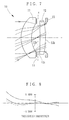
- a taking lens 10, as shown in Fig. 1, comprises a first meniscus lens 11 having a convex surface facing an object side and a second lens 12 having a positive power, arranged in this order from the object side. Between the first and second lenses 11 and 12, a flare stop 13 is positioned to prevent occurrence of flare by restricting light paths on which off-axial light rays traveling. Moreover, on the image side surface 12b of the second lens 12, a stop aperture 15 is positioned. The image side surface 11b of the first lens 11 and either surface 12a and 12b of the second lens 12 are aspherical. Note that a position as shown in a dotted line in Fig. 1, represents a position for inserting a smaller stop that controls light amount for exposure when the taking lens 10 is used with a shutter mechanism having a constant speed.
- the image side surfaces 11b and 12b of the first and second lenses 11 and 12 are aspherical.
- the radiuses of the clear apertures of the flare stop 13 and the image side surface 12b of the second lens 12 are constructed to be equal to the height of an axial light bundle.
- the photo film positioned at an image surface is curved to a radius of curvature R (-100) along its longitudinal direction.
- Table 1 shows the lens data of the taking lens 10.
- i represents the surface serial number of the respective surfaces of the first and second lenses 11 and 12 in the order from the object side
- R represents the radius of curvature of the respective surface
- D represents the distance between two adjacent surfaces, i.e. the thickness of the lenses or the air space between the two lenses 11 and 12 in the unit of millimeter
- N represents the index of refraction.
- the film surface positioned an image surface has a concave shape in a longitudinal direction, viewed from the object side, but the image surface is not exactly spherical. Therefore, in the following embodiments, the radius of curvature of the image surface indicates a curvature of the image surface relative to the diagonal direction.
- An asterisk * is allocated to aspherical surfaces.
- all aspherical surfaces satisfy the above definition.
- the first embodiment satisfies conditions (1) and (2): 0.25 ⁇ F/F1 ⁇ 0.39 -2.5 ⁇ F/R3 ⁇ f1 ⁇ 1.5
- the radius E1 of clear aperture of the flare stop 13 and the height of the axial bundle from the optical axis at the position of the flare stop 13 are:
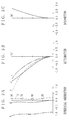
- the curves d, g and C represent spherical aberrations relative to the d-line (587.6 nm), the g-line (435.8 nm) and the C-line (656.3 nm).
- the curves S and T represent astigmatisms in the sagittal image surface and the tangential image surface respectively.
- the curve F represents astigmatism in the film surface formed spherically to a radius of curvature R.
- each of the aberrations is calculated in all embodiments in which the position of the flare stop 13 is considered the position of the stop, and the light passing through the center of the flare stop 13 is considered as a chief ray.
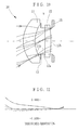
- Fig. 4 shows the lens composition of the second embodiment of the present invention. Note that in the following embodiments, portions the same as the first embodiment are shown by the same reference numbers in Fig. 1.
- the image side surface 11b and 12b of the first and second lenses 11 and 12 are aspherical like the first embodiment.
- the flare stop 13 it is to gain brighter margin of the image field that the flare stop 13 has a larger inner diameter.
- the photo film is also curved to a radius of curvature R (-100) along its longitudinal direction.
- the lens data and the aspherical coefficients of the taking lens of the second embodiment are shown in the following Tables 3 and 4.
- Fig. 7 shows the lens composition of the third embodiment of the present invention.
- the image side surface 11b and 12b of the first and second lenses 11 and 12 are aspherical as well.
- the image side surface 12b of the second lens 12 has longer clear aperture to gain more amount of light on margin of the image field.
- the photo film is also curved to a radius of curvature R (-100) along its longitudinal direction.
- the lens data and the aspherical coefficients of the taking lens of the third embodiment are shown in the following Tables 5 and 6.
- Fig. 10 shows the lens composition of the fourth embodiment of the present invention.
- the image side surface 11b and 12b of the first and second lenses 11 and 12 are aspherical as well.
- the radiuses of the clear apertures of the flare stop 13 and the image side surface 12b of the second lens 12 are designed to be equal to the height of the axial bundle.
- the photo film is also curved to a radius of curvature R (-100) along its longitudinal direction.
- the lens data and the aspherical coefficients of the taking lens of the fourth embodiment are shown in the following Tables 7 and 8.
- the flare stop 13 and the stop aperture 15 are provided respectively between the first and second lenses and on the image side surface of the second lens.
- the height of the off-axial light rays becomes lower than the height of the axial light bundle between the image side surfaces of the first and second lenses in the taking lens of the present invention, so the lens properties and the illuminance of the image surface are not defected.
- a good image can be formed in the entire image surface.
- the taking lens 10 of the fourth embodiment shown in Fig. 10 is constituted the taking lens in which the positions of the flare stop 13 and the stop aperture 15 are swapped over, whereas the radius E2 of the clear aperture on the image side surface 12b of the second lens 12 is 1.85 mm.
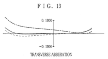
- the transverse aberration curve of the taking lens of the fifth embodiment is shown in Fig. 13.
Landscapes
- Physics & Mathematics (AREA)
- General Physics & Mathematics (AREA)
- Optics & Photonics (AREA)
- Lenses (AREA)
Abstract
Description
| i | R | D | Radius of clear aperture | Height of the axial bundle | N | Dispersion |
| 1 | 4.290 | 1.60 | 2.58 | 5.57 | 1.492 | 57.5 |
| 2 | 4.106* | 0.82 | 2.24 | 2.24 | ||
| Flare stop | ∞ | 0.17 | 2.24 | 2.24 | ||
| Smaller stop | ∞ | 0.41 | ||||
| 3 | ∞ | 0.79 | 2.24 | 2.24 | 1.492 | 57.5 |
| 4 | -20.294* | 0.15 | 2.24 | 2.24 | ||
| Stop aperture | ∞ | 28.334 | 2.21 | 2.21 | ||
| Image surface | -149.330 | -0.25 |
| i=2 | i=4 | |
| K | 0.558419 | 0.000000 |
| A | -0.111893E-04 | -0.595526E-03 |
| B | 0.000000E+00 | 0.164995E-04 |
| C | 0.000000E+00 | -0.961223E-05 |
| D | 0.000000E+00 | 0.000000E+00 |
- E2 = 2.24 mm
- H2 = 2.24 mm
- E1/H1 = 1.0
- E2/H2 = 1.0
| i | R | D | Radius of clear aperture | Height of the axial bundle | N | Dispersion |
| 1 | 4.429 | 1.70 | 2.85 | 2.58 | 1.492 | 57.5 |
| 2 | 4.273* | 0.82 | ||||
| Flare stop | ∞ | 0.17 | 2.25 | 2.23 | ||
| Smaller stop | ∞ | 0.60 | ||||
| 3 | 200.00 | 0.90 | 2.22 | 1.492 | 57.5 | |
| 4 | -23.789* | 0.15 | 2.21 | 2.21 | ||
| Stop aperture | ∞ | 28.0 | 2.19 | 2.19 | ||
| Image surface | -149.330 | -0.274 |
| i=2 | i=4 | |
| K | 0.569585 | 0.000000 |
| A | 0.308279E-04 | -0.558545E-03 |
| B | -0.251255E-04 | 0.515257E-04 |
| C | 0.000000E+00 | -0.866010E-05 |
| D | 0.000000E+00 | 0.000000E+00 |
As shown in Table 3, the characteristic values of "E1/H1" and "E2/H2" are:
| i | R | D | Radius of clear aperture | Height of the axial bundle | N | Dispersion |
| 1 | 4.513 | 1.70 | 2.77 | 2.58 | 1.492 | 57.5 |
| 2 | 4.343 * | 0.82 | ||||
| Flare stop | ∞ | 0.17 | 2.24 | 2.24 | ||
| Smaller stop | ∞ | 0.41 | ||||
| 3 | -100.900 | 0.90 | 1.492 | 57.5 | ||
| 4 | -17.197* | 0.15 | 2.26 | 2.24 | ||
| Stop aperture | ∞ | 28.316 | 2.35 | 2.22 | ||
| Image surface | -149.330 | -0.159 |
| i=2 | i=4 | |
| K | 0.569585 | 0.000000 |
| A | 0.308279E-04 | -0.558545E-03 |
| B | -0.251255E-04 | 0.515257E-04 |
| C | 0.000000E+00 | -0.866010E-05 |
| D | 0.000000E+00 | 0.000000E+00 |
As shown in Table 5, the characteristic values of "E1/H1" and "E2/H2" are:
| i | R | D | Radius of clear aperture | Height of the axial bundle | N | Dispersion |
| 1 | 4.286 | 1.70 | 2.5 | 2.06 | 1.492 | 57.5 |
| 2 | 4.100* | 0.82 | ||||
| Flare stop | ∞ | 0.17 | 1.80 | 1.80 | ||
| Smaller stop | ∞ | 0.41 | ||||
| 3 | ∞ | 0.79 | 1.492 | 57.5 | ||
| 4 | -20.511* | 0.15 | 1.78 | 1.78 | ||
| Stop aperture | ∞ | 28.316 | 1.77 | 1.77 | ||
| Image surface | -149.330 | -0.392 |
| i=2 | i=4 | |
| K | -0.66147 | 0.000000 |
| A | 0.208782E-02 | -0.574671E-03 |
| B | 0.174335E-03 | -0.150350E-04 |
| C | 0.000000E+00 | 0.000000E+00 |
| D | 0.000000E+00 | 0.000000E+00 |
Claims (10)
- A taking lens comprising a first meniscus lens (11) having a convex surface facing an object side and a second lens (12) having a positive power, wherein an image side surface (11b) of said first lens and either surface of said second lens (12) are aspherical, and wherein said taking lens satisfies the following condition:
- A taking lens as defined in claim 1 further comprising a stop (15) disposed at an image side surface (12b) of said second lens and a flare stop (13) that restricts light paths of off-axial rays disposed between said first and second lenses (11, 12), wherein said first lens (11) further satisfies the following condition:
- A taking lens as defined in claim 1 further comprising a stop (15) disposed between said first and second lenses (11, 12), wherein said taking lens satisfies the following condition:
- A taking lens as defined in claim 1 to 3 further comprising a smaller stop disposed between said first and second lenses (11, 12).
- A taking lens comprising:wherein radiuses of clear apertures of said flare stop (13) and said aspherical surface of said second lens are equal to a height of an axial bundle from the optical axis; anda first lens (11) disposed on an object side, and said first lens (11) being a meniscus lens having a convex surface on an object side and an aspherical surface on an image side (11b);a second lens (12) disposed behind said first lens (11), and said second lens (12) having a positive power and an aspherical surface on an image side (12b);a flare stop (13) disposed between said first and second lenses (11, 12);a stop (13) disposed at an image side surface of said second lens (12);
wherein said taking lens satisfies the following condition: - A taking lens as defined in claim 5 further satisfying the following condition:
- A taking lens as defined in claim 6 further satisfying the following condition:
- A taking lens as defined in claim 7, wherein a radius of a clear aperture of said flare stop (13) is 2.25 mm.
- A taking lens as defined in claim 7, wherein a radius of a clear aperture of an image side surface (12b) of said second lens is 2.26 mm.
- A taking lens comprising:wherein radiuses of clear apertures of said flare stop (15) and said aspherical surface of said second lens (12) are equal to a height of an axial bundle from the optical axis; anda first lens (11) disposed on an object side, and said first lens (11) being a meniscus lens having a convex surface on an object side and an aspherical surface on an image side;a second lens (12) disposed behind said first lens (11), and said second lens (12) having a positive power and an aspherical surface on an image side (12b);a stop (13) disposed between said first and second lenses (11, 12);a flare stop (15) disposed at an image side surface (12a) of said second lens;
wherein said taking lens (10) satisfies the following condition:
Applications Claiming Priority (2)
| Application Number | Priority Date | Filing Date | Title |
|---|---|---|---|
| JP2000205269A JP2002023050A (en) | 2000-07-06 | 2000-07-06 | Photographing lens |
| JP2000205269 | 2000-07-06 |
Publications (3)
| Publication Number | Publication Date |
|---|---|
| EP1170617A2 true EP1170617A2 (en) | 2002-01-09 |
| EP1170617A3 EP1170617A3 (en) | 2004-04-07 |
| EP1170617B1 EP1170617B1 (en) | 2006-08-09 |
Family
ID=18702389
Family Applications (1)
| Application Number | Title | Priority Date | Filing Date |
|---|---|---|---|
| EP01305513A Expired - Lifetime EP1170617B1 (en) | 2000-07-06 | 2001-06-26 | Objective with two aspherical lenses |
Country Status (4)
| Country | Link |
|---|---|
| US (1) | US6628463B2 (en) |
| EP (1) | EP1170617B1 (en) |
| JP (1) | JP2002023050A (en) |
| DE (1) | DE60122062T2 (en) |
Cited By (1)
| Publication number | Priority date | Publication date | Assignee | Title |
|---|---|---|---|---|
| EP1335227A3 (en) * | 2002-02-07 | 2005-01-12 | Enplas Corporation | Image pickup lens |
Families Citing this family (12)
| Publication number | Priority date | Publication date | Assignee | Title |
|---|---|---|---|---|
| JP4217415B2 (en) * | 2001-04-04 | 2009-02-04 | オリンパス株式会社 | Electronic imaging device |
| JP4508521B2 (en) * | 2002-07-16 | 2010-07-21 | オリンパス株式会社 | Imaging device |
| JP3717486B2 (en) * | 2003-03-10 | 2005-11-16 | フジノン株式会社 | Imaging lens |
| JP2005062282A (en) | 2003-08-20 | 2005-03-10 | Fuji Photo Film Co Ltd | Photographic lens |
| JP4861797B2 (en) | 2006-11-21 | 2012-01-25 | 株式会社エンプラス | Imaging lens and imaging apparatus provided with the same |
| TW201227036A (en) * | 2010-12-30 | 2012-07-01 | E Pin Optical Industry Co Ltd | Reading optical lens module |
| US8848299B2 (en) | 2011-01-24 | 2014-09-30 | AO Ether Corporation | Two lens module including a plano-convex lens |
| JP5949438B2 (en) * | 2012-10-23 | 2016-07-06 | 株式会社ニコン | Optical system and optical apparatus having the same |
| DE102013206394A1 (en) * | 2013-04-11 | 2014-10-16 | Asphericon Gmbh | Refractive beam shaper |
| CN113009675B (en) * | 2021-03-24 | 2022-05-13 | 天津欧菲光电有限公司 | Optical system, image capturing module and electronic equipment |
| CN115390222B (en) * | 2022-08-31 | 2024-06-07 | 东莞晶彩光学有限公司 | Two-piece type short-focus optical lens |
| CN119535723B (en) * | 2024-11-08 | 2025-10-28 | 厦门力鼎光电股份有限公司 | Code scanning lens with wide working object distance and equipment thereof |
Family Cites Families (11)
| Publication number | Priority date | Publication date | Assignee | Title |
|---|---|---|---|---|
| JPH01307712A (en) | 1988-06-06 | 1989-12-12 | Konica Corp | Photographic lens |
| US6031670A (en) * | 1990-08-28 | 2000-02-29 | Sankyo Seiki Mfg. Co., Ltd. | Wide-angle lens |
| JP3203566B2 (en) | 1992-04-02 | 2001-08-27 | コニカ株式会社 | Wide-angle lens |
| JPH07333494A (en) | 1994-06-06 | 1995-12-22 | Konica Corp | Photographing lens |
| JP3444453B2 (en) * | 1995-04-04 | 2003-09-08 | 富士写真光機株式会社 | Wide angle lens for camera |
| US5739965A (en) * | 1995-05-31 | 1998-04-14 | Fuji Photo Optical Co., Ltd. | Wide angle lens system for camera |
| JP3531023B2 (en) * | 1996-06-12 | 2004-05-24 | コニカミノルタホールディングス株式会社 | Photography lens and camera |
| JP2848523B2 (en) * | 1996-09-27 | 1999-01-20 | 株式会社日出 | Imaging lens |
| JP4057140B2 (en) * | 1998-04-14 | 2008-03-05 | フジノン株式会社 | Imaging lens |
| JP2000227547A (en) * | 1999-02-05 | 2000-08-15 | Fuji Photo Film Co Ltd | Photographic lens and camera using the same |
| JP3393186B2 (en) * | 1999-12-22 | 2003-04-07 | マイルストーン株式会社 | Imaging lens |
-
2000
- 2000-07-06 JP JP2000205269A patent/JP2002023050A/en active Pending
-
2001
- 2001-06-26 EP EP01305513A patent/EP1170617B1/en not_active Expired - Lifetime
- 2001-06-26 DE DE60122062T patent/DE60122062T2/en not_active Expired - Fee Related
- 2001-07-05 US US09/897,884 patent/US6628463B2/en not_active Expired - Fee Related
Cited By (2)
| Publication number | Priority date | Publication date | Assignee | Title |
|---|---|---|---|---|
| EP1335227A3 (en) * | 2002-02-07 | 2005-01-12 | Enplas Corporation | Image pickup lens |
| US7139134B2 (en) | 2002-02-07 | 2006-11-21 | Enplas Corporation | Image pickup lens |
Also Published As
| Publication number | Publication date |
|---|---|
| DE60122062D1 (en) | 2006-09-21 |
| US6628463B2 (en) | 2003-09-30 |
| EP1170617A3 (en) | 2004-04-07 |
| EP1170617B1 (en) | 2006-08-09 |
| DE60122062T2 (en) | 2007-08-16 |
| US20020015238A1 (en) | 2002-02-07 |
| JP2002023050A (en) | 2002-01-23 |
Similar Documents
| Publication | Publication Date | Title |
|---|---|---|
| US7777974B2 (en) | Macro lens, optical apparatus, and method for manufacturing the macro lens | |
| JP3769373B2 (en) | Bright wide-angle lens | |
| JP2000227547A (en) | Photographic lens and camera using the same | |
| JP4776796B2 (en) | Zoom lens and optical apparatus using the same | |
| JP3725284B2 (en) | Compact wide-angle lens | |
| US6628463B2 (en) | Taking lens | |
| US6844987B2 (en) | Zoom lens system for covering superwide-angle area | |
| JP3925748B2 (en) | Small lens | |
| JP2003149545A (en) | Front-shutter type single focal point lens | |
| US7075733B2 (en) | Zoom lens system and image pickup apparatus including the same | |
| CN115104055B (en) | Optical systems and optical equipment | |
| JP6938845B2 (en) | Optical system and optical equipment | |
| JP4624581B2 (en) | Inner focus lens | |
| JP3454992B2 (en) | Viewfinder optical system | |
| JP2002350720A (en) | Single focus lens | |
| JPH1172720A (en) | Relay type real image finder optical system | |
| US7436601B2 (en) | Two-group zoom lens and an electronic imaging apparatus having it | |
| JP2001337266A (en) | Photographing lens and camera using the same | |
| JP3713335B2 (en) | Wide angle lens | |
| JP3231404B2 (en) | Shooting lens | |
| US7041958B2 (en) | Lens system and image-taking apparatus having the same | |
| JPH05281465A (en) | Wide-angle lens | |
| JP3588518B2 (en) | Close-up lens | |
| JP3681132B2 (en) | Zoom finder | |
| JP2000266997A (en) | Photographing lens and camera using same |
Legal Events
| Date | Code | Title | Description |
|---|---|---|---|
| PUAI | Public reference made under article 153(3) epc to a published international application that has entered the european phase |
Free format text: ORIGINAL CODE: 0009012 |
|
| AK | Designated contracting states |
Kind code of ref document: A2 Designated state(s): AT BE CH CY DE DK ES FI FR GB GR IE IT LI LU MC NL PT SE TR |
|
| AX | Request for extension of the european patent |
Free format text: AL;LT;LV;MK;RO;SI |
|
| PUAL | Search report despatched |
Free format text: ORIGINAL CODE: 0009013 |
|
| AK | Designated contracting states |
Kind code of ref document: A3 Designated state(s): AT BE CH CY DE DK ES FI FR GB GR IE IT LI LU MC NL PT SE TR |
|
| AX | Request for extension of the european patent |
Extension state: AL LT LV MK RO SI |
|
| RIC1 | Information provided on ipc code assigned before grant |
Ipc: 7G 02B 9/06 B Ipc: 7G 02B 9/04 B Ipc: 7G 02B 13/18 A |
|
| 17P | Request for examination filed |
Effective date: 20041004 |
|
| AKX | Designation fees paid |
Designated state(s): DE FR GB |
|
| 17Q | First examination report despatched |
Effective date: 20041201 |
|
| GRAP | Despatch of communication of intention to grant a patent |
Free format text: ORIGINAL CODE: EPIDOSNIGR1 |
|
| GRAS | Grant fee paid |
Free format text: ORIGINAL CODE: EPIDOSNIGR3 |
|
| GRAA | (expected) grant |
Free format text: ORIGINAL CODE: 0009210 |
|
| AK | Designated contracting states |
Kind code of ref document: B1 Designated state(s): DE FR GB |
|
| REG | Reference to a national code |
Ref country code: GB Ref legal event code: FG4D |
|
| REF | Corresponds to: |
Ref document number: 60122062 Country of ref document: DE Date of ref document: 20060921 Kind code of ref document: P |
|
| ET | Fr: translation filed | ||
| RAP2 | Party data changed (patent owner data changed or rights of a patent transferred) |
Owner name: FUJIFILM CORPORATION |
|
| PLBE | No opposition filed within time limit |
Free format text: ORIGINAL CODE: 0009261 |
|
| STAA | Information on the status of an ep patent application or granted ep patent |
Free format text: STATUS: NO OPPOSITION FILED WITHIN TIME LIMIT |
|
| 26N | No opposition filed |
Effective date: 20070510 |
|
| REG | Reference to a national code |
Ref country code: FR Ref legal event code: TP Ref country code: FR Ref legal event code: CD |
|
| PGFP | Annual fee paid to national office [announced via postgrant information from national office to epo] |
Ref country code: DE Payment date: 20080703 Year of fee payment: 8 |
|
| PGFP | Annual fee paid to national office [announced via postgrant information from national office to epo] |
Ref country code: FR Payment date: 20080617 Year of fee payment: 8 |
|
| PGFP | Annual fee paid to national office [announced via postgrant information from national office to epo] |
Ref country code: GB Payment date: 20080702 Year of fee payment: 8 |
|
| GBPC | Gb: european patent ceased through non-payment of renewal fee |
Effective date: 20090626 |
|
| REG | Reference to a national code |
Ref country code: FR Ref legal event code: ST Effective date: 20100226 |
|
| PG25 | Lapsed in a contracting state [announced via postgrant information from national office to epo] |
Ref country code: FR Free format text: LAPSE BECAUSE OF NON-PAYMENT OF DUE FEES Effective date: 20090630 |
|
| PG25 | Lapsed in a contracting state [announced via postgrant information from national office to epo] |
Ref country code: GB Free format text: LAPSE BECAUSE OF NON-PAYMENT OF DUE FEES Effective date: 20090626 |
|
| PG25 | Lapsed in a contracting state [announced via postgrant information from national office to epo] |
Ref country code: DE Free format text: LAPSE BECAUSE OF NON-PAYMENT OF DUE FEES Effective date: 20100101 |