EP1170563A2 - Refrigerated cabinet, in particular refrigerator or freezer - Google Patents
Refrigerated cabinet, in particular refrigerator or freezer Download PDFInfo
- Publication number
- EP1170563A2 EP1170563A2 EP01108669A EP01108669A EP1170563A2 EP 1170563 A2 EP1170563 A2 EP 1170563A2 EP 01108669 A EP01108669 A EP 01108669A EP 01108669 A EP01108669 A EP 01108669A EP 1170563 A2 EP1170563 A2 EP 1170563A2
- Authority
- EP
- European Patent Office
- Prior art keywords
- seal
- door
- cabinet according
- refrigerated
- refrigerated cabinet
- Prior art date
- Legal status (The legal status is an assumption and is not a legal conclusion. Google has not performed a legal analysis and makes no representation as to the accuracy of the status listed.)
- Granted
Links
Images

Classifications
-
- F—MECHANICAL ENGINEERING; LIGHTING; HEATING; WEAPONS; BLASTING
- F25—REFRIGERATION OR COOLING; COMBINED HEATING AND REFRIGERATION SYSTEMS; HEAT PUMP SYSTEMS; MANUFACTURE OR STORAGE OF ICE; LIQUEFACTION SOLIDIFICATION OF GASES
- F25D—REFRIGERATORS; COLD ROOMS; ICE-BOXES; COOLING OR FREEZING APPARATUS NOT OTHERWISE PROVIDED FOR
- F25D23/00—General constructional features
- F25D23/08—Parts formed wholly or mainly of plastics materials
- F25D23/082—Strips
- F25D23/087—Sealing strips
Definitions
- the invention relates to a refrigerator, in particular a refrigerator or Freezer, with one between the opposite end faces the sealing frame of the refrigerated goods container and the side hinged to it Door arranged circumferential seal, comprising a plastic profile.
- the seal which is preferably attached to the door, on a contact surface of the Sealing frame of the refrigerated goods container strikes at an angle of Is inclined at 90 ° to the outer surface of the refrigerated goods container.
- the refrigerated goods container is preferably made from an inner container polymeric material and an outer container made of painted sheet metal are crimped accordingly in the edge area to accommodate the inner container. For the most part there is an insulation layer between the two components made of foamed PUR.
- the door of the refrigerator is made in a comparable way, also with an inner door Made of preferably polymeric material, an outer door made of mostly painted sheet metal and insulation, preferably in the form of foamed PUR.
- the hermetic seal of the gap between the door and the container becomes modern refrigerators and freezers with all-round, too rectangular sealing frames welded sealing profiles achieved with magnetic tapes in intended hollow chambers are equipped and mostly bellows-like Have walls to compensate for different sealing joint dimensions.
- the invention is therefore based on the object of a refrigerator of the type mentioned Kind in such a way that the sealing gap differences to be compensated also taking into account strong temperature differences between indoor and the outside space are smaller, thus reducing the seal play of the seal can be.
- the invention provides that the contact sealing surface, against which the seal rests - in the preferred case on the sealing frame of the refrigerated goods container - at an angle ⁇ ⁇ 90 ° to the outer surface of the refrigerated goods container is inclined, where appropriate in this inclined contact sealing surface a flat, the seal receiving groove can be molded.
- the seal can of course also be glued or screwed on could, is preferably the mounting surface for the seal on the door or the Refrigerated goods container with at least one circumferential, one clamp fastening leg of the seal receiving groove, if necessary also two parallel grooves are provided for two clamping leg of the seal be, the clamp fastening leg in the simplest case a fir tree profile may have, which also takes into account manufacturing tolerances a secure clamp bracket is guaranteed.
- the grooves in the corners of the sealing frame are intended in an embodiment of the invention rounded and the seal through a weld to a sealing ring be connected, what compared to the standard version angularly formed in the corners saves three welds, which is quite expensive in terms of cost Beat book.
- the design and inclination of the contact sealing surface according to the invention is special intended for refrigerated cabinets, where the refrigerated goods container and the door consist of a non-magnetic, in particular polymeric material, the Seal in this case must necessarily be a compression seal.
- the door of such a refrigerator can be locked in any manner is not the subject of the present application and should therefore also are not described in detail.
- the inclination of the system sealing surface according to the invention thus has a double advantage, namely the possibility of retracting the seal, although it is thicker is as the sealing gap, and on the other hand reducing the necessary Oversizing the compression seal diameter due to the Door deflections.
- the seal for such Refrigerating cabinet consisting of a polymeric material has at least one hollow chamber contain, in which, if necessary, an additional filling, in particular Foam filling or other materials with sufficient resilience can be introduced, wherein the seal made of one or more polymeric Materials with preferably different hardness can be made.
- an absolutely play-free hinge is included with the help of the hinges that can be used for such refrigeration units for reasons of cost possible - can finally be provided in a further development of the invention that the seal, at least on the opening side opposite the hinge the door, is provided with a reinforced profile approach.
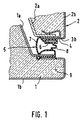
- Fig. 1 shows the previously common design of sealing a door to the container a refrigerator, both the door 1 and the refrigerated goods container 2 double-skin from a plastic inner door 1a or a plastic inner container 2a and an outer door 1b or an outer container 2b made of painted sheet metal are built up, which are preferably foamed with foamed polyurethane or the like and are therefore very well insulated.
- the edge 3b of the outer housing is bent over 90 ° over the inner housing and thus forms the system sealing surface at the same time 4, on which the seal 5 rests, with a in a pocket inserted magnetic bar 6 is provided.
- FIG. 2 is one corresponding to FIG. 1 Section through a refrigerator according to the invention, in which both the refrigerated goods container 2, as well as the door 1 made of one or more non-magnetic, in particular polymeric materials.
- a magnetic seal can of course not be used and one requires a compression seal, different in FIGS. 4 to 6 trained compression seals 5 'to 5' '' are shown.
- Crucial for the structure according to the invention is independent of whether as in FIG. 2 the seal 5 ', 5 ", 5' '' is attached to the door 1, or as in Fig.
- the inclination of the contact sealing surface 10 also has the advantage that the seal, whose diameter is definitely larger than that Sealing joint, not at the edge of the sealing frame with a 90 ° inclination of the contact sealing surface as with the prior art and trigger the closing movement can hinder. At the same time, this would not only damage the seal, there would even be a risk of being pulled out completely the seal from its holder on the door.
- FIGS. 10 to 12 show round cord seals with hollow chambers 11 and 12, respectively in the case of the seal 5 '' 'in Fig. 6, the hollow chamber 11 with a foam 13 is filled out. Basically, this applies to all of these seals - this also applies to the Seals according to FIGS. 10 to 12 - that they are made of one or more polymeric Materials with preferably different hardnesses can be produced, the hollow chambers open or filled with foam inserts could be.
- FIG. 7 and 8 show the corner formation of the refrigerator part 1 and 2, in which the groove 15 for the seal is formed, namely that in FIG. 7 is the conventional one Common case shown, in which the seal forms a rectangular frame while 8 shows the preferred case according to the invention, in which the groove in the corners are rounded so that the seal is only in one place at a time Sealing ring needs to be welded together while at the angular one Training four strips at the four corners need to be welded. This three additional welding processes make the design of the seal more expensive considerably.
- the seal 5 is on the one hand with two Clamping attachment legs 14 for engaging two corresponding parallel ones spaced grooves 15 and on the other hand has an additional profile approach 18, which is specifically on the side of the hinge remote from the Door (left in Fig. 13) between the door and the sealing frame of the refrigerated goods container jammed and thus prevents the loaded door from lowering.
- 11 and 12 show modifications of the sealing profile according to FIG. 10 with a division in several hollow chambers 12 on the one hand or with a training in which in the Hollow chamber 11 a foam cord 13 'is drawn.
- the invention has Inclination of the system sealing surface also has the advantage that the Basically not similar to a round compression seal must run in over the inner edge of the sealing frame of the counterpart, which creates a significant risk of damage or destruction or tearing the seal out.
Abstract
Description
Die Erfindung bezieht sich auf ein Kühlmöbel, insbesondere Kühlschrank oder Gefrierschrank, mit einer zwischen den einander gegenüberliegenden Stirnflächen der Dichtungsrahmen des Kühlgutbehälters und der daran seitlich anscharnierten Tür angeordneten umlaufenden, ein Kunststoffprofil umfassenden, Dichtung.The invention relates to a refrigerator, in particular a refrigerator or Freezer, with one between the opposite end faces the sealing frame of the refrigerated goods container and the side hinged to it Door arranged circumferential seal, comprising a plastic profile.
Bei der Abdichtung der Tür zum Kühlgutbehälter ist es Stand der Technik, dass die Dichtung, die bevorzugt an der Tür befestigt ist, an einer Anlagefläche des Dichtungsrahmens des Kühlgutbehälters anschlägt, die unter einem Winkel von 90° zur Kühlgutbehälteraußenfläche geneigt ist.When sealing the door to the refrigerated goods container, it is state of the art that the seal, which is preferably attached to the door, on a contact surface of the Sealing frame of the refrigerated goods container strikes at an angle of Is inclined at 90 ° to the outer surface of the refrigerated goods container.
Der Kühlgutbehälter ist dabei hergestellt aus einem Innenbehälter aus vorzugsweise polymerem Werkstoff und einem Außenbehälter aus lackierten Blechen, die im Randbereich entsprechend gebördelt sind, um den Innenbehälter aufzunehmen. Zwischen beiden Bauteilen befindet sich zum überwiegenden Teil eine Isolationsschicht aus geschäumten PUR.The refrigerated goods container is preferably made from an inner container polymeric material and an outer container made of painted sheet metal are crimped accordingly in the edge area to accommodate the inner container. For the most part there is an insulation layer between the two components made of foamed PUR.
Die Türe des Kühlmöbels ist vergleichbar hergestellt, ebenfalls mit einer Innentür aus vorzugsweise polymerem Werkstoff, einer Außentür aus meist lackierten Blechen und einer vorzugsweise als geschäumtes PUR ausgebildeten Isolierung.The door of the refrigerator is made in a comparable way, also with an inner door Made of preferably polymeric material, an outer door made of mostly painted sheet metal and insulation, preferably in the form of foamed PUR.
Die hermetische Abdichtung des Spaltes zwischen Türe und Behälter wird bei modernen Kühl- und Gefrierschränken mit umlaufenden, zu rechteckigen Dichtungsrahmen verschweißten Dichtungsprofilen erzielt, die mit Magnetbändern in dafür vorgesehenen Hohlkammern bestückt sind und meist faltenbalgähnliche Wände zum Ausgleich unterschiedlicher Dichtfugenabmessungen aufweisen.The hermetic seal of the gap between the door and the container becomes modern refrigerators and freezers with all-round, too rectangular sealing frames welded sealing profiles achieved with magnetic tapes in intended hollow chambers are equipped and mostly bellows-like Have walls to compensate for different sealing joint dimensions.
Infolge der hohen Temperaturdifferenzen zwischen dem Innenraum eines Kühl-und Gefrierschranks und den hohen Außentemperaturen, wobei ja auch tropische Verhältnisse von vornherein mit berücksichtigt sein müssen, ergibt sich eine Durchbiegung der Tür mittig zwischen den beiden Scharnieren von mehreren Millimetern, der zusätzlich zum normalen Dichtungsspalt von der Dichtung mit überbrückt werden muss. Bei Magnetdichtungen mit faltenbalgartigen Wänden zum Ausziehen lassen sich die aufgrund von Durchbiegungen hervorgerufenen großen Dichtungsspaltunterschiede noch einigermaßen überbrücken. Schwierigkeiten ergeben sich aber auf jeden Fall, wenn Kompressionsdichtungen verwendet werden müssen.As a result of the high temperature differences between the interior of a cooling and Freezers and the high outside temperatures, whereby also tropical Conditions must be taken into account from the outset, there is one Deflection of the door in the middle between the two hinges of several millimeters, which also bridges the seal in addition to the normal seal gap must become. For magnetic seals with bellows-like walls for The large ones caused by deflections can be pulled out Bridge the gap differences to some extent. Difficulties arise in any case if compression seals are used have to.
Der Erfindung liegt daher die Aufgabe zugrunde, ein Kühlmöbel der eingangs genannten Art so auszugestalten, dass die auszugleichenden Dichtungsspaltunterschiede auch unter Berücksichtigung starker Temperaturdifferenzen zwischen Innen- und Außenraum kleiner sind und damit das Dichtungsspiel der Dichtung verringert werden kann.The invention is therefore based on the object of a refrigerator of the type mentioned Kind in such a way that the sealing gap differences to be compensated also taking into account strong temperature differences between indoor and the outside space are smaller, thus reducing the seal play of the seal can be.
Zur Lösung dieser Aufgabe ist erfindungsgemäß vorgesehen, dass die Anlagedichtfläche, an der die Dichtung anliegt - im bevorzugten Fall am Dichtungsrahmen des Kühlgutbehälters - unter einem Winkel α < 90° zur Kühlgutbehälteraußenfläche geneigt ist, wobei in dieser geneigten Anlagedichtfläche gegebenenfalls noch eine flache, die Dichtung aufnehmende Rinne eingeformt sein kann.To achieve this object, the invention provides that the contact sealing surface, against which the seal rests - in the preferred case on the sealing frame of the refrigerated goods container - at an angle α <90 ° to the outer surface of the refrigerated goods container is inclined, where appropriate in this inclined contact sealing surface a flat, the seal receiving groove can be molded.
Durch diese Neigung der Anlagedichtfläche im Gegensatz zur bisher üblichen Anordnung unter einem 90°-Winkel zur Außenfläche ist die Auswirkung etwaiger Durchbiegungen des Dichtungsrahmens infolge der hohen Temperaturdifferenzen zwischen dem Innenraum des Kühlmöbels und der Außenumgebung nur in einem reduzierten Umfang wirksam, so dass die von der Dichtung abzufangenden Dichtspaltunterschiede geringer sind und damit die Anforderungen an die Dichtung geringer werden.Due to this inclination of the system sealing surface in contrast to the previously usual arrangement the impact is more at a 90 ° angle to the outer surface Deflection of the sealing frame due to the high temperature differences between the inside of the refrigerator and the outside only in one reduced scope effective, so that the sealing gap differences to be absorbed by the seal are lower and therefore the requirements for the seal are lower become.
Obgleich die Dichtung selbstverständlich auch angeklebt oder angeschraubt sein könnte, ist bevorzugt die Befestigungsfläche für die Dichtung an der Tür oder dem Kühlgutbehälter mit wenigstens einer umlaufenden, einen Klemmbefestigungsschenkel der Dichtung aufnehmenden Nut versehen, gegebenenfalls können auch zwei parallele Nuten für zwei Klemmbefestigungsschenkel der Dichtung vorgesehen sein, wobei der Klemmbefestigungsschenkel im einfachsten Fall ein Tannenbaumprofil aufweisen kann, das auch unter Berücksichtigung von Fertigungstoleranzen eine sichere Klemmhalterung gewährleistet.Although the seal can of course also be glued or screwed on could, is preferably the mounting surface for the seal on the door or the Refrigerated goods container with at least one circumferential, one clamp fastening leg of the seal receiving groove, if necessary also two parallel grooves are provided for two clamping leg of the seal be, the clamp fastening leg in the simplest case a fir tree profile may have, which also takes into account manufacturing tolerances a secure clamp bracket is guaranteed.
Dabei sollen in Ausgestaltung der Erfindung die Nuten in den Ecken der Dichtungsrahmen gerundet und die Dichtung durch eine Schweißnaht zu einem Dichtring verbunden sein, was gegenüber der in den Ecken eckig ausgebildeten Standardversion drei Schweißnähte einspart, die kostenmäßig doch recht erheblich zu Buch schlagen.The grooves in the corners of the sealing frame are intended in an embodiment of the invention rounded and the seal through a weld to a sealing ring be connected, what compared to the standard version angularly formed in the corners saves three welds, which is quite expensive in terms of cost Beat book.
Die erfindungsgemäße Ausbildung und Neigung der Anlagedichtfläche ist speziell für Kühlmöbel gedacht, bei denen der Kühlgutbehälter und die Tür einheitlich aus einem nichtmagnetischen, insbesondere polymeren Werkstoff bestehen, wobei die Dichtung in diesem Fall notwendigerweise eine Kompressionsdichtung sein muss. Die Zuhaltung der Tür eines solchen Kühlmöbels kann in beliebiger Weise erfolgen, ist aber nicht Gegenstand der vorliegenden Anmeldung und soll daher auch im Einzelnen nicht näher beschrieben werden.The design and inclination of the contact sealing surface according to the invention is special intended for refrigerated cabinets, where the refrigerated goods container and the door consist of a non-magnetic, in particular polymeric material, the Seal in this case must necessarily be a compression seal. The door of such a refrigerator can be locked in any manner is not the subject of the present application and should therefore also are not described in detail.
Bei einem solchen Kühlmöbel mit einer Kompressionsdichtung muss die Dichtung ja von vorneherein einen größeren Durchmesser aufweisen als die größtmögliche Abmessung der Dichtfuge. Dies wiederum hätte zur Folge, dass bei einer Anordnung der Anlagedichtfläche unter 90° zur Außenseitenwand des Kühlmöbels wie bei den herkömmlichen Konstruktionen mit Magnetdichtungen, die Dichtung beim Schließen an der Kante des Dichtrahmens hängen bleiben würde, so dass die Gefahr einer Beschädigung oder gar eines Herausreißens entstünde. Bei den vorhandenen Magnetdichtungen, bei denen die Dichtungshöhe der eingebauten Dichtung ja erheblich kleiner ist als die tatsächliche Dichtfuge, da ja erst durch das Anziehen der Magnetleiste die Dichtung in die Dichtstellung ausgefahren wird, spielt dies natürlich keine Rolle. Bei Kompressionsdichtungen würde aber die bisherige 90°-Orientierung der Anlagedichtfläche zu Funktionsproblemen führen. Die erfindungsgemäße Neigung der Anlagedichtfläche hat also einen doppelten Vorteil, nämlich einmal die Möglichkeit des Einfahrens der Dichtung, obgleich sie dicker ist als der Dichtspalt, und zum anderen die Verringerung der notwendigen Überdimensionierung des Kompressionsdichtungsdurchmessers aufgrund der Türdurchbiegungen.In such a refrigerator with a compression seal, the seal must yes, from the outset have a larger diameter than the largest possible Dimension of the sealing joint. This in turn would result in an arrangement the system sealing surface at 90 ° to the outside wall of the refrigerator, such as in conventional constructions with magnetic seals, the seal in Closing would get caught on the edge of the sealing frame, leaving the There is a risk of damage or even tearing out. With the existing ones Magnetic seals where the seal height of the built-in Sealing is considerably smaller than the actual sealing joint, because only through that Tightening the magnetic strip the seal is extended to the sealing position, of course this doesn't matter. With compression seals, however, the previous one would 90 ° orientation of the system sealing surface can lead to functional problems. The inclination of the system sealing surface according to the invention thus has a double advantage, namely the possibility of retracting the seal, although it is thicker is as the sealing gap, and on the other hand reducing the necessary Oversizing the compression seal diameter due to the Door deflections.
Gemäß einem weiteren Merkmal der Erfindung soll die Dichtung für ein solches aus einem polymeren Werkstoffen bestehendes Kühlmöbel wenigstens eine Hohlkammer enthalten, in die gegebenenfalls eine zusätzliche Füllung, insbesondere Schaumstofffüllung oder anderer Werkstoffe mit ausreichendem Rückstellvermögen eingebracht sein kann, wobei die Dichtung aus einem oder mehreren polymeren Werkstoffen mit vorzugsweise unterschiedlichen Härten gefertigt sein kann.According to a further feature of the invention, the seal for such Refrigerating cabinet consisting of a polymeric material has at least one hollow chamber contain, in which, if necessary, an additional filling, in particular Foam filling or other materials with sufficient resilience can be introduced, wherein the seal made of one or more polymeric Materials with preferably different hardness can be made.
Um ein sich Absenken der beladenen schweren Tür zu verhindern oder diesem weitestgehend entgegenzuwirken - eine absolut spielfreie Anscharnierung ist mit Hilfe der aus Kostengründen für solche Kühlmöbel einsetzbaren Scharniere nicht möglich - kann schließlich in Weiterbildung der Erfindung vorgesehen sein, dass die Dichtung, zumindest auf der dem Scharnier gegenüberliegenden Öffnungsseite der Tür, mit einem verstärkten Profilansatz versehen ist.To prevent or lower the loaded heavy door counteract as much as possible - an absolutely play-free hinge is included With the help of the hinges that can be used for such refrigeration units for reasons of cost possible - can finally be provided in a further development of the invention that the seal, at least on the opening side opposite the hinge the door, is provided with a reinforced profile approach.
Weitere Vorteile, Merkmale und Einzelheiten der Erfindung ergeben sich aus der nachfolgenden Beschreibung einiger Ausführungsbeispiele sowie anhand der Zeichnung. Dabei zeigen:
- Fig. 1
- einen Querschnitt durch eine Ecke eines Kühlmöbels auf der Anlenkseite mit einer herkömmlichen Magnetdichtung,
- Fig. 2
- einen der Fig. 1 entsprechenden Schnitt durch ein erfindungsgemäßes Kühlmöbel mit einheitlich aus einem oder mehreren nichtmagnetischen polymeren Werkstoffen bestehenden Aufbau und einer erfindungsgemäßen Dichtanordnung im Schließzustand,
- Fig. 3
- ein der Fig. 2 entsprechendes Schnittbild im teilweise geöffneten Zustand der Tür,
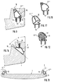
- Fig. 4 bis 6
- Schnitt durch unterschiedlich ausgebildete Dichtungen für die Kühlmöbelkonstruktion nach den Fig. 2 und 3,
- Fig. 7 und 8
- unterschiedlich ausgebildete Nutführungen in den Ecken des Kühlgutbehälters,
- Fig. 9
- eine gegenüber dem Schnitt nach Fig. 2 abgewandelte Ausbildung der Dichtung mit einem zusätzlich ein Absenken der Tür verhindernden Profilansatz,
- Fig. 10 bis 12
- Schnitt durch unterschiedlich ausgebildete Dichtungen für die Konstruktion nach Fig. 9,
- Fig. 13
- einen Schnitt durch die Tür eines Kühlmöbels mit einer Dichtung gemäß Fig. 9, und
- Fig. 14
- einen den Fig. 2 und 9 entsprechenden Schnitt durch ein erfindungsgemäßes Kühlmöbel, wobei die Dichtung am Kühlgutbehälter befestigt und die Anlagedichtfläche an der Tür ausgebildet ist.
- Fig. 1
- 2 shows a cross section through a corner of a refrigerator on the articulation side with a conventional magnetic seal,
- Fig. 2
- 1 shows a section corresponding to FIG. 1 through a refrigerator according to the invention with a structure consisting uniformly of one or more non-magnetic polymeric materials and a sealing arrangement according to the invention in the closed state,
- Fig. 3
- 2 corresponding sectional view in the partially open state of the door,
- 4 to 6
- Section through differently designed seals for the refrigerator construction according to FIGS. 2 and 3,
- 7 and 8
- differently designed groove guides in the corners of the refrigerated goods container,
- Fig. 9
- a design of the seal which is modified compared to the section according to FIG. 2, with a profile shoulder which additionally prevents the door from being lowered,
- 10 to 12
- Section through differently designed seals for the construction according to FIG. 9,
- Fig. 13
- a section through the door of a refrigerator with a seal according to FIG. 9, and
- Fig. 14
- a section corresponding to FIGS. 2 and 9 through a refrigerator according to the invention, wherein the seal is attached to the refrigerated goods container and the contact sealing surface is formed on the door.
Die Fig. 1 zeigt die bislang gängige Ausbildung der Abdichtung einer Tür zum Behälter
eines Kühlmöbels, wobei sowohl die Tür 1 als auch der Kühlgutbehälter 2
zweischalig aus einer Kunststoffinnentür 1a bzw. einem Kunststoffinnenbehälter
2a und einer Außentür 1b bzw. einem Außenbehälter 2b aus lackiertem Blech
aufgebaut sind, die vorzugsweise mit geschäumten Polyurethan od. dgl. ausgeschäumt
und damit sehr gut isoliert sind. Der Umbug 3b des Außengehäuses ist
um 90° über das Innengehäuse umgebogen und bildet damit gleichzeitig die Anlagedichtfläche
4, an welcher die Dichtung 5 anliegt, die mit einer in eine Tasche
eingelegten Magnetleiste 6 versehen ist. Während die Dichtung in der gezeigten
Weise zwischen Innentür 1a und Außentür 1b verklemmt und damit an der Tür
gehaltert ist, liegt sie unabhängig von der jeweiligen Breite des Dichtungsspaltes
zwischen der Tür und dem Kühlgutbehälter stets am Umbug 3b an, da die faltenbalgartigen
Wände 7 und 8 eine entsprechend große Veränderungen der Dichtspaltbreite
ermöglichen. Bei 9 ist die Lage der Drehachse zum Aufschwenken der
Tür 1 angedeutet.Fig. 1 shows the previously common design of sealing a door to the container
a refrigerator, both the
Bei dem Ausführungsbeispiel nach Fig. 2 handelt es sich um einen der Fig. 1 entsprechenden
Schnitt durch ein erfindungsgemäßes Kühlmöbel, bei welchem sowohl
der Kühlgutbehälter 2, als auch die Tür 1 aus einem oder mehreren nichtmagnetischen,
insbesondere polymeren Werkstoffen bestehen. In diesem Fall
kann selbstverständlich eine Magnetdichtung nicht verwendet werden und man
benötigt eine Kompressionsdichtung, wobei in den Fig. 4 bis 6 unterschiedlich
ausgebildete Kompressionsdichtungen 5' bis 5''' dargestellt sind. Entscheidend für
den erfindungsgemäßen Aufbau ist dabei - unabhängig davon, ob wie bei Fig. 2
die Dichtung 5', 5", 5''' an der Tür 1 befestigt ist, oder wie bei Fig. 14 am Kühlgutbehälter
- dass die Anlagedichtfläche am jeweils anderen Bauteil, also die Anlagedichtfläche
10 des Dichtungsrahmens des Kühlkörpers oder die Anlagedichtfläche
10 der Tür 1 in Fig. 14 unter einem Winkel < 90° geneigt ist. Dies hat bei der
gezeigten 45° Grad-Neigung zur Folge, dass eine Durchbiegung der Türe um beispielsweise
4 mm, die in der Praxis bei den hohen Temperaturunterschieden zwischen
Innenraum und Außenraum sehr häufig auftritt und von der Dichtung abgefangen
werden muss, im Hinblick auf den Dichtungsspalt sich nur in einem Ausmaß
von etwa 2,5 mm auswirkt ― abhängig von Winkel α - so dass die Anforderungen
an die Überdimensionierung der Dichtung bezogen auf die Dichtfuge reduziert
werden können. Durch die erfindungsgemäße Schrägstellung der Anlagedichtfläche
werden im Betrieb auftretende Verbiegungen der Tür nur zu einem
Bruchteil im Dichtspalt wirksam und können somit sehr viel leichter über die Dichtung
abgefangen werden.The embodiment according to FIG. 2 is one corresponding to FIG. 1
Section through a refrigerator according to the invention, in which both
the
Neben dieser Verringerung der notwendigen Überdimensionierung der Dichtung
bezogen auf die Abmessung der Dichtfuge zum Ausgleich der Türdurchbiegung
hat die erfindungsgemäße Neigung der Anlagedichtfläche 10 auch noch den Vorteil,
dass die Dichtung, deren Durchmesser ja auf jeden Fall größer ist als die
Dichtfuge, nicht an der Kante des Dichtrahmens mit einer 90°-Neigung der Anlagedichtfläche
wie beim Stand der Technik anstoßen und dabei die Schließbewegung
behindern kann. Gleichzeitig würde dadurch nicht nur die Dichtung beschädigt,
sondern es bestünde darüber hinaus sogar die Gefahr eines völligen Herausreißens
der Dichtung aus ihrer Halterung an der Tür.In addition to this reduction in the necessary oversizing of the seal
based on the dimension of the sealing joint to compensate for door deflection
the inclination of the
Die Fig. 4 bis 6 zeigen Rundschnurdichtungen mit Hohlkammern 11 bzw. 12, wobei
im Fall der Dichtung 5''' in Fig. 6 die Hohlkammer 11 mit einem Schaumstoff
13 ausgefüllt ist. Grundsätzlich gilt für alle diese Dichtungen - dies gilt auch für die
Dichtungen gemäß den Fig. 10 bis 12 - dass sie aus einem oder mehreren polymeren
Werkstoffen mit vorzugsweise unterschiedlichen Härten gefertigt sein können,
wobei die Hohlkammern offen oder durch Schaumstoffeinlagen ausgefüllt
sein können.4 to 6 show round cord seals with
In den gezeigten Ausführungsbeispielen ist grundsätzlich eine Ausbildung der
Dichtungen gezeigt, bei denen sie mit Hilfe eines als Tannenbaumprofil ausgebildeten
Klemmbefestigungsschenkel 14 in eine Nut 15 der Befestigungsfläche 16
bzw. 17 der Tür 1 bzw. des Kühlgutbehälters 2 gehaltert sind. Selbstverständlich
wäre auch ein Ankleben einer Dichtung ohne solche Klemmbefestigungsschenkel
oder auch ein Anschrauben der Dichtung möglich. Die Einsprenghalterung mit einem
Klemmbefestigungsschenkel hat sich jedoch für die meisten Ausführungsformen
als bevorzugt erwiesen, so dass auch nur diese in den Zeichnungen dargestellt
ist.In the exemplary embodiments shown there is basically an embodiment of the
Seals shown, in which they are designed using a fir tree profile
Die Fig. 7 und 8 zeigen die Eckenausbildung des Kühlmöbelteils 1 und 2, in dem
die Nut 15 für die Dichtung angeformt ist, und zwar ist in Fig. 7 der herkömmliche
gängige Fall gezeigt, bei dem die Dichtung einen Rechteckrahmen bildet, während
in Fig. 8 der erfindungsgemäß bevorzugte Fall dargestellt ist, bei dem die Nut in
den Ecken abgerundet ist, so dass die Dichtung nur an einer Stelle zu einem
Dichtring zusammengeschweißt zu werden braucht, während bei der eckigen
Ausbildung vier Leisten an den vier Ecken verschweißt werden müssen. Diese
drei zusätzlichen Schweißvorgänge verteuern die Ausbildung der Dichtung ganz
erheblich. 7 and 8 show the corner formation of the
Bei der Ausführungsform nach Fig. 9 ist die Dichtung 5"" zum einen mit zwei
Klemmbefestigungsschenkeln 14 zum Eingreifen in entsprechend zwei parallele
beabstandete Nuten 15 versehen und weist zum anderen einen zusätzlichen Profilansatz
18 auf, der sich speziell auf der dem Scharnier abgelegenen Seite der
Tür (in Fig. 13 links) zwischen Tür und Dichtungsrahmen des Kühlgutbehälters
verklemmt und somit ein Absenken der beladenen Tür verhindert. Die Fig. 11 und
12 zeigen Abwandlungen des Dichtungsprofils gemäß Fig. 10 mit einer Aufteilung
in mehrere Hohlkammern 12 einerseits bzw. mit einer Ausbildung, bei der in die
Hohlkammer 11 eine Schaumstoffschnur 13' eingezogen ist.In the embodiment according to FIG. 9, the
Neben den geringeren Anforderungen an die Kompressibilität der Dichtung, insbesondere an das Ausmaß des zu überbrückenden Dichtungsspiels, hat die erfindungsgemäße Schrägneigung der Anlagedichtfläche auch den Vorteil, dass die im Grundsatz ähnlich wie eine Rundschnur ausgebildete Kompressionsdichtung nicht über die Innenkante des Dichtungsrahmens des Gegenbauteils einlaufen muss, wodurch sich eine erhebliche Gefahr einer Beschädigung oder Zerstörung oder eines Herausreißens der Dichtung ergeben würde.In addition to the lower demands on the compressibility of the seal, in particular to the extent of the sealing play to be bridged, the invention has Inclination of the system sealing surface also has the advantage that the Basically not similar to a round compression seal must run in over the inner edge of the sealing frame of the counterpart, which creates a significant risk of damage or destruction or tearing the seal out.
Claims (11)
Applications Claiming Priority (2)
| Application Number | Priority Date | Filing Date | Title |
|---|---|---|---|
| DE10032457A DE10032457A1 (en) | 2000-07-04 | 2000-07-04 | Refrigerated furniture, in particular a refrigerator or freezer |
| DE10032457 | 2000-07-04 |
Publications (3)
| Publication Number | Publication Date |
|---|---|
| EP1170563A2 true EP1170563A2 (en) | 2002-01-09 |
| EP1170563A3 EP1170563A3 (en) | 2002-07-17 |
| EP1170563B1 EP1170563B1 (en) | 2006-07-26 |
Family
ID=7647739
Family Applications (1)
| Application Number | Title | Priority Date | Filing Date |
|---|---|---|---|
| EP01108669A Expired - Lifetime EP1170563B1 (en) | 2000-07-04 | 2001-04-06 | Refrigerated cabinet, in particular refrigerator or freezer |
Country Status (3)
| Country | Link |
|---|---|
| EP (1) | EP1170563B1 (en) |
| AT (1) | ATE334364T1 (en) |
| DE (2) | DE10032457A1 (en) |
Cited By (1)
| Publication number | Priority date | Publication date | Assignee | Title |
|---|---|---|---|---|
| US20180259244A1 (en) * | 2017-03-10 | 2018-09-13 | Samsung Electronics Co., Ltd. | Refrigerator |
Families Citing this family (2)
| Publication number | Priority date | Publication date | Assignee | Title |
|---|---|---|---|---|
| US8490333B2 (en) | 2005-05-23 | 2013-07-23 | Electrolux Home Products, Inc. | Sealing gaskets |
| DE102006010029A1 (en) * | 2006-03-04 | 2007-09-06 | Rehau Ag + Co. | Refrigerator door has door element forming door wing, where door seal is implemented as hose seal with accurate lumen, which is held in circulating outer groove of former door element by pre-loading of both door elements |
Citations (10)
| Publication number | Priority date | Publication date | Assignee | Title |
|---|---|---|---|---|
| BE392840A (en) * | ||||
| DE685551C (en) * | 1937-11-04 | 1939-12-20 | Elektrolux Akt Ges | Refrigerator or heating cabinet |
| US2198838A (en) * | 1938-05-02 | 1940-04-30 | Philco Refrigerator Company | Refrigerator door structure |
| US2234773A (en) * | 1940-03-06 | 1941-03-11 | York Ice Machinery Corp | Seal for cold storage and like doors |
| FR1077435A (en) * | 1953-05-19 | 1954-11-08 | Watertight seal especially for closing cold rooms | |
| US2760243A (en) * | 1951-07-17 | 1956-08-28 | Jervis Corp | Method of joining materials and joint obtained thereby |
| US3023466A (en) * | 1958-04-14 | 1962-03-06 | Robert L Landis | Sealing gasket |
| US3378958A (en) * | 1966-09-21 | 1968-04-23 | Goodrich Co B F | Extrusions having integral portions of different stiffness |
| GB1318207A (en) * | 1970-03-23 | 1973-05-23 | Kenwood Mfg Woking Ltd | Cabinet for a domestic appliance |
| EP0583984A1 (en) * | 1992-08-20 | 1994-02-23 | General Electric Company | Refrigerator cabinet with combination sealing arrangement |
Family Cites Families (1)
| Publication number | Priority date | Publication date | Assignee | Title |
|---|---|---|---|---|
| SE320392B (en) * | 1967-08-02 | 1970-02-09 | Hyresgaesternas Sparkasse Och |
-
2000
- 2000-07-04 DE DE10032457A patent/DE10032457A1/en not_active Withdrawn
-
2001
- 2001-04-06 AT AT01108669T patent/ATE334364T1/en not_active IP Right Cessation
- 2001-04-06 EP EP01108669A patent/EP1170563B1/en not_active Expired - Lifetime
- 2001-04-06 DE DE50110526T patent/DE50110526D1/en not_active Expired - Fee Related
Patent Citations (10)
| Publication number | Priority date | Publication date | Assignee | Title |
|---|---|---|---|---|
| BE392840A (en) * | ||||
| DE685551C (en) * | 1937-11-04 | 1939-12-20 | Elektrolux Akt Ges | Refrigerator or heating cabinet |
| US2198838A (en) * | 1938-05-02 | 1940-04-30 | Philco Refrigerator Company | Refrigerator door structure |
| US2234773A (en) * | 1940-03-06 | 1941-03-11 | York Ice Machinery Corp | Seal for cold storage and like doors |
| US2760243A (en) * | 1951-07-17 | 1956-08-28 | Jervis Corp | Method of joining materials and joint obtained thereby |
| FR1077435A (en) * | 1953-05-19 | 1954-11-08 | Watertight seal especially for closing cold rooms | |
| US3023466A (en) * | 1958-04-14 | 1962-03-06 | Robert L Landis | Sealing gasket |
| US3378958A (en) * | 1966-09-21 | 1968-04-23 | Goodrich Co B F | Extrusions having integral portions of different stiffness |
| GB1318207A (en) * | 1970-03-23 | 1973-05-23 | Kenwood Mfg Woking Ltd | Cabinet for a domestic appliance |
| EP0583984A1 (en) * | 1992-08-20 | 1994-02-23 | General Electric Company | Refrigerator cabinet with combination sealing arrangement |
Cited By (1)
| Publication number | Priority date | Publication date | Assignee | Title |
|---|---|---|---|---|
| US20180259244A1 (en) * | 2017-03-10 | 2018-09-13 | Samsung Electronics Co., Ltd. | Refrigerator |
Also Published As
| Publication number | Publication date |
|---|---|
| ATE334364T1 (en) | 2006-08-15 |
| DE50110526D1 (en) | 2006-09-07 |
| EP1170563B1 (en) | 2006-07-26 |
| EP1170563A3 (en) | 2002-07-17 |
| DE10032457A1 (en) | 2002-01-17 |
Similar Documents
| Publication | Publication Date | Title |
|---|---|---|
| EP2872837B1 (en) | Refrigerator | |
| EP1937919B1 (en) | Furniture closure | |
| DE2911434A1 (en) | THERMAL INSULATED DOOR | |
| EP0658733B1 (en) | Refrigerator/freezer | |
| DE2415460A1 (en) | DOOR SEAL | |
| DE69807805T3 (en) | Plastic seal with deformable base for refrigerators | |
| EP3394534B1 (en) | Refrigerator and/or freezer | |
| EP0179241A2 (en) | Building panel | |
| EP1626149A2 (en) | Flat fireproof closure | |
| EP1170563B1 (en) | Refrigerated cabinet, in particular refrigerator or freezer | |
| DE102010020999A1 (en) | Complete glass door, particularly for refrigerated display cases, has two glass panes, distance holder and two rotary fitting units that are vertically or horizontally arranged to opposite-lying door-sided hinge fittings | |
| EP0062153B1 (en) | Frame-shaped plastics seal for a refrigerator door | |
| DE19907147A1 (en) | Refrigerator door has inner cladding formed out of metallic material, out of high quality steel bar in non-cutting fashion, as far as possible | |
| CH633607A5 (en) | Window with insulation glazing | |
| DE19601247A1 (en) | Extrusion for window frame and door frame | |
| AT389734B (en) | STABLE DOOR | |
| DE3513466C2 (en) | ||
| DE1601094A1 (en) | Heat-insulated freezer compartment that can be inserted in a refrigerator | |
| AT409403B (en) | WINDOWS, DOORS OR THE LIKE | |
| DE19723775C2 (en) | Room corner for a box-shaped housing | |
| DE8000006U1 (en) | FRAME TO FRAME WALL PARTS, ESPECIALLY GLAZING OR WINDOWS | |
| DE2854820A1 (en) | Swing window leaf pivot - has intermediate element between frame and leaf sections with elastic strips sealing gaps | |
| DE102004039080A1 (en) | Sealing arrangement for window or door, has seal arranged in movable sealing unit, and another seal arranged in sealing unit is provided in gap between flank and apron, where movable sealing unit seals air passage | |
| DE1196680B (en) | Cooling furniture or the like with insulation made of synthetic foam | |
| DE1451117A1 (en) | Housing for a cooling device |
Legal Events
| Date | Code | Title | Description |
|---|---|---|---|
| PUAI | Public reference made under article 153(3) epc to a published international application that has entered the european phase |
Free format text: ORIGINAL CODE: 0009012 |
|
| AK | Designated contracting states |
Kind code of ref document: A2 Designated state(s): AT BE CH CY DE DK ES FI FR GB GR IE IT LI LU MC NL PT SE TR |
|
| AX | Request for extension of the european patent |
Free format text: AL;LT;LV;MK;RO;SI |
|
| PUAL | Search report despatched |
Free format text: ORIGINAL CODE: 0009013 |
|
| AK | Designated contracting states |
Kind code of ref document: A3 Designated state(s): AT BE CH CY DE DK ES FI FR GB GR IE IT LI LU MC NL PT SE TR |
|
| AX | Request for extension of the european patent |
Free format text: AL;LT;LV;MK;RO;SI |
|
| AKX | Designation fees paid | ||
| REG | Reference to a national code |
Ref country code: DE Ref legal event code: 8566 |
|
| 17P | Request for examination filed |
Effective date: 20030324 |
|
| RBV | Designated contracting states (corrected) |
Designated state(s): AT BE CH CY DE DK ES FI FR GB GR IE IT LI LU MC NL PT SE TR |
|
| 17Q | First examination report despatched |
Effective date: 20050311 |
|
| GRAP | Despatch of communication of intention to grant a patent |
Free format text: ORIGINAL CODE: EPIDOSNIGR1 |
|
| GRAS | Grant fee paid |
Free format text: ORIGINAL CODE: EPIDOSNIGR3 |
|
| GRAA | (expected) grant |
Free format text: ORIGINAL CODE: 0009210 |
|
| AK | Designated contracting states |
Kind code of ref document: B1 Designated state(s): AT BE CH CY DE DK ES FI FR GB GR IE IT LI LU MC NL PT SE TR |
|
| PG25 | Lapsed in a contracting state [announced via postgrant information from national office to epo] |
Ref country code: IT Free format text: LAPSE BECAUSE OF FAILURE TO SUBMIT A TRANSLATION OF THE DESCRIPTION OR TO PAY THE FEE WITHIN THE PRESCRIBED TIME-LIMIT;WARNING: LAPSES OF ITALIAN PATENTS WITH EFFECTIVE DATE BEFORE 2007 MAY HAVE OCCURRED AT ANY TIME BEFORE 2007. THE CORRECT EFFECTIVE DATE MAY BE DIFFERENT FROM THE ONE RECORDED. Effective date: 20060726 Ref country code: NL Free format text: LAPSE BECAUSE OF FAILURE TO SUBMIT A TRANSLATION OF THE DESCRIPTION OR TO PAY THE FEE WITHIN THE PRESCRIBED TIME-LIMIT Effective date: 20060726 Ref country code: IE Free format text: LAPSE BECAUSE OF FAILURE TO SUBMIT A TRANSLATION OF THE DESCRIPTION OR TO PAY THE FEE WITHIN THE PRESCRIBED TIME-LIMIT Effective date: 20060726 Ref country code: GB Free format text: LAPSE BECAUSE OF FAILURE TO SUBMIT A TRANSLATION OF THE DESCRIPTION OR TO PAY THE FEE WITHIN THE PRESCRIBED TIME-LIMIT Effective date: 20060726 Ref country code: FI Free format text: LAPSE BECAUSE OF FAILURE TO SUBMIT A TRANSLATION OF THE DESCRIPTION OR TO PAY THE FEE WITHIN THE PRESCRIBED TIME-LIMIT Effective date: 20060726 |
|
| REG | Reference to a national code |
Ref country code: GB Ref legal event code: FG4D Free format text: NOT ENGLISH |
|
| REG | Reference to a national code |
Ref country code: CH Ref legal event code: EP |
|
| REG | Reference to a national code |
Ref country code: IE Ref legal event code: FG4D Free format text: LANGUAGE OF EP DOCUMENT: GERMAN |
|
| REF | Corresponds to: |
Ref document number: 50110526 Country of ref document: DE Date of ref document: 20060907 Kind code of ref document: P |
|
| REG | Reference to a national code |
Ref country code: SE Ref legal event code: TRGR |
|
| PG25 | Lapsed in a contracting state [announced via postgrant information from national office to epo] |
Ref country code: DK Free format text: LAPSE BECAUSE OF FAILURE TO SUBMIT A TRANSLATION OF THE DESCRIPTION OR TO PAY THE FEE WITHIN THE PRESCRIBED TIME-LIMIT Effective date: 20061026 |
|
| PG25 | Lapsed in a contracting state [announced via postgrant information from national office to epo] |
Ref country code: ES Free format text: LAPSE BECAUSE OF FAILURE TO SUBMIT A TRANSLATION OF THE DESCRIPTION OR TO PAY THE FEE WITHIN THE PRESCRIBED TIME-LIMIT Effective date: 20061106 |
|
| PG25 | Lapsed in a contracting state [announced via postgrant information from national office to epo] |
Ref country code: PT Free format text: LAPSE BECAUSE OF FAILURE TO SUBMIT A TRANSLATION OF THE DESCRIPTION OR TO PAY THE FEE WITHIN THE PRESCRIBED TIME-LIMIT Effective date: 20061226 |
|
| NLV1 | Nl: lapsed or annulled due to failure to fulfill the requirements of art. 29p and 29m of the patents act | ||
| GBV | Gb: ep patent (uk) treated as always having been void in accordance with gb section 77(7)/1977 [no translation filed] |
Effective date: 20060726 |
|
| REG | Reference to a national code |
Ref country code: IE Ref legal event code: FD4D |
|
| PGFP | Annual fee paid to national office [announced via postgrant information from national office to epo] |
Ref country code: SE Payment date: 20070404 Year of fee payment: 7 |
|
| PGFP | Annual fee paid to national office [announced via postgrant information from national office to epo] |
Ref country code: AT Payment date: 20070405 Year of fee payment: 7 |
|
| EN | Fr: translation not filed | ||
| PLBE | No opposition filed within time limit |
Free format text: ORIGINAL CODE: 0009261 |
|
| STAA | Information on the status of an ep patent application or granted ep patent |
Free format text: STATUS: NO OPPOSITION FILED WITHIN TIME LIMIT |
|
| 26N | No opposition filed |
Effective date: 20070427 |
|
| REG | Reference to a national code |
Ref country code: CH Ref legal event code: PL |
|
| BERE | Be: lapsed |
Owner name: REHAU A.G. + CO Effective date: 20070430 |
|
| PG25 | Lapsed in a contracting state [announced via postgrant information from national office to epo] |
Ref country code: CH Free format text: LAPSE BECAUSE OF NON-PAYMENT OF DUE FEES Effective date: 20070430 Ref country code: LI Free format text: LAPSE BECAUSE OF NON-PAYMENT OF DUE FEES Effective date: 20070430 |
|
| PG25 | Lapsed in a contracting state [announced via postgrant information from national office to epo] |
Ref country code: BE Free format text: LAPSE BECAUSE OF NON-PAYMENT OF DUE FEES Effective date: 20070430 |
|
| PG25 | Lapsed in a contracting state [announced via postgrant information from national office to epo] |
Ref country code: FR Free format text: LAPSE BECAUSE OF FAILURE TO SUBMIT A TRANSLATION OF THE DESCRIPTION OR TO PAY THE FEE WITHIN THE PRESCRIBED TIME-LIMIT Effective date: 20070511 Ref country code: GR Free format text: LAPSE BECAUSE OF FAILURE TO SUBMIT A TRANSLATION OF THE DESCRIPTION OR TO PAY THE FEE WITHIN THE PRESCRIBED TIME-LIMIT Effective date: 20061027 |
|
| PGFP | Annual fee paid to national office [announced via postgrant information from national office to epo] |
Ref country code: IT Payment date: 20080320 Year of fee payment: 8 |
|
| PG25 | Lapsed in a contracting state [announced via postgrant information from national office to epo] |
Ref country code: FR Free format text: LAPSE BECAUSE OF FAILURE TO SUBMIT A TRANSLATION OF THE DESCRIPTION OR TO PAY THE FEE WITHIN THE PRESCRIBED TIME-LIMIT Effective date: 20060726 |
|
| EUG | Se: european patent has lapsed | ||
| PG25 | Lapsed in a contracting state [announced via postgrant information from national office to epo] |
Ref country code: AT Free format text: LAPSE BECAUSE OF NON-PAYMENT OF DUE FEES Effective date: 20080406 |
|
| PG25 | Lapsed in a contracting state [announced via postgrant information from national office to epo] |
Ref country code: MC Free format text: LAPSE BECAUSE OF NON-PAYMENT OF DUE FEES Effective date: 20070430 |
|
| PG25 | Lapsed in a contracting state [announced via postgrant information from national office to epo] |
Ref country code: CY Free format text: LAPSE BECAUSE OF FAILURE TO SUBMIT A TRANSLATION OF THE DESCRIPTION OR TO PAY THE FEE WITHIN THE PRESCRIBED TIME-LIMIT Effective date: 20060726 Ref country code: LU Free format text: LAPSE BECAUSE OF NON-PAYMENT OF DUE FEES Effective date: 20070406 |
|
| PGFP | Annual fee paid to national office [announced via postgrant information from national office to epo] |
Ref country code: DE Payment date: 20090430 Year of fee payment: 9 |
|
| PG25 | Lapsed in a contracting state [announced via postgrant information from national office to epo] |
Ref country code: SE Free format text: LAPSE BECAUSE OF NON-PAYMENT OF DUE FEES Effective date: 20080407 |
|
| PG25 | Lapsed in a contracting state [announced via postgrant information from national office to epo] |
Ref country code: DE Free format text: LAPSE BECAUSE OF NON-PAYMENT OF DUE FEES Effective date: 20101103 |
|
| PG25 | Lapsed in a contracting state [announced via postgrant information from national office to epo] |
Ref country code: IT Free format text: LAPSE BECAUSE OF NON-PAYMENT OF DUE FEES Effective date: 20090406 |
|
| PG25 | Lapsed in a contracting state [announced via postgrant information from national office to epo] |
Ref country code: TR Free format text: LAPSE BECAUSE OF NON-PAYMENT OF DUE FEES Effective date: 20110727 |
|
| PGFP | Annual fee paid to national office [announced via postgrant information from national office to epo] |
Ref country code: TR Payment date: 20080314 Year of fee payment: 8 |
|
| PG25 | Lapsed in a contracting state [announced via postgrant information from national office to epo] |
Ref country code: TR Free format text: LAPSE BECAUSE OF NON-PAYMENT OF DUE FEES Effective date: 20090406 |