EP1170477A2 - Electric waterpump, fluid control valve and electric cooling fan strategy - Google Patents
Electric waterpump, fluid control valve and electric cooling fan strategy Download PDFInfo
- Publication number
- EP1170477A2 EP1170477A2 EP01116333A EP01116333A EP1170477A2 EP 1170477 A2 EP1170477 A2 EP 1170477A2 EP 01116333 A EP01116333 A EP 01116333A EP 01116333 A EP01116333 A EP 01116333A EP 1170477 A2 EP1170477 A2 EP 1170477A2
- Authority
- EP
- European Patent Office
- Prior art keywords
- engine
- electrical load
- electric
- function
- water pump
- Prior art date
- Legal status (The legal status is an assumption and is not a legal conclusion. Google has not performed a legal analysis and makes no representation as to the accuracy of the status listed.)
- Withdrawn
Links
- 238000001816 cooling Methods 0.000 title claims abstract description 36
- 239000012530 fluid Substances 0.000 title description 3
- XLYOFNOQVPJJNP-UHFFFAOYSA-N water Substances O XLYOFNOQVPJJNP-UHFFFAOYSA-N 0.000 claims abstract description 42
- 239000000446 fuel Substances 0.000 claims abstract description 23
- 238000000034 method Methods 0.000 claims abstract description 13
- 238000005086 pumping Methods 0.000 claims abstract description 9
- 239000002826 coolant Substances 0.000 claims description 52
- 230000001105 regulatory effect Effects 0.000 claims description 9
- 238000004378 air conditioning Methods 0.000 claims description 5
- 230000001276 controlling effect Effects 0.000 claims description 4
- 238000010586 diagram Methods 0.000 description 6
- 230000003247 decreasing effect Effects 0.000 description 5
- 239000007788 liquid Substances 0.000 description 5
- 238000009987 spinning Methods 0.000 description 2
- 238000013459 approach Methods 0.000 description 1
- 238000009835 boiling Methods 0.000 description 1
- 238000002485 combustion reaction Methods 0.000 description 1
- 238000012986 modification Methods 0.000 description 1
- 230000004048 modification Effects 0.000 description 1
- 238000005457 optimization Methods 0.000 description 1
- 230000000979 retarding effect Effects 0.000 description 1
- 238000010792 warming Methods 0.000 description 1
Images


Classifications
-
- F—MECHANICAL ENGINEERING; LIGHTING; HEATING; WEAPONS; BLASTING
- F01—MACHINES OR ENGINES IN GENERAL; ENGINE PLANTS IN GENERAL; STEAM ENGINES
- F01P—COOLING OF MACHINES OR ENGINES IN GENERAL; COOLING OF INTERNAL-COMBUSTION ENGINES
- F01P7/00—Controlling of coolant flow
- F01P7/14—Controlling of coolant flow the coolant being liquid
- F01P7/16—Controlling of coolant flow the coolant being liquid by thermostatic control
- F01P7/164—Controlling of coolant flow the coolant being liquid by thermostatic control by varying pump speed
-
- F—MECHANICAL ENGINEERING; LIGHTING; HEATING; WEAPONS; BLASTING
- F01—MACHINES OR ENGINES IN GENERAL; ENGINE PLANTS IN GENERAL; STEAM ENGINES
- F01P—COOLING OF MACHINES OR ENGINES IN GENERAL; COOLING OF INTERNAL-COMBUSTION ENGINES
- F01P7/00—Controlling of coolant flow
- F01P7/02—Controlling of coolant flow the coolant being cooling-air
- F01P7/04—Controlling of coolant flow the coolant being cooling-air by varying pump speed, e.g. by changing pump-drive gear ratio
- F01P7/048—Controlling of coolant flow the coolant being cooling-air by varying pump speed, e.g. by changing pump-drive gear ratio using electrical drives
-
- F—MECHANICAL ENGINEERING; LIGHTING; HEATING; WEAPONS; BLASTING
- F01—MACHINES OR ENGINES IN GENERAL; ENGINE PLANTS IN GENERAL; STEAM ENGINES
- F01P—COOLING OF MACHINES OR ENGINES IN GENERAL; COOLING OF INTERNAL-COMBUSTION ENGINES
- F01P7/00—Controlling of coolant flow
- F01P7/14—Controlling of coolant flow the coolant being liquid
- F01P7/16—Controlling of coolant flow the coolant being liquid by thermostatic control
- F01P7/167—Controlling of coolant flow the coolant being liquid by thermostatic control by adjusting the pre-set temperature according to engine parameters, e.g. engine load, engine speed
-
- F—MECHANICAL ENGINEERING; LIGHTING; HEATING; WEAPONS; BLASTING
- F01—MACHINES OR ENGINES IN GENERAL; ENGINE PLANTS IN GENERAL; STEAM ENGINES
- F01P—COOLING OF MACHINES OR ENGINES IN GENERAL; COOLING OF INTERNAL-COMBUSTION ENGINES
- F01P11/00—Component parts, details, or accessories not provided for in, or of interest apart from, groups F01P1/00 - F01P9/00
- F01P11/14—Indicating devices; Other safety devices
-
- F—MECHANICAL ENGINEERING; LIGHTING; HEATING; WEAPONS; BLASTING
- F01—MACHINES OR ENGINES IN GENERAL; ENGINE PLANTS IN GENERAL; STEAM ENGINES
- F01P—COOLING OF MACHINES OR ENGINES IN GENERAL; COOLING OF INTERNAL-COMBUSTION ENGINES
- F01P7/00—Controlling of coolant flow
- F01P7/14—Controlling of coolant flow the coolant being liquid
- F01P2007/146—Controlling of coolant flow the coolant being liquid using valves
-
- F—MECHANICAL ENGINEERING; LIGHTING; HEATING; WEAPONS; BLASTING
- F01—MACHINES OR ENGINES IN GENERAL; ENGINE PLANTS IN GENERAL; STEAM ENGINES
- F01P—COOLING OF MACHINES OR ENGINES IN GENERAL; COOLING OF INTERNAL-COMBUSTION ENGINES
- F01P2025/00—Measuring
- F01P2025/08—Temperature
Definitions
- the present invention relates generally to engine thermal management and more particularly to a method of optimizing engine thermal management as a function of electrical load management, fuel economy and emissions using an electric waterpump, a flow control valve, and an electric cooling fan.
- Cooling systems typically have many functions on vehicles. Cooling systems may remove excess heat from the engine, maintain a constant engine operating temperature, disconnect to increase the temperature in a cold engine quickly, and provide a means for warming a passenger compartment.
- Air cooling systems use large cylindrical cooling fins to remove excess heat from the engine.
- Liquid cooling systems circulate a solution of water and/or coolant through water jackets. The coolant collects excess heat and carries it out of the engine.
- Liquid cooling systems offer several advantages over air cooling systems, including more precise control of engine operating temperatures, less temperature variation inside the engine, reduced exhaust emissions because of better temperature control, and improved heater operation to warm passengers. As such, liquid cooling systems are typically used on automobiles today.
- Liquid cooling systems generally consist of the engine water jacket, thermostat, water pump, radiator, radiator cap, fan, fan drive belt (if necessary) and necessary hoses.
- the water pump is typically an impeller or centrifugal pump that forces coolant through the engine block, intake manifold, hoses, and radiator. It is driven by a fan belt running off the crankshaft pulley. The spinning crankshaft pulley causes the fan belt to turn the water pump pulley, pump shaft, and impeller. Coolant trapped between the impeller blades is forced outward, producing suction in the central area of the pump housing and pressure in the outer area of the housing. Since the pump inlet is near the center, pressurized coolant is pulled out of the radiator, through a lower hose, and into the engine. It circulates through the engine block, around the cylinders, up through the cylinder heads, and back into the radiator.
- Cooling system fans pull air through the core of the radiator and over the engine to help remove heat.
- a belt or an electric motor drives the fan.
- Electric fan switches use an electric motor and a thermostatic switch to provide cooling action. When the engine is cold, the switch is open. This keeps the fan from spinning and speeds engine warm-up. After warm-up, the switch closes to operate the fan and provide cooling.
- An electric engine fan saves energy and increases cooling system efficiency by only functioning when needed. By speeding engine warm-up, it reduces emissions and fuel consumption.
- the pumping rate of the electric water pump could be modified as necessary to control fluid flow through an engine. For instance, in cold start up conditions, the electric water pump may be set at a slow pumping speed. As the temperature increases, the pumping speed may be correspondingly increased to a certain flow rate to control engine temperature. When used in conjunction with an electric fan and a flow control valve, the engine thermal management may be optimized.
- a powertrain control module electronically coupled with the electric pump, flow control valve and electric fan determines when, and at what rate, the pump, a flow control valve and an electric fan are utilized based on various engine parameters.
- the powertrain control module controls various other system parameters in correlation with the electric pump, flow control valve and electric fan.
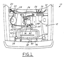
- FIGURE 1 is a top view of a vehicle having a cooling system according to a preferred embodiment of the present invention
- FIGURE 2 is a logic flow diagram of a method for controlling the electric water pump, electric fan, and other engine components according to a preferred embodiment of the present invention
- FIGURE 3 is a more detailed logic flow diagram of Step 160 of FIGURE 2.
- FIGURE 4 is a lookup table of Step 180 of FIGURE 2.
- the cooling system 12 has a powertrain control module 20, a computer control harness 22, a check engine lamp driver 24, a cylinder head temperature sensor 26, a check engine light 28, a vehicle speed sensor 30, a fuse panel 32, an electric water pump 34, an engine coolant sensor 36, an ambient temperature sensor 38, a pair of electric cooling fans 40, a flow control valve 42, a throttle position sensor 44, and a radiator 46.
- coolant enters the electric water pump 34 through a branch duct 50 from the radiator 46. Coolant is then pumped out of the water pump 34 through a return duct 52 and into the cooling passages (not shown) of the engine 48. The coolant flows through the engine to the flow control valve 42. Coolant will then flow back to the radiator 46 through the supply duct 54 or be bypassed through the branch duct 50 depending upon the engine coolant temperature as determined by the engine coolant temperature sensor 36.
- the flow control valve 42 directs the coolant through the branch duct 50. If the engine 48 is warm, the flow control valve 42 directs the coolant through the supply duct 54 to the radiator 46, where the coolant is cooled. In this way, the engine 48 quickly heats up to optimal operating conditions and is maintained at those conditions thereafter.
- the powertrain control module 20 operates to maintain the coolant within a predetermined range of temperatures. This may be accomplished in many ways. First, the electric cooling fan 40 could be turned on or off, or the speed increased or decreased, to ensure that the coolant is within the range of acceptable temperatures. Second, the electric water pump 34 speed could be increased or decreased to either cool or warm the engine 48. Third, the flow rate through the flow control valve 42 and into the radiator 46 could be increased to cool the engine 48 or decreased to warm the engine 48. Finally, a combination of two or all of these controls may be used.
- the present invention provides an optimal operating strategy for the cooling system 12 that incorporates thermal management, electrical load management, engine emissions, and fuel economy.
- a logic flow diagram for operating this cooling system 12 with an electric water pump 34, flow control valve 42 and electric fan 40 is discussed below.
- Step 100 the system 12 is started and initialized.
- the time is initially determined and marked as Time_A.
- Step 110 the Limited Operating Strategy for Engine Coolant Temperature (LOS_ECT) is set to its maximum value (LOS_ECT_HIGH).
- LOS_ECT_HIGH is set for a system 12 based on the desired high-end engine coolant temperature for the particular application for which it is used. For a preferred embodiment of the present invention, when used on an automobile system, LOS_ECT_HIGH is set to 250 degrees Fahrenheit (121 degrees Celsius).
- Step 120 the current time (Time_B) is determined.
- Step 130 Time_B is compared to Time_A. If there is not a difference of at least 50 milliseconds between Time_A and Time_B, the logic proceeds back to Step 120, otherwise the logic proceeds to Step 140, where Time_A is set equal to Time_B.
- Step 150 a determination is made as to whether the engine coolant temperature (ECT), as determined by the engine coolant temperature sensor 36, is greater than LOS_ECT_HIGH. If it is, proceed to Step 160, otherwise proceed to Step 180.
- ECT engine coolant temperature
- Step 160 the Limited Operating Strategy (LOS) is executed.
- FIGURE 3 is a more detailed diagram of Step 160.
- the powertrain control module 20 directs that the electric water pump 34 is set to its maximum speed (or maximum % duty cycle) in Step 300, the flow control valve 42 is set to its maximum value (corresponding to fully open, thereby directing all of the coolant to enter the radiator 46) in Step 301, and the electric cooling fan 40 is set to its maximum speed (or maximum % duty cycle) in Step 302.
- the air conditioning unit (not shown) is turned off (Step 304), the spark retard is turned on (Step 306), all non-regulatory loads are shed (Step 308), the torque converter lockup is turned on (Step 310), and the exhaust gas recirculation (EGR) valve is turned on (Step 312) in an effort to cool the engine 48 and cylinder heads (not shown) as quickly as possible to an acceptable temperature.
- non-regulatory loads may include a heated rear window, heated seats, rear seat entertainment devices, or any other optional electrical equipment typically found on vehicles.
- Step 170 hysteresis is taken into account in Step 170 by having the powertrain control module 20 set the LOS_ECT to its minimum value (LOS_ECT_LOW).
- the LOS_ECT_LOW is preferably approximately 10 degrees Fahrenheit lower than the LOS_ECT_HIGH, or approximately 240 degrees Fahrenheit (116 degrees Celsius). The logic then proceeds back to Step 120.
- Step 180 the actual engine coolant temperature as determined by engine coolant temperature sensor 36 is signaled to the powertrain control module 20 to set the water pump 34 speed, the flow control valve 42 opening, and the electric fan 40 speed.
- the values are predetermined and available to the logic in the form of a look-up table.
- Step 190 the LOS_ECT is set to its maximum value (LOS_ECT_HIGH) by the powertrain control module 20.
- Step 200 the powertrain control module 20 determines whether the key is on or off. If the key is on, proceed back to Step 120. If the key is off, Step 210 is implemented, in which the powertrain control module 20 turns on the electric water pump 34 and the electric fans 40 for a predetermined amount of time sufficient to circulate the coolant from the engine 48 to the radiator 46 to prevent the coolant from boiling over within the engine 48.
- the calibratable look-up table determines the proper duty cycle for the electric water pump 34 (as indicated by line 402) and for the electric fan 40 (as indicated by line 404) as a function of the engine coolant temperature.
- the duty cycles in the preferred embodiment for the electric water pump 34 range from 10% to 90%, with 10% corresponding to a pumping speed of approximately 1000 rpm and 90% corresponding to a pumping speed of approximately 5500 rpm for a 42V water pump.
- the electric fan 40 ranges from 0% to 100%, with 0% corresponding to the fan 40 is turned off and 90% corresponding to the maximum fan speed possible when the fans 40 are in operation.
- the look-up table of FIGURE 4 also directs the flow control valve 42 to an open position (wherein coolant flows through the supply duct 54 and into the radiator 46), shut position (wherein coolant does not flow through the radiator 46, instead flowing through the branch duct 50 to the electric water pump 34), or a position therebetween (wherein coolant flows through both the branch duct 50 and the supply duct 54).
- the powertrain control module 20 directs the electric pump 34 to pump at approximately 10% duty cycle based on the actual engine coolant temperature according to the look up table, while further directing the electric fan 40 to turn off.
- the duty cycle of the electric water pump 34 is increased from 10% to 80% in a substantially linear fashion according to a predetermined ramp rate.
- the powertrain control module 20 directs the electric fan 40 to switch on and the speed of the rotation to raise to 20% duty cycle.
- the duty cycle of the fan 40 and the pump 34 are increased according to the look-up table until they reach their maximum values of 90%.
- the powertrain control module 20 directs the flow control valve 42 according to the look up table to an open, closed or partially open position at various coolant temperatures, pump 34 speeds and fan 40 speeds. In this way, the engine 48 is cooled as rapidly as possible to optimize fuel economy, emissions, and electrical load usage.
- the powertrain control module 20 shuts off the electric fan 40. In the preferred embodiment of the present invention, this occurs at a vehicle speed of 48-mph or greater and an engine coolant temperature below 212 degrees Fahrenheit (100 degrees Celsius). The air flowing through the vehicle 10 at these speeds is then used to cool the coolant flowing through the radiator 46. This further increases fuel economy by decreasing the electrical load within the system 12. Further, the powertrain control module 20 directs the electric fan 40 to be turned off at less than the predetermined speed, where the ambient temperature, as measured by an ambient temperature sensor 38 and the engine coolant temperature, as measured by the engine coolant temperature sensor 36, are below a predetermined temperature.
- the logic flow diagram of FIGURE 2 could use cylinder head temperature (as opposed to engine coolant temperature) as measured by a cylinder head temperature sensor 26 to control the electric water pump 34 and electric fan 40 as a function of fuel economy, emissions, and electric load management.
- a system 12 is contemplated that uses both cylinder head temperature and engine coolant temperature to control the electric water pump 34, flow control valve 42 and electric fan 40 as a function of fuel economy, emissions, thermal management, and electric load management.
- the powertrain control module 20 may direct the electric water pump 34, flow control valve 42, or electric fan to run at slightly elevated engine 48 temperatures to improve some other engine parameter, such as fuel economy.
- the present invention provides an apparatus and method for controlling engine coolant temperature in a closed loop cooling system 12 that controls engine 48 coolant temperature or cylinder head temperature while optimizing electrical load management, thermal management, fuel economy, and emissions at all temperatures.
Landscapes
- Engineering & Computer Science (AREA)
- Chemical & Material Sciences (AREA)
- Combustion & Propulsion (AREA)
- Mechanical Engineering (AREA)
- General Engineering & Computer Science (AREA)
- Combined Controls Of Internal Combustion Engines (AREA)
- Control Of Vehicle Engines Or Engines For Specific Uses (AREA)
- Air-Conditioning For Vehicles (AREA)
Abstract
Description
Claims (13)
- A cooling system control apparatus for controlling the temperature of engine coolant in a coolant-cooled engine comprising:a radiator for cooling the engine coolant;at least one electric fan for supplying air to said radiator;an electric water pump for circulating said engine coolant through an engine cooling system circuit including said radiator;a flow control valve coupled between said engine and said electric water pump;a plurality of input sensors; anda powertrain control unit electrically coupled to said at least one electric fan, said flow control valve, said electric water pump and said plurality of input sensors, said powertrain control unit adapted to control the operation of said electric water pump, said flow control valve and said electric fan as a function of said input sensors to optimize fuel economy, emissions, thermal management and electrical load management.
- The apparatus of claim 1 further comprising an air conditioning unit electrically coupled to said powertrain control unit, wherein said powertrain control unit controls the operation of said air conditioning unit as a function of said input sensors to optimize fuel economy, emissions, thermal management and electrical load management.
- The apparatus of claim 1 further comprising a plurality of non-regulatory electrical load devices electrically coupled to said powertrain control unit, wherein said powertrain control unit controls the operation of said plurality of non-regulatory electrical load devices as a function of said input sensors to optimize fuel economy, emissions, thermal management and electrical load management.
- The apparatus of claim 1 further comprising an air conditioning unit and a plurality of non-regulatory electrical load devices electrically coupled to said powertrain control unit, wherein said powertrain control unit controls the operation of said air conditioning unit and said plurality of non-regulatory electrical load devices as a function of said input sensors to optimize fuel economy, emissions, thermal management and electrical load management.
- The apparatus of claim 1, wherein said input sensors are selected from a group consisting of an engine coolant sensor, a cylinder head temperature sensor, a vehicle speed sensor, an ambient temperature sensor, and a throttle position sensor.
- A method of controlling engine temperature in a closed circuit cooling system having an electric water pump, a flow control valve and an electric fan, the method comprising the steps of:adjusting the pumping speed of the electric water pump to optimize fuel economy, emissions, thermal management and electrical load management;adjusting the rotational speed of the electric fan to optimize fuel economy, emissions, thermal management and electrical load management; andadjusting the flow rate through the flow control valve to optimize fuel economy, emission, thermal management, and electrical load management.
- The method of claim 6 further comprising the steps of:adjusting an amount of spark retard as a function of fuel economy, emissions, thermal management and electrical load management;adjusting a torque converter lock-up as a function of fuel economy, emissions, thermal management, and electrical load management;adjusting an exhaust gas recirculation valve as a function of fuel economy, emissions, thermal management, and electrical load management; andshedding at least one of a plurality of non-regulatory electric loads as a function fuel economy, emissions, thermal management and electrical load management.
- The method of claim 6, further comprising the step of adjusting said pumping speed of the electric water pump as a function of engine coolant temperature, engine speed signal, vehicle speed, and ambient temperature.
- The method of claim 6, further comprising the step of adjusting said rotational speed of the electric fan as a function of engine coolant temperature, engine speed signal, vehicle speed, and ambient temperature.
- The method of claim 6, further comprising the step of adjusting the flow rate through the flow control valve as a function of engine coolant temperature, engine speed signal, vehicle speed, and ambient temperature.
- The method of claim 6, further comprising the step of adjusting said pumping speed of the electric water pump as a function of engine load signal.
- The method of claim 6, further comprising the step of adjusting said rotational speed of the electric fan as a function of engine load signal.
- The method of claim 6, further comprising the step of adjusting said flow rate through said flow control valve as a function of engine load signal.
Applications Claiming Priority (2)
| Application Number | Priority Date | Filing Date | Title |
|---|---|---|---|
| US612355 | 1984-05-21 | ||
| US09/612,355 US6374780B1 (en) | 2000-07-07 | 2000-07-07 | Electric waterpump, fluid control valve and electric cooling fan strategy |
Publications (2)
| Publication Number | Publication Date |
|---|---|
| EP1170477A2 true EP1170477A2 (en) | 2002-01-09 |
| EP1170477A3 EP1170477A3 (en) | 2003-06-25 |
Family
ID=24452805
Family Applications (1)
| Application Number | Title | Priority Date | Filing Date |
|---|---|---|---|
| EP01116333A Withdrawn EP1170477A3 (en) | 2000-07-07 | 2001-07-05 | Electric waterpump, fluid control valve and electric cooling fan strategy |
Country Status (2)
| Country | Link |
|---|---|
| US (1) | US6374780B1 (en) |
| EP (1) | EP1170477A3 (en) |
Cited By (3)
| Publication number | Priority date | Publication date | Assignee | Title |
|---|---|---|---|---|
| FR2874549A1 (en) * | 2004-08-20 | 2006-03-03 | Honda Motor Co Ltd | FUEL CELL VEHICLE |
| WO2010116108A1 (en) * | 2009-04-09 | 2010-10-14 | Renault Sas | Cooling device for a motor vehicle |
| WO2012012422A3 (en) * | 2010-07-20 | 2012-04-26 | Cooper Technologies Company | Load management aware fan control |
Families Citing this family (44)
| Publication number | Priority date | Publication date | Assignee | Title |
|---|---|---|---|---|
| DE10044175A1 (en) * | 2000-09-07 | 2002-03-21 | Deere & Co | Pre-assembled cladding unit for a vehicle cabin |
| US6450275B1 (en) * | 2000-11-02 | 2002-09-17 | Ford Motor Company | Power electronics cooling for a hybrid electric vehicle |
| US6802283B2 (en) | 2002-07-22 | 2004-10-12 | Visteon Global Technologies, Inc. | Engine cooling system with variable speed fan |
| US6668766B1 (en) | 2002-07-22 | 2003-12-30 | Visteon Global Technologies, Inc. | Vehicle engine cooling system with variable speed water pump |
| US6668764B1 (en) | 2002-07-29 | 2003-12-30 | Visteon Global Techologies, Inc. | Cooling system for a diesel engine |
| US6745726B2 (en) | 2002-07-29 | 2004-06-08 | Visteon Global Technologies, Inc. | Engine thermal management for internal combustion engine |
| US20040075077A1 (en) * | 2002-10-21 | 2004-04-22 | Jean-Pierre Maes | Method for cooling high temperature engines |
| US7579805B2 (en) * | 2004-01-26 | 2009-08-25 | Hitachi, Ltd. | Semiconductor device |
| GB2425619B (en) * | 2005-03-22 | 2007-05-02 | Visteon Global Tech Inc | Method of engine cooling |
| JP2007016659A (en) * | 2005-07-06 | 2007-01-25 | Kobelco Contstruction Machinery Ltd | Control device for cooling fan |
| US7467605B2 (en) * | 2006-05-26 | 2008-12-23 | Visteon Global Technologies, Inc. | Thermal energy recovery and management system |
| JP4938436B2 (en) * | 2006-12-15 | 2012-05-23 | カルソニックカンセイ株式会社 | Vehicle cooling fan control system |
| JP4325669B2 (en) * | 2006-12-26 | 2009-09-02 | トヨタ自動車株式会社 | Air conditioner for vehicles |
| US8566375B1 (en) * | 2006-12-27 | 2013-10-22 | The Mathworks, Inc. | Optimization using table gradient constraints |
| JP4277046B2 (en) * | 2007-02-28 | 2009-06-10 | トヨタ自動車株式会社 | Cooling device for internal combustion engine |
| US8133156B2 (en) * | 2007-11-16 | 2012-03-13 | Caterpillar Inc. | System and method for controlling machine component temperatures |
| US8196553B2 (en) * | 2008-01-30 | 2012-06-12 | Chrysler Group Llc | Series electric-mechanical water pump system for engine cooling |
| US20090205588A1 (en) * | 2008-02-15 | 2009-08-20 | Bilezikjian John P | Internal combustion engine with variable speed coolant pump |
| US20100056330A1 (en) * | 2008-08-29 | 2010-03-04 | Caterpillar Inc. | Controlling stationary machine powertrain warmup |
| US20100131152A1 (en) * | 2008-09-05 | 2010-05-27 | Sylvain Castonguay | System, device and method for automatically stopping and starting engines of motor vehicles |
| US8333172B2 (en) * | 2008-12-23 | 2012-12-18 | Caterpillar Inc. | Cooling system |
| US8203274B2 (en) | 2010-08-13 | 2012-06-19 | De Castro Erwin L | LED and thermal management module for a vehicle headlamp |
| US8549838B2 (en) | 2010-10-19 | 2013-10-08 | Cummins Inc. | System, method, and apparatus for enhancing aftertreatment regeneration in a hybrid power system |
| US8833496B2 (en) | 2010-12-20 | 2014-09-16 | Cummins Inc. | System, method, and apparatus for battery pack thermal management |
| US8742701B2 (en) | 2010-12-20 | 2014-06-03 | Cummins Inc. | System, method, and apparatus for integrated hybrid power system thermal management |
| US9096207B2 (en) | 2010-12-31 | 2015-08-04 | Cummins Inc. | Hybrid vehicle powertrain cooling system |
| US9043060B2 (en) | 2010-12-31 | 2015-05-26 | Cummins Inc. | Methods, systems, and apparatuses for driveline load management |
| US8473177B2 (en) | 2010-12-31 | 2013-06-25 | Cummins, Inc. | Apparatuses, methods, and systems for thermal management of hybrid vehicle SCR aftertreatment |
| CN117048579A (en) | 2011-01-13 | 2023-11-14 | 卡明斯公司 | Systems, methods, and apparatus for controlling power output distribution in a hybrid powertrain |
| US20130094972A1 (en) * | 2011-10-18 | 2013-04-18 | Ford Global Technologies, Llc | Climate Thermal Load Based Minimum Flow Rate Water Pump Control |
| KR101427955B1 (en) * | 2013-04-08 | 2014-08-11 | 현대자동차 주식회사 | Method for controlling water pump of vehicle and system thereof |
| KR101655579B1 (en) * | 2014-11-26 | 2016-09-07 | 현대자동차주식회사 | Apparatus for controlling cooling pump of fuel cell system |
| US9926833B2 (en) * | 2016-05-06 | 2018-03-27 | General Electric Company | System and method for controlling a vehicle |
| US10605151B2 (en) * | 2016-06-09 | 2020-03-31 | GM Global Technology Operations LLC | Electric pump operating strategy |
| US10471793B2 (en) | 2016-10-12 | 2019-11-12 | Ford Global Technologies, Llc | Seat mounts for side load spring on a twist beam axle |
| DE102016221169A1 (en) * | 2016-10-27 | 2018-05-03 | Ford Global Technologies, Llc | Method for operating a vehicle air conditioning system |
| KR20190068353A (en) * | 2017-12-08 | 2019-06-18 | 현대자동차주식회사 | Engine device for vehicle |
| US10982627B2 (en) * | 2019-05-16 | 2021-04-20 | International Engine Intellectual Property Company, Llc. | Variable speed coolant pump control strategy |
| CN112829567B (en) * | 2019-11-25 | 2022-06-17 | 江铃汽车股份有限公司 | Control method for cooling system of electric automobile |
| CN113550819B (en) * | 2020-04-24 | 2022-07-12 | 广州汽车集团股份有限公司 | A kind of engine warm-up control method and device |
| CN112467243B (en) * | 2020-11-12 | 2022-07-12 | 浙江合众新能源汽车有限公司 | Battery pack cooling control method and device |
| CN113606030B (en) * | 2021-09-03 | 2022-07-12 | 苏州睿昕汽车配件有限公司 | A kind of control method of engine cooling system |
| US12261562B2 (en) * | 2022-05-31 | 2025-03-25 | Cooper-Standard Automotive Inc. | Apparatus and method for the integrated control of a thermal management system |
| CN116537932A (en) * | 2023-06-16 | 2023-08-04 | 长城汽车股份有限公司 | Thermal management method and vehicle |
Family Cites Families (12)
| Publication number | Priority date | Publication date | Assignee | Title |
|---|---|---|---|---|
| JPS57342A (en) * | 1980-06-02 | 1982-01-05 | Nissan Motor Co Ltd | Engine controller for vehicle mounting lock-up automatic speed changer |
| JPS58124017A (en) | 1982-01-19 | 1983-07-23 | Nippon Denso Co Ltd | Cooling system controller of engine |
| SE454115B (en) | 1982-09-13 | 1988-03-28 | Wallac Oy | HOMOGENIC PHASE ANALYSIS WITH LANTANIDE KELAT AS BRAND SUBSTANCE |
| JPS60113017A (en) | 1983-11-25 | 1985-06-19 | Toyota Motor Corp | Operation control method for cooling fan of 2-system cooling type internal-combustion engine |
| JPS6183426A (en) | 1984-09-29 | 1986-04-28 | Nissan Motor Co Ltd | Evaporative cooling apparatus for internal-combustion engine |
| JPS6183413A (en) | 1984-09-29 | 1986-04-28 | Nissan Motor Co Ltd | High-temperature anomaly avoiding controller in evaporative cooling apparatus of internal-combustion engine |
| US4665319A (en) * | 1985-03-21 | 1987-05-12 | General Electric Company | Self-propelled traction vehicle with low fuel consumption while idling |
| JPS62247112A (en) | 1986-03-28 | 1987-10-28 | Aisin Seiki Co Ltd | Cooling system control device for internal combustion engine |
| DE4104093A1 (en) * | 1991-02-11 | 1992-08-13 | Behr Gmbh & Co | COOLING SYSTEM FOR A COMBUSTION ENGINE VEHICLE |
| DE19508104C2 (en) | 1995-03-08 | 2000-05-25 | Volkswagen Ag | Method for regulating a cooling circuit of an internal combustion engine |
| DE19508102C1 (en) | 1995-03-08 | 1996-07-25 | Volkswagen Ag | Method for regulating a cooling circuit of an internal combustion engine, in particular for motor vehicles |
| US6178928B1 (en) * | 1998-06-17 | 2001-01-30 | Siemens Canada Limited | Internal combustion engine total cooling control system |
-
2000
- 2000-07-07 US US09/612,355 patent/US6374780B1/en not_active Expired - Lifetime
-
2001
- 2001-07-05 EP EP01116333A patent/EP1170477A3/en not_active Withdrawn
Cited By (6)
| Publication number | Priority date | Publication date | Assignee | Title |
|---|---|---|---|---|
| FR2874549A1 (en) * | 2004-08-20 | 2006-03-03 | Honda Motor Co Ltd | FUEL CELL VEHICLE |
| CN100374315C (en) * | 2004-08-20 | 2008-03-12 | 本田技研工业株式会社 | fuel cell vehicle |
| US7481288B2 (en) | 2004-08-20 | 2009-01-27 | Honda Motor Co., Ltd. | Cooling Arrangement for a fuel-cell vehicle |
| WO2010116108A1 (en) * | 2009-04-09 | 2010-10-14 | Renault Sas | Cooling device for a motor vehicle |
| FR2944238A1 (en) * | 2009-04-09 | 2010-10-15 | Renault Sas | COOLING DEVICE FOR MOTOR VEHICLE |
| WO2012012422A3 (en) * | 2010-07-20 | 2012-04-26 | Cooper Technologies Company | Load management aware fan control |
Also Published As
| Publication number | Publication date |
|---|---|
| EP1170477A3 (en) | 2003-06-25 |
| US6374780B1 (en) | 2002-04-23 |
Similar Documents
| Publication | Publication Date | Title |
|---|---|---|
| US6374780B1 (en) | Electric waterpump, fluid control valve and electric cooling fan strategy | |
| US6668766B1 (en) | Vehicle engine cooling system with variable speed water pump | |
| US6817330B1 (en) | Internal combustion engine control apparatus | |
| US6530347B2 (en) | Cooling apparatus for liquid-cooled internal combustion engine | |
| US8695541B2 (en) | Cooling system for internal combustion engine | |
| US6802283B2 (en) | Engine cooling system with variable speed fan | |
| US7128026B2 (en) | Method for controlling the heat in an automotive internal combustion engine | |
| US20050028756A1 (en) | Engine cooling system | |
| JP2002227644A (en) | System of controlling electric coolant pump for hybrid electric vehicle | |
| JP2006528297A (en) | Automotive internal combustion engine | |
| JP2011116366A (en) | Auxiliary pump scheme of cooling system in hybrid electric vehicle | |
| JPH0444084B2 (en) | ||
| JP2004150277A (en) | Ventilator for heat exchanger for vehicle, and control method thereof | |
| JP2008248715A (en) | Electric water pump control apparatus for automobile and air conditioning system for automobile equipped with this control apparatus | |
| US10753268B2 (en) | Intercooler cooling apparatus and method for controlling transmission fluid and air conditioner refrigerant temperature | |
| JP2004360509A (en) | Cooling device for internal combustion engine | |
| US6394045B1 (en) | Device for regulating the cooling of a motor-vehicle internal-combustion engine | |
| RU2518764C1 (en) | Device and method for heating of heat carrier circulating in cooling system | |
| EP1270892A2 (en) | Water pump with electronically controlled viscous coupling drive | |
| US6725812B1 (en) | Water pump driven by viscous coupling | |
| JP7623840B2 (en) | Vehicle temperature control system | |
| US20040187505A1 (en) | Integrated cooling system | |
| EP0841203A2 (en) | Heating apparatus for vehicle | |
| JP3319304B2 (en) | Vehicle heating system | |
| JPH04259622A (en) | Engine cooling device |
Legal Events
| Date | Code | Title | Description |
|---|---|---|---|
| PUAI | Public reference made under article 153(3) epc to a published international application that has entered the european phase |
Free format text: ORIGINAL CODE: 0009012 |
|
| AK | Designated contracting states |
Kind code of ref document: A2 Designated state(s): AT BE CH CY DE DK ES FI FR GB GR IE IT LI LU MC NL PT SE TR |
|
| AX | Request for extension of the european patent |
Free format text: AL;LT;LV;MK;RO;SI |
|
| PUAL | Search report despatched |
Free format text: ORIGINAL CODE: 0009013 |
|
| AK | Designated contracting states |
Designated state(s): AT BE CH CY DE DK ES FI FR GB GR IE IT LI LU MC NL PT SE TR |
|
| AX | Request for extension of the european patent |
Extension state: AL LT LV MK RO SI |
|
| 17P | Request for examination filed |
Effective date: 20030811 |
|
| AKX | Designation fees paid |
Designated state(s): DE FR GB |
|
| STAA | Information on the status of an ep patent application or granted ep patent |
Free format text: STATUS: THE APPLICATION HAS BEEN WITHDRAWN |
|
| 18W | Application withdrawn |
Effective date: 20040504 |