EP1169910A1 - Electric motor vehicle - Google Patents
Electric motor vehicle Download PDFInfo
- Publication number
- EP1169910A1 EP1169910A1 EP01116174A EP01116174A EP1169910A1 EP 1169910 A1 EP1169910 A1 EP 1169910A1 EP 01116174 A EP01116174 A EP 01116174A EP 01116174 A EP01116174 A EP 01116174A EP 1169910 A1 EP1169910 A1 EP 1169910A1
- Authority
- EP
- European Patent Office
- Prior art keywords
- battery
- armrest
- electric motor
- motor vehicle
- battery storage
- Prior art date
- Legal status (The legal status is an assumption and is not a legal conclusion. Google has not performed a legal analysis and makes no representation as to the accuracy of the status listed.)
- Granted
Links
Images



Classifications
-
- B—PERFORMING OPERATIONS; TRANSPORTING
- B62—LAND VEHICLES FOR TRAVELLING OTHERWISE THAN ON RAILS
- B62K—CYCLES; CYCLE FRAMES; CYCLE STEERING DEVICES; RIDER-OPERATED TERMINAL CONTROLS SPECIALLY ADAPTED FOR CYCLES; CYCLE AXLE SUSPENSIONS; CYCLE SIDECARS, FORECARS, OR THE LIKE
- B62K5/00—Cycles with handlebars, equipped with three or more main road wheels
- B62K5/003—Cycles with four or more wheels, specially adapted for disabled riders, e.g. personal mobility type vehicles with four wheels
- B62K5/007—Cycles with four or more wheels, specially adapted for disabled riders, e.g. personal mobility type vehicles with four wheels power-driven
-
- B—PERFORMING OPERATIONS; TRANSPORTING
- B62—LAND VEHICLES FOR TRAVELLING OTHERWISE THAN ON RAILS
- B62J—CYCLE SADDLES OR SEATS; AUXILIARY DEVICES OR ACCESSORIES SPECIALLY ADAPTED TO CYCLES AND NOT OTHERWISE PROVIDED FOR, e.g. ARTICLE CARRIERS OR CYCLE PROTECTORS
- B62J1/00—Saddles or other seats for cycles; Arrangement thereof; Component parts
- B62J1/28—Other additional equipment, e.g. back-rests for children
-
- B—PERFORMING OPERATIONS; TRANSPORTING
- B62—LAND VEHICLES FOR TRAVELLING OTHERWISE THAN ON RAILS
- B62J—CYCLE SADDLES OR SEATS; AUXILIARY DEVICES OR ACCESSORIES SPECIALLY ADAPTED TO CYCLES AND NOT OTHERWISE PROVIDED FOR, e.g. ARTICLE CARRIERS OR CYCLE PROTECTORS
- B62J43/00—Arrangements of batteries
- B62J43/10—Arrangements of batteries for propulsion
- B62J43/16—Arrangements of batteries for propulsion on motorcycles or the like
-
- B—PERFORMING OPERATIONS; TRANSPORTING
- B62—LAND VEHICLES FOR TRAVELLING OTHERWISE THAN ON RAILS
- B62J—CYCLE SADDLES OR SEATS; AUXILIARY DEVICES OR ACCESSORIES SPECIALLY ADAPTED TO CYCLES AND NOT OTHERWISE PROVIDED FOR, e.g. ARTICLE CARRIERS OR CYCLE PROTECTORS
- B62J43/00—Arrangements of batteries
- B62J43/20—Arrangements of batteries characterised by the mounting
- B62J43/23—Arrangements of batteries characterised by the mounting dismounted when charging
-
- B—PERFORMING OPERATIONS; TRANSPORTING
- B62—LAND VEHICLES FOR TRAVELLING OTHERWISE THAN ON RAILS
- B62K—CYCLES; CYCLE FRAMES; CYCLE STEERING DEVICES; RIDER-OPERATED TERMINAL CONTROLS SPECIALLY ADAPTED FOR CYCLES; CYCLE AXLE SUSPENSIONS; CYCLE SIDECARS, FORECARS, OR THE LIKE
- B62K2204/00—Adaptations for driving cycles by electric motor
Definitions
- the present invention relates to an electric motor vehicle including a battery as the power source, and in particular relates to improvement in the battery mounting structure.
- Electric motor vehicles including senior cars, motor chairs, etc., have a battery for supplying electric power to the motor for driving the wheels.
- This battery is usually mounted at the battery mounting portion arranged at the back of the chair (see Japanese Patent Application Laid-Open Hei 11 No.76313, Japanese Patent Application Laid-Open Hei 12 No.51279).
- the battery in the conventional battery mounting arrangements is mounted at the specially arranged battery mounting portion as stated above, a certain space for the battery mounting portion is needed, and the battery is mounted with a large part of it exposed. Therefore, it is necessary to have a separate fixing device in order to attach the battery to prevent movement. Also, since the battery mounting portion is located at a low site, the user needs to bend over to mount or remove the battery. In particular, it has been difficult for a senior user or disabled person to perform replacement of the battery by themselves.
- the present invention has been devised in view of the above conventional drawbacks and it is therefore an object of the present invention to provide an electric motor vehicle in which the battery is provided as a cartridge and can be simply and easily mounted or removed in vacant space inside the armrests.
- the present invention is configured as follows:
- an electric motor vehicle with a battery for supplying electric energy to the motor for driving the wheels is characterized in that a pair of armrest bodies is arranged upright, each armrest body having a longer dimension in the front-to-rear direction of the vehicle than the dimension in width when viewed from the top, each armrest has a hollow compartment for battery storage in which the battery can be inserted or removed from the top thereof and has an armrest cushion on the top thereof which serves as a lid that can open and close the battery storage compartment.
- the electric motor vehicle having the above first feature is characterized in that the armrest cushion is hinged at the top end of the armrest body so as to open and close the battery storage compartment, at least the front-side piping of the armrest frame is exposed to the interior of the battery storage compartment so as to guide the battery by fitting the piping to the depressed portion formed at least on the front side of the battery.
- the electric motor vehicle having the above first feature is characterized in that the armrest body and armrest cushion are inclined forwards so that the battery set in the battery storage compartment can be accommodated in close contact with the armrest frame.
- the electric motor vehicle having the above second feature is characterized in that the armrest body and armrest cushion are inclined forwards so that the battery set in the battery storage compartment can be accommodated in close contact with the armrest frame.
- the electric motor vehicle having the above first feature is characterized in that the battery is a cartridge type having a handle on the top thereof, the handle projects out above the battery storage portion when set in the battery storage compartment and can be covered and urged downward by the armrest cushion when the armrest cushion is closed.
- the electric motor vehicle having the above second feature is characterized in that the battery is a cartridge type having a handle on the top thereof, the handle projects out above the battery storage portion when set in the battery storage compartment and can be covered and urged downward by the armrest cushion when the armrest cushion is closed.
- the electric motor vehicle having the above third feature is characterized in that the battery is a cartridge type having a handle on the top thereof, the handle projects out above the battery storage portion when set in the battery storage compartment and can be covered and urged downward by the armrest cushion when the armrest cushion is closed.
- the electric motor vehicle having the above fourth feature is characterized in that the battery is a cartridge type having a handle on the top thereof, the handle projects out above the battery storage portion when set in the battery storage compartment and can be covered and urged downward by the armrest cushion when the armrest cushion is closed.
- the electric motor vehicle having the above first feature is characterized in that a stuff bucket having the same outside dimensions as the battery and formed with a depressed portion on the front side is set in either one of the left and right battery storage compartments of the armrest bodies.
- the electric motor vehicle having the above second feature is characterized in that a stuff bucket having the same outside dimensions as the battery and formed with a depressed portion on the front side is set in either one of the left and right battery storage compartments of the armrest bodies.
- the electric motor vehicle having the above third feature is characterized in that a stuff bucket having the same outside dimensions as the battery and formed with a depressed portion on the front side is set in either one of the left and right battery storage compartments of the armrest bodies.
- the electric motor vehicle having the above fourth feature is characterized in that a stuff bucket having the same outside dimensions as the battery and formed with a depressed portion on the front side is set in either one of the left and right battery storage compartments of the armrest bodies.
- the electric motor vehicle having the above fifth feature is characterized in that a stuff bucket having the same outside dimensions as the battery and formed with a depressed portion on the front side is set in either one of the left and right battery storage compartments of the armrest bodies.
- the electric motor vehicle having the above sixth feature is characterized in that a stuff bucket having the same outside dimensions as the battery and formed with a depressed portion on the front side is set in either one of the left and right battery storage compartments of the armrest bodies.
- the electric motor vehicle having the above seventh feature is characterized in that a stuff bucket having the same outside dimensions as the battery and formed with a depressed portion on the front side is set in either one of the left and right battery storage compartments of the armrest bodies.
- the electric motor vehicle having the above eighth feature is characterized in that a stuff bucket having the same outside dimensions as the battery and formed with a depressed portion on the front side is set in either one of the left and right battery storage compartments of the armrest bodies.
- the battery storage portions are formed inside the armrests arranged on both sides of the seat, it is possible to efficiently use the empty spaces inside the armrests. Further since the storage compartment is located under the armrest cushion on which the elbow is put, the battery can be set at a height that allows the user to easily perform replacement of the battery, for instance provided as a cartridge, without bending over.
- the depressed portions formed at least on the front side of the battery can be guided by the armrest frame, this configuration allows the battery to be inserted easily, in alignment, and be mounted and removed easily and prevents the battery from rattling inside the battery storage when moving or in other occasions.
- the handle Since the top handle of the battery projects out above the battery storage and can be covered by the armrest cushion, the handle juts out from the top of the armrest body to be easily held when the armrest cushion is opened. Since the handle can be covered and pressed down by the armrest cushion when the armrest cushion is closed, it is possible to prevent the battery from rattling inside the battery storage and maintain good electric contact with the battery.
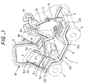
- Fig.1 is a perspective view showing a bodywork frame of an electric motor vehicle according to one embodiment of the present invention.
- Fig.2 is a side view showing an electric motor vehicle according to the embodiment.
- Fig.3 is a side view showing an armrest in detail.
- Fig.4 is a top view showing the armrest, viewed in the IV direction in Fig.3.
- Fig.5 is a sectional view cut along a plane V-V in Fig.3.
- Fig. 6 is a side view partially showing an electric motor vehicle according to another embodiment.
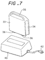
- Fig. 7 is a perspective view showing a battery and its charger.
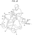
- Fig.8 is a perspective view showing the operations of mounting and removing the battery to or from an electric motor vehicle.
- Fig.9 is an illustrative view showing a box formed in one armrest.
- the electric motor vehicle such as a wheelchair according to the embodiment has a pair of plate-like armrest bodies 22 arranged on both sides, right and left, of a seat(seat base) 20 so as to embrace the user and includes a relatively lightweight, high-density battery 33(e.g., Ni-MH, lithium ion batteries) arranged inside the armrest body with its top covered by an armrest cushion so as to enable the user to replace the battery by their hands.
- the bodywork of the electric motor vehicle has a flat floor 46 located at the lower portion in front of the seat as a footrest and for sitting comfort and has a rising portion for the front structure, so that it assumes an overall U-shaped configuration when viewed from the side.
- the bodywork frame, designated at 1, which is made up of pipes to constitute the bodywork of the electric motor vehicle includes: a pair of main frames 5, 5 arranged on the left and right, each having a cranked shape with its center indented downwards, for suspending front wheels 2, 2 and rear wheels 3,3 from above and spanning over between the front wheels 2 and rear wheels 3; pairs of front and rear armrest frames 6a and 6b fixed in the rear part of each of the main frames 5, 5 and extended upward and slightly forwards; a U-shaped seat frame 7 which is positioned with the rear side open between right armrest frames 6a, 6b and left armrest frames 6a, 6b and is attached to their mid points so as to connect them and support the seat cushion thereon; and an inverted U-shaped back seat frame 9 attached to the upper positions of rear armrest frames 6b via hinges 8.
- a fixture plate 4 is arranged between the front portions of left and right main frames 5, 5 with a steering shaft 10 for front wheel steerage attached at the center thereof and extended upward. Attached at the top of this steering shaft 10 is a universal joint 11, which is joined to a handle shaft 12. A steering handle 14 is fixed to handle shaft 12. Steering shaft 10 is coupled with front wheels 2 by means of a steering mechanism 13(see Fig.2) so as to be able to control steering.
- a drive unit 45 having an electric motor as a drive source is arranged on the axle of rear wheels 3 under seat base 20.
- FIG.2 As shown in Fig.2, all the parts of the bodywork frame 1 and shafts 10 and 12 are externally covered by a relatively hard, resin-made or metallic cover structure 15, forming an electric motor vehicle body 16(see Fig.8).
- Back seat frame 9 is upholstered with cushions and covered by a soft cladding cover 17, forming a back seat 18.
- Seat base 20 made up of cushions covered by a soft cladding is attached on seat frame 7.
- armrest frames 6a, 6b are provided inclined forwards. These armrest frames 6a, 6b are cladded by a relatively hard cover element 21 made up of resin or the like, forming armrest body 22(see Fig.8).
- An armrest cushion 25 which is formed of a front-to-rear long plate covered by a cushioned cover is placed over the top of the armrest body 22.
- This armrest cushion 25 is pivotally attached to armrest frame 6b by means of a hinge 26 so as to cover or uncover the top opening of armrest body 22 as it turns.
- This armrest body 22 has a hollow space therein which serves as a battery storage compartment 23. Armrest frame 6a is bent forward at a partway position forming a bent portion 27.
- a battery supporting plate 30 is attached between the aforementioned front and rear armrest frames 6a and 6b.
- This battery supporting plate 30 is joined to and at right angles with front and rear armrest frames 6a and 6b. Hence this battery supporting plate 30 is also inclined forwards.
- Electrode terminals 31 are formed on the top face of battery supporting plate 30. These terminals 31 are connected to a main controller 32(see Figs.1 and 2) by means of an unillustrated wire harness such as electric cables.
- Main controller 32 is placed on the right side of fixture plate 4 while a vent hole 15a is formed on external body cover 15 so as to permit cooling air to pass therethrough.
- Cartridge type battery 33 is accommodated in battery storage portion 23. As shown in Fig.7, this battery 33 has depressed portions 34 formed on both the front and rear sides with a handle 35 on the top. Battery 33 further has electrodes 36 on the undersurface with elastic cushions formed around the electrodes or at appropriate positions on the underside thereof.
- the type of this battery 33 is not limited but a lightweight, high-density battery such as a Ni-MH battery or lithium-ion battery is preferably used.
- the height of the armrest of a typical wheel chair from the ground level is about 700 mm, and this is a convenient height for the user in a standing position to perform replacement of the battery, as in this electric motor vehicle shown in Fig. 8. More specifically, setting of battery 33 into battery storage portion 33 is performed by uplifting armrest cushion 25 so as to open the top of battery storage compartment 23 and inserting battery 33 into battery storage compartment 23 by gripping handle 35.
- the battery 33 slides with one of the depressed portions 34 on both sides of the battery being guided by bent portion 27 of armrest frame 6a and stops and is held by supporting plate 30, and electrodes 36, at the same time, come into contact with terminals 31 to establish conduction.
- handle 35 When battery 33 is accommodated in place, handle 35 is projected beyond the upper boundary, designated at 22a (the abutment face against armrest cushion 25), of armrest body 22.
- armrest cushion 25 When armrest cushion 25 is closed under this condition, handle 35 is pressed down by an elastic element such as rubber or a spring provided on the underside of armrest cushion 25 so that electrodes 36 come into close contact with terminals 31, to thereby maintain good conduction.
- rubber cushions may be provided on the underside of battery 33 so as to protect the battery from impacts. Since battery supporting plate 30 is inclined forwards, battery 33 continues being pressed against armrest frame 6a(see Fig.5) so that the battery is positively held without movement.
- the height of armrest body 22 can be set at about 700 mm, and as shown in Fig.8, this allows a normal user to mount or remove battery 33 without bending over.
- each armrest body is integrally extended forwards from the fender of the rear wheel to embrace the user.
- a seat of this fixed type has the advantage of allowing the disabled user to feel comforted by the sensation of being held.
- Another supporting plate 38 is arranged approximately horizontally below seat base 20 so as to utilize the upper space for a multi-purpose storage 39.
- a door 41 that opens upward to the rear is provided in the opening of this multi-purpose storage 39.
- This multipurpose storage 39 may accommodate a spare battery or other parts, for example.
- a charger 40 may be kept. For charging, the charger can be taken out from multipurpose storage 39 and set with its plug 42 connected to the power socket and with battery 33 in place, as shown in Fig.8.
- Fig.6 shows an armrest and its surroundings from an electric motor vehicle according to another embodiment of the present invention, in which the rear-side armrest frame 6b also has a bent portion 27 so that depressed portions 34 on both the front and rear sides of battery 33 can be guided along these armrest frames 6a and 6b.
- This arrangement holds battery 33 from both the front and rear, preventing the battery from rattling in battery storage portion 23 in a more reliable manner.
- one battery 33 may be set in one of left or right armrest body 22 while a container having the same outside dimensions as battery 33 may be set in the other armrest body 22 as a stuff box 48. This increases the storage space hence, making it possible and convenient to load various items.
- the present invention since battery accommodation spaces are formed inside the armrests arranged on both sides of the seat, it is possible to efficiently use the empty spaces inside the armrests and the battery is set at a height that allows the user to easily perform replacement of the battery without bending over.
- the top handle of the battery projects out above the battery storage portion and can be pressed down by the armrest cushion when the armrest cushion is closed, it is possible to prevent the battery from rattling inside the battery storage and maintain good electric contact.
Landscapes
- Engineering & Computer Science (AREA)
- Mechanical Engineering (AREA)
- Arrangement Or Mounting Of Propulsion Units For Vehicles (AREA)
- Automatic Cycles, And Cycles In General (AREA)
- Seats For Vehicles (AREA)
- Battery Mounting, Suspending (AREA)
Abstract
Description
- The present invention relates to an electric motor vehicle including a battery as the power source, and in particular relates to improvement in the battery mounting structure.
- Electric motor vehicles including senior cars, motor chairs, etc., have a battery for supplying electric power to the motor for driving the wheels. This battery is usually mounted at the battery mounting portion arranged at the back of the chair (see Japanese Patent Application Laid-Open Hei 11 No.76313, Japanese Patent Application Laid-Open Hei 12 No.51279). There is another known configuration in which batteries are mounted in the battery mounting portions arranged under the armrests on both sides of the seat.
- Since the battery in the conventional battery mounting arrangements is mounted at the specially arranged battery mounting portion as stated above, a certain space for the battery mounting portion is needed, and the battery is mounted with a large part of it exposed. Therefore, it is necessary to have a separate fixing device in order to attach the battery to prevent movement. Also, since the battery mounting portion is located at a low site, the user needs to bend over to mount or remove the battery. In particular, it has been difficult for a senior user or disabled person to perform replacement of the battery by themselves.
- The present invention has been devised in view of the above conventional drawbacks and it is therefore an object of the present invention to provide an electric motor vehicle in which the battery is provided as a cartridge and can be simply and easily mounted or removed in vacant space inside the armrests.
- In order to achieve the above object, the present invention is configured as follows:
- In accordance with the first aspect of the present invention, an electric motor vehicle with a battery for supplying electric energy to the motor for driving the wheels , is characterized in that a pair of armrest bodies is arranged upright, each armrest body having a longer dimension in the front-to-rear direction of the vehicle than the dimension in width when viewed from the top, each armrest has a hollow compartment for battery storage in which the battery can be inserted or removed from the top thereof and has an armrest cushion on the top thereof which serves as a lid that can open and close the battery storage compartment.
- In accordance with the second aspect of the present invention, the electric motor vehicle having the above first feature is characterized in that the armrest cushion is hinged at the top end of the armrest body so as to open and close the battery storage compartment, at least the front-side piping of the armrest frame is exposed to the interior of the battery storage compartment so as to guide the battery by fitting the piping to the depressed portion formed at least on the front side of the battery.
- In accordance with the third aspect of the present invention, the electric motor vehicle having the above first feature is characterized in that the armrest body and armrest cushion are inclined forwards so that the battery set in the battery storage compartment can be accommodated in close contact with the armrest frame.
- In accordance with the fourth aspect of the present invention, the electric motor vehicle having the above second feature is characterized in that the armrest body and armrest cushion are inclined forwards so that the battery set in the battery storage compartment can be accommodated in close contact with the armrest frame.
- In accordance with the fifth aspect of the present invention, the electric motor vehicle having the above first feature is characterized in that the battery is a cartridge type having a handle on the top thereof, the handle projects out above the battery storage portion when set in the battery storage compartment and can be covered and urged downward by the armrest cushion when the armrest cushion is closed.
- In accordance with the sixth aspect of the present invention, the electric motor vehicle having the above second feature is characterized in that the battery is a cartridge type having a handle on the top thereof, the handle projects out above the battery storage portion when set in the battery storage compartment and can be covered and urged downward by the armrest cushion when the armrest cushion is closed.
- In accordance with the seventh aspect of the present invention, the electric motor vehicle having the above third feature is characterized in that the battery is a cartridge type having a handle on the top thereof, the handle projects out above the battery storage portion when set in the battery storage compartment and can be covered and urged downward by the armrest cushion when the armrest cushion is closed.
- In accordance with the eighth aspect of the present invention, the electric motor vehicle having the above fourth feature is characterized in that the battery is a cartridge type having a handle on the top thereof, the handle projects out above the battery storage portion when set in the battery storage compartment and can be covered and urged downward by the armrest cushion when the armrest cushion is closed.
- In accordance with the ninth aspect of the present invention, the electric motor vehicle having the above first feature is characterized in that a stuff bucket having the same outside dimensions as the battery and formed with a depressed portion on the front side is set in either one of the left and right battery storage compartments of the armrest bodies.
- In accordance with the tenth aspect of the present invention, the electric motor vehicle having the above second feature is characterized in that a stuff bucket having the same outside dimensions as the battery and formed with a depressed portion on the front side is set in either one of the left and right battery storage compartments of the armrest bodies.
- In accordance with the eleventh aspect of the present invention, the electric motor vehicle having the above third feature is characterized in that a stuff bucket having the same outside dimensions as the battery and formed with a depressed portion on the front side is set in either one of the left and right battery storage compartments of the armrest bodies.
- In accordance with the twelfth aspect of the present invention, the electric motor vehicle having the above fourth feature is characterized in that a stuff bucket having the same outside dimensions as the battery and formed with a depressed portion on the front side is set in either one of the left and right battery storage compartments of the armrest bodies.
- In accordance with the thirteenth aspect of the present invention, the electric motor vehicle having the above fifth feature is characterized in that a stuff bucket having the same outside dimensions as the battery and formed with a depressed portion on the front side is set in either one of the left and right battery storage compartments of the armrest bodies.
- In accordance with the fourteenth aspect of the present invention, the electric motor vehicle having the above sixth feature is characterized in that a stuff bucket having the same outside dimensions as the battery and formed with a depressed portion on the front side is set in either one of the left and right battery storage compartments of the armrest bodies.
- In accordance with the fifteenth aspect of the present invention, the electric motor vehicle having the above seventh feature is characterized in that a stuff bucket having the same outside dimensions as the battery and formed with a depressed portion on the front side is set in either one of the left and right battery storage compartments of the armrest bodies.
- In accordance with the sixteenth aspect of the present invention, the electric motor vehicle having the above eighth feature is characterized in that a stuff bucket having the same outside dimensions as the battery and formed with a depressed portion on the front side is set in either one of the left and right battery storage compartments of the armrest bodies.
- According to the present invention, since the battery storage portions are formed inside the armrests arranged on both sides of the seat, it is possible to efficiently use the empty spaces inside the armrests. Further since the storage compartment is located under the armrest cushion on which the elbow is put, the battery can be set at a height that allows the user to easily perform replacement of the battery, for instance provided as a cartridge, without bending over.
- In the present invention, since the depressed portions formed at least on the front side of the battery can be guided by the armrest frame, this configuration allows the battery to be inserted easily, in alignment, and be mounted and removed easily and prevents the battery from rattling inside the battery storage when moving or in other occasions.
- Since the battery is pressed against the front portion due to gravity, it is possible to prevent the battery from rattling when it is mounted.
- Since the top handle of the battery projects out above the battery storage and can be covered by the armrest cushion, the handle juts out from the top of the armrest body to be easily held when the armrest cushion is opened. Since the handle can be covered and pressed down by the armrest cushion when the armrest cushion is closed, it is possible to prevent the battery from rattling inside the battery storage and maintain good electric contact with the battery.
-
- Fig.1 is a perspective view showing a bodywork frame of an electric motor vehicle according to one embodiment of the present invention;
- Fig.2 is a side view showing an electric motor vehicle according to the embodiment of the present invention;
- Fig.3 is a side view showing an armrest in detail;
- Fig.4 is a top view showing an armrest;
- Fig.5 is a sectional view cut along a plane V-V in Fig. 3;
- Fig.6 is a side view partially showing an electric motor vehicle according to another embodiment of the present invention;
- Fig.7 is a perspective view showing a battery and its charger;
- Fig.8 is a perspective view showing the operations of mounting and removing the battery to or from an electric motor vehicle; and
- Fig. 9 is an illustrative view showing an example in which one armrest body is used as a storage box.
-
- The embodiments of the present invention will hereinafter be described in detail with reference to the accompanying drawings.
- Fig.1 is a perspective view showing a bodywork frame of an electric motor vehicle according to one embodiment of the present invention. Fig.2 is a side view showing an electric motor vehicle according to the embodiment. Fig.3 is a side view showing an armrest in detail. Fig.4 is a top view showing the armrest, viewed in the IV direction in Fig.3. Fig.5 is a sectional view cut along a plane V-V in Fig.3. Fig. 6 is a side view partially showing an electric motor vehicle according to another embodiment. Fig. 7 is a perspective view showing a battery and its charger. Fig.8 is a perspective view showing the operations of mounting and removing the battery to or from an electric motor vehicle. Fig.9 is an illustrative view showing a box formed in one armrest.
- As shown in Fig.1, the electric motor vehicle such as a wheelchair according to the embodiment has a pair of plate-
like armrest bodies 22 arranged on both sides, right and left, of a seat(seat base) 20 so as to embrace the user and includes a relatively lightweight, high-density battery 33(e.g., Ni-MH, lithium ion batteries) arranged inside the armrest body with its top covered by an armrest cushion so as to enable the user to replace the battery by their hands. The bodywork of the electric motor vehicle has aflat floor 46 located at the lower portion in front of the seat as a footrest and for sitting comfort and has a rising portion for the front structure, so that it assumes an overall U-shaped configuration when viewed from the side. - The bodywork frame, designated at 1, which is made up of pipes to constitute the bodywork of the electric motor vehicle includes: a pair of
main frames front wheels rear wheels front wheels 2 andrear wheels 3; pairs of front and rear armrest frames 6a and 6b fixed in the rear part of each of themain frames U-shaped seat frame 7 which is positioned with the rear side open between right armrest frames 6a, 6b and leftarmrest frames back seat frame 9 attached to the upper positions of rear armrest frames 6b via hinges 8. - A fixture plate 4 is arranged between the front portions of left and right
main frames shaft 10 for front wheel steerage attached at the center thereof and extended upward. Attached at the top of this steeringshaft 10 is auniversal joint 11, which is joined to ahandle shaft 12. A steering handle 14 is fixed to handleshaft 12.Steering shaft 10 is coupled withfront wheels 2 by means of a steering mechanism 13(see Fig.2) so as to be able to control steering. Adrive unit 45 having an electric motor as a drive source is arranged on the axle ofrear wheels 3 underseat base 20. - As shown in Fig.2, all the parts of the
bodywork frame 1 andshafts metallic cover structure 15, forming an electric motor vehicle body 16(see Fig.8).Back seat frame 9 is upholstered with cushions and covered by asoft cladding cover 17, forming aback seat 18.Seat base 20 made up of cushions covered by a soft cladding is attached onseat frame 7. - As shown in Figs.1, 2 and 3,
armrest frames hard cover element 21 made up of resin or the like, forming armrest body 22(see Fig.8). Anarmrest cushion 25 which is formed of a front-to-rear long plate covered by a cushioned cover is placed over the top of thearmrest body 22. Thisarmrest cushion 25 is pivotally attached toarmrest frame 6b by means of ahinge 26 so as to cover or uncover the top opening ofarmrest body 22 as it turns. Thisarmrest body 22 has a hollow space therein which serves as abattery storage compartment 23.Armrest frame 6a is bent forward at a partway position forming abent portion 27. - A
battery supporting plate 30 is attached between the aforementioned front and rear armrest frames 6a and 6b. Thisbattery supporting plate 30 is joined to and at right angles with front and rear armrest frames 6a and 6b. Hence thisbattery supporting plate 30 is also inclined forwards.Electrode terminals 31 are formed on the top face ofbattery supporting plate 30. Theseterminals 31 are connected to a main controller 32(see Figs.1 and 2) by means of an unillustrated wire harness such as electric cables.Main controller 32 is placed on the right side of fixture plate 4 while avent hole 15a is formed onexternal body cover 15 so as to permit cooling air to pass therethrough. -
Cartridge type battery 33 is accommodated inbattery storage portion 23. As shown in Fig.7, thisbattery 33 has depressedportions 34 formed on both the front and rear sides with ahandle 35 on the top.Battery 33 further haselectrodes 36 on the undersurface with elastic cushions formed around the electrodes or at appropriate positions on the underside thereof. The type of thisbattery 33 is not limited but a lightweight, high-density battery such as a Ni-MH battery or lithium-ion battery is preferably used. - Usually, the height of the armrest of a typical wheel chair from the ground level is about 700 mm, and this is a convenient height for the user in a standing position to perform replacement of the battery, as in this electric motor vehicle shown in Fig. 8. More specifically, setting of
battery 33 intobattery storage portion 33 is performed byuplifting armrest cushion 25 so as to open the top ofbattery storage compartment 23 and insertingbattery 33 intobattery storage compartment 23 by grippinghandle 35. Thebattery 33 slides with one of thedepressed portions 34 on both sides of the battery being guided bybent portion 27 ofarmrest frame 6a and stops and is held by supportingplate 30, andelectrodes 36, at the same time, come into contact withterminals 31 to establish conduction. - When
battery 33 is accommodated in place, handle 35 is projected beyond the upper boundary, designated at 22a (the abutment face against armrest cushion 25), ofarmrest body 22. Whenarmrest cushion 25 is closed under this condition, handle 35 is pressed down by an elastic element such as rubber or a spring provided on the underside ofarmrest cushion 25 so thatelectrodes 36 come into close contact withterminals 31, to thereby maintain good conduction. If necessary, rubber cushions may be provided on the underside ofbattery 33 so as to protect the battery from impacts. Sincebattery supporting plate 30 is inclined forwards,battery 33 continues being pressed againstarmrest frame 6a(see Fig.5) so that the battery is positively held without movement. - Replacement of
battery 33 is performed by liftingarmrest cushion 25 and pulling out the battery by holdinghandle 35. In this case, since handle 35 projects out beyond upper boundary 22a ofarmrest body 22, this allows easy drawing out. - As mentioned already, the height of
armrest body 22 can be set at about 700 mm, and as shown in Fig.8, this allows a normal user to mount or removebattery 33 without bending over. Needless to say, there are twoarmrest bodies 22 on both sides, left and right, hence while the battery in onearmrest body 22 is being used, the other can be kept as a spare battery. - Most of the typical configurations have foldup armrests for allowing the user to get seated easily from the seat side. However in this embodiment, the armrests are fixed and configured in such amanner that each armrest body is integrally extended forwards from the fender of the rear wheel to embrace the user. A seat of this fixed type has the advantage of allowing the disabled user to feel comforted by the sensation of being held.
- Since the space under the
seat base 20 is unoccupied in this configuration, another supportingplate 38 is arranged approximately horizontally belowseat base 20 so as to utilize the upper space for amulti-purpose storage 39. Adoor 41 that opens upward to the rear is provided in the opening of thismulti-purpose storage 39. Thismultipurpose storage 39 may accommodate a spare battery or other parts, for example. Alternatively, acharger 40 may be kept. For charging, the charger can be taken out frommultipurpose storage 39 and set with itsplug 42 connected to the power socket and withbattery 33 in place, as shown in Fig.8. - Fig.6 shows an armrest and its surroundings from an electric motor vehicle according to another embodiment of the present invention, in which the rear-
side armrest frame 6b also has abent portion 27 so thatdepressed portions 34 on both the front and rear sides ofbattery 33 can be guided along thesearmrest frames battery 33 from both the front and rear, preventing the battery from rattling inbattery storage portion 23 in a more reliable manner. - Though a long-distance drive is permitted when two
batteries 33 are accommodated in botharmrest bodies 22, onebattery 33 may be set in one of left orright armrest body 22 while a container having the same outside dimensions asbattery 33 may be set in theother armrest body 22 as astuff box 48. This increases the storage space hence, making it possible and convenient to load various items. - As has been described heretofore, according to the present invention, since battery accommodation spaces are formed inside the armrests arranged on both sides of the seat, it is possible to efficiently use the empty spaces inside the armrests and the battery is set at a height that allows the user to easily perform replacement of the battery without bending over.
- Since the depressed portions formed on the both sides of the battery are guided by the armrest frames, this configuration makes it possible to mount and remove the battery easily and prevent the battery from rattling inside the battery storage.
- Since the armrest and armrest cushion are inclined forwards, the battery by itself leans against the front portion so that the battery is prevented from rattling inside the battery storage.
- Since the top handle of the battery projects out above the battery storage portion and can be pressed down by the armrest cushion when the armrest cushion is closed, it is possible to prevent the battery from rattling inside the battery storage and maintain good electric contact.
- By providing a multipurpose storage under the seat, it is possible to keep a charger, spare battery or other necessary small items.
Claims (16)
- An electric motor vehicle with a battery for supplying electric energy to the motor for driving the wheels,
characterized in that a pair of armrest bodies is arranged upright, each armrest body having a longer dimension in the front-to-rear direction of the vehicle than the dimension in width when viewed from the top, each armrest has a hollow compartment for battery storage in which the battery can be inserted or removed from the top thereof and has an armrest cushion on the top thereof which serves as a lid that can open and close the battery storage compartment. - The electric motor vehicle according to Claim 1, wherein the armrest cushion is hinged at the top end of the armrest body so as to open and close the battery storage compartment, at least the front-side piping of the armrest frame is exposed to the interior of the battery storage compartment so as to guide the battery by fitting the piping to the depressed portion formed at least on the front side of the battery.
- The electric motor vehicle according to Claim 1, wherein the armrest body and armrest cushion are inclined forwards so that the battery set in the battery storage compartment can be accommodated in close contact with the armrest frame.
- The electric motor vehicle according to Claim 2, wherein the armrest body and armrest cushion are inclined forwards so that the battery set in the battery storage compartment can be accommodated in close contact with the armrest frame.
- The electric motor vehicle according to Claim 1, wherein the battery is a cartridge type having a handle on the top thereof, the handle projects out above the battery storage portion when set in the battery storage compartment and can be covered and urged downward by the armrest cushion when the armrest cushion is closed.
- The electric motor vehicle according to Claim 2, wherein the battery is a cartridge type having a handle on the top thereof, the handle projects out above the battery storage portion when set in the battery storage compartment and can be covered and urged downward by the armrest cushion when the armrest cushion is closed.
- The electric motor vehicle according to Claim 3, wherein the battery is a cartridge type having a handle on the top thereof, the handle projects out above the battery storage portion when set in the battery storage compartment and can be covered and urged downward by the armrest cushion when the armrest cushion is closed.
- The electric motor vehicle according to Claim 4, wherein the battery is a cartridge type having a handle on the top thereof, the handle projects out above the battery storage portion when set in the battery storage compartment and can be covered and urged downward by the armrest cushion when the armrest cushion is closed.
- The electric motor vehicle according to Claim 1, wherein a stuff bucket having the same outside dimensions as the battery and formed with a depressed portion on the front side is set in either one of the left and right battery storage compartments of the armrest bodies.
- The electric motor vehicle according to Claim 2, wherein a stuff bucket having the same outside dimensions as the battery and formed with a depressed portion on the front side is set in either one of the left and right battery storage compartments of the armrest bodies.
- The electric motor vehicle according to Claim 3, wherein a stuff bucket having the same outside dimensions as the battery and formed with a depressed portion on the front side is set in either one of the left and right battery storage compartments of the armrest bodies.
- The electric motor vehicle according to Claim 4, wherein a stuff bucket having the same outside dimensions as the battery and formed with a depressed portion on the front side is set in either one of the left and right battery storage compartments of the armrest bodies.
- The electric motor vehicle according to Claim 5, wherein a stuff bucket having the same outside dimensions as the battery and formed with a depressed portion on the front side is set in either one of the left and right battery storage compartments of the armrest bodies.
- The electric motor vehicle according to Claim 6, wherein a stuff bucket having the same outside dimensions as the battery and formed with a depressed portion on the front side is set in either one of the left and right battery storage compartments of the armrest bodies.
- The electric motor vehicle according to Claim 7, wherein a stuff bucket having the same outside dimensions as the battery and formed with a depressed portion on the front side is set in either one of the left and right battery storage compartments of the armrest bodies.
- The electric motor vehicle according to Claim 8, wherein a stuff bucket having the same outside dimensions as the battery and formed with a depressed portion on the front side is set in either one of the left and right battery storage compartments of the armrest bodies.
Applications Claiming Priority (2)
| Application Number | Priority Date | Filing Date | Title |
|---|---|---|---|
| JP2000205459A JP3925048B2 (en) | 2000-07-06 | 2000-07-06 | Electric vehicle |
| JP2000205459 | 2000-07-06 |
Publications (2)
| Publication Number | Publication Date |
|---|---|
| EP1169910A1 true EP1169910A1 (en) | 2002-01-09 |
| EP1169910B1 EP1169910B1 (en) | 2004-10-13 |
Family
ID=18702541
Family Applications (1)
| Application Number | Title | Priority Date | Filing Date |
|---|---|---|---|
| EP01116174A Expired - Lifetime EP1169910B1 (en) | 2000-07-06 | 2001-07-04 | Electric motor vehicle |
Country Status (6)
| Country | Link |
|---|---|
| US (1) | US6631774B2 (en) |
| EP (1) | EP1169910B1 (en) |
| JP (1) | JP3925048B2 (en) |
| CN (1) | CN1192757C (en) |
| DE (1) | DE60106337T2 (en) |
| TW (1) | TW503103B (en) |
Cited By (2)
| Publication number | Priority date | Publication date | Assignee | Title |
|---|---|---|---|---|
| EP1389552A1 (en) * | 2002-08-16 | 2004-02-18 | Yamaha Hatsudoki Kabushiki Kaisha | Electrically-Driven Vehicle |
| CN106314646A (en) * | 2015-06-30 | 2017-01-11 | 胡敏渝 | Novel manufacturing technology of frame of electric dual-wheel scooter |
Families Citing this family (22)
| Publication number | Priority date | Publication date | Assignee | Title |
|---|---|---|---|---|
| JP3724636B2 (en) * | 2000-11-06 | 2005-12-07 | 株式会社トミー | Motor structure for toy and car toy for racing |
| US6971941B2 (en) | 2002-01-28 | 2005-12-06 | Tomy Company, Ltd. | Attachment for motor for toy |
| US7109619B2 (en) * | 2004-03-12 | 2006-09-19 | Bell Helicopter Textron Inc. | Damper support assembly for a supercritical drive shaft |
| US20070256872A1 (en) * | 2004-08-18 | 2007-11-08 | Shigeki Yamamuro | Electric Wheelchair |
| US20070034434A1 (en) * | 2005-08-12 | 2007-02-15 | Wu's Tech Co., Ltd. | Liftable seat frame of electric scooter |
| JP4682774B2 (en) * | 2005-09-26 | 2011-05-11 | スズキ株式会社 | Seat structure of small electric vehicle |
| US20070107963A1 (en) * | 2005-11-12 | 2007-05-17 | Wu's Tech Co., Ltd. | Rapid-Assembly Battery Structure of Electric Scooter |
| JP4577413B2 (en) * | 2008-06-20 | 2010-11-10 | トヨタ自動車株式会社 | vehicle |
| US20110061958A1 (en) * | 2009-09-17 | 2011-03-17 | Morgan Ronald L | Power system for electric vehicles which employ modular exchangeable battery packs |
| USD694672S1 (en) * | 2012-03-12 | 2013-12-03 | Philippe Starck | Motorbike |
| KR101717041B1 (en) * | 2012-09-21 | 2017-03-16 | 존슨 컨트롤스 테크놀러지 컴퍼니 | Vertically adjustable armrest assembly for a vehicle interior component |
| US9358895B2 (en) * | 2013-10-28 | 2016-06-07 | Meir Avganim | Quick loading and unloading battery system for vehicles |
| JPWO2015068753A1 (en) | 2013-11-06 | 2017-03-09 | ヤマハ発動機株式会社 | Straddle-type electric vehicle |
| US9566954B2 (en) | 2014-03-10 | 2017-02-14 | Max Moskowitz | Vehicular accessory |
| US10549729B2 (en) | 2014-03-10 | 2020-02-04 | Max Moskowitz | Vehicular accessory |
| US10398045B2 (en) | 2014-09-12 | 2019-08-27 | Meir Avganim | PCB mounted security slot |
| CN113728771B (en) * | 2015-12-25 | 2023-05-23 | 株式会社久保田 | Working vehicle |
| CN106549130B (en) * | 2016-10-14 | 2019-01-25 | 浙江中力机械有限公司 | Plug component and the plug-in battery with plug component |
| US10945900B1 (en) * | 2017-11-08 | 2021-03-16 | Jeffrey J. Ousborne | Powered wheelchair for beach terrain |
| JP7574335B2 (en) | 2021-02-09 | 2024-10-28 | 本田技研工業株式会社 | Vehicles for travel |
| US12594845B2 (en) | 2021-02-09 | 2026-04-07 | Honda Motor Co., Ltd. | Traveling vehicle |
| EP4316964A4 (en) * | 2021-04-02 | 2024-05-22 | Yamaha Hatsudoki Kabushiki Kaisha | Single-seat electric vehicle |
Citations (4)
| Publication number | Priority date | Publication date | Assignee | Title |
|---|---|---|---|---|
| JPH10211238A (en) * | 1997-01-31 | 1998-08-11 | Nabco Ltd | Electric wheelchair |
| JPH10211240A (en) * | 1997-01-31 | 1998-08-11 | Nabco Ltd | Electric wheelchair |
| JPH1176313A (en) | 1997-09-08 | 1999-03-23 | Yamaha Motor Co Ltd | Electric wheelchair |
| JP2000051279A (en) | 1998-08-07 | 2000-02-22 | Yamaha Motor Co Ltd | Electric wheelchair |
Family Cites Families (16)
| Publication number | Priority date | Publication date | Assignee | Title |
|---|---|---|---|---|
| US1514058A (en) * | 1924-07-29 | 1924-11-04 | Linnemann Adolf | Mechanical coal and rock mining machine |
| US2109316A (en) * | 1936-05-16 | 1938-02-22 | Harley Davidson Motor Co Inc | Oil tank and battery assembly |
| US2494838A (en) * | 1945-12-29 | 1950-01-17 | John R Slaughter | Chair |
| US4023873A (en) * | 1975-10-30 | 1977-05-17 | Barker Aldro J | Combination arm rest |
| JPS5846899Y2 (en) * | 1980-09-12 | 1983-10-26 | 日産自動車株式会社 | Armrest that doubles as a car storage compartment |
| US4339061A (en) * | 1980-11-13 | 1982-07-13 | Philbag Co., Inc. | Accessory case for a wheel chair |
| US4613151A (en) * | 1984-02-16 | 1986-09-23 | Kielczewski William J | High/low extension-lift power wheelchair |
| US4730869A (en) * | 1986-08-15 | 1988-03-15 | Schumacher Larry L | Wheelchair armrest storage compartment |
| US4729447A (en) * | 1986-09-15 | 1988-03-08 | Morse John F | Safeguard for powered wheelchair |
| US4798255A (en) * | 1987-10-29 | 1989-01-17 | Wu Donald P H | Four-wheeled T-handlebar invalid carriage |
| US5207477A (en) * | 1988-05-03 | 1993-05-04 | Len Maxwell | Storage compartment for wheelchair |
| USD329146S (en) * | 1989-07-14 | 1992-09-08 | Kathleen Neal | Combined chair and storage unit |
| US5322140A (en) * | 1992-02-03 | 1994-06-21 | Amigo Mobility International, Inc. | Steering systems for four-wheeled carts |
| US5732788A (en) * | 1995-09-14 | 1998-03-31 | Electric Mobility Corporation | Golf vehicle |
| JP3622021B2 (en) * | 1996-07-31 | 2005-02-23 | ヤマハ発動機株式会社 | Detachable battery box lock mechanism |
| US6196605B1 (en) * | 1999-12-30 | 2001-03-06 | Lear Corporation | Portable storage apparatus for motor vehicle |
-
2000
- 2000-07-06 JP JP2000205459A patent/JP3925048B2/en not_active Expired - Fee Related
-
2001
- 2001-06-21 TW TW090115121A patent/TW503103B/en not_active IP Right Cessation
- 2001-06-22 US US09/887,896 patent/US6631774B2/en not_active Expired - Fee Related
- 2001-07-04 EP EP01116174A patent/EP1169910B1/en not_active Expired - Lifetime
- 2001-07-04 DE DE60106337T patent/DE60106337T2/en not_active Expired - Lifetime
- 2001-07-06 CN CNB011217618A patent/CN1192757C/en not_active Expired - Fee Related
Patent Citations (4)
| Publication number | Priority date | Publication date | Assignee | Title |
|---|---|---|---|---|
| JPH10211238A (en) * | 1997-01-31 | 1998-08-11 | Nabco Ltd | Electric wheelchair |
| JPH10211240A (en) * | 1997-01-31 | 1998-08-11 | Nabco Ltd | Electric wheelchair |
| JPH1176313A (en) | 1997-09-08 | 1999-03-23 | Yamaha Motor Co Ltd | Electric wheelchair |
| JP2000051279A (en) | 1998-08-07 | 2000-02-22 | Yamaha Motor Co Ltd | Electric wheelchair |
Non-Patent Citations (2)
| Title |
|---|
| PATENT ABSTRACTS OF JAPAN vol. 1998, no. 13 30 November 1998 (1998-11-30) * |
| PATENT ABSTRACTS OF JAPAN vol. 1999, no. 08 30 June 1999 (1999-06-30) * |
Cited By (2)
| Publication number | Priority date | Publication date | Assignee | Title |
|---|---|---|---|---|
| EP1389552A1 (en) * | 2002-08-16 | 2004-02-18 | Yamaha Hatsudoki Kabushiki Kaisha | Electrically-Driven Vehicle |
| CN106314646A (en) * | 2015-06-30 | 2017-01-11 | 胡敏渝 | Novel manufacturing technology of frame of electric dual-wheel scooter |
Also Published As
| Publication number | Publication date |
|---|---|
| EP1169910B1 (en) | 2004-10-13 |
| CN1192757C (en) | 2005-03-16 |
| JP3925048B2 (en) | 2007-06-06 |
| US6631774B2 (en) | 2003-10-14 |
| US20020003052A1 (en) | 2002-01-10 |
| CN1337216A (en) | 2002-02-27 |
| JP2002019655A (en) | 2002-01-23 |
| TW503103B (en) | 2002-09-21 |
| DE60106337T2 (en) | 2006-02-23 |
| DE60106337D1 (en) | 2004-11-18 |
Similar Documents
| Publication | Publication Date | Title |
|---|---|---|
| EP1169910B1 (en) | Electric motor vehicle | |
| US6056077A (en) | Small vehicle | |
| TWI247708B (en) | Electrically-driven vehicle | |
| EP3871913B1 (en) | Mobile object | |
| JPH09123967A (en) | Electric bicycle | |
| EP1177972A2 (en) | Electric motor vehicle | |
| JP7649245B2 (en) | Battery storage device and electric vehicle | |
| JP3960077B2 (en) | Small electric vehicle | |
| JP2003237380A (en) | Small electric vehicle | |
| JP2005199878A (en) | Vehicle structure | |
| US12600218B2 (en) | Travel vehicle | |
| JP3609214B2 (en) | Wheelchair with electric device | |
| JP7012834B2 (en) | Electric vehicle | |
| US12594845B2 (en) | Traveling vehicle | |
| US20260108401A1 (en) | Electric wheelchair and power unit of electric wheelchair | |
| JP2013112008A (en) | Vehicle | |
| JP2024067326A (en) | vehicle | |
| JP3458610B2 (en) | Electric wheelchair | |
| JP2003245312A (en) | Small electric vehicle | |
| JP2003261039A (en) | Small electric vehicle | |
| JP2002017923A (en) | Golf cart | |
| JP3363754B2 (en) | Electric bicycle | |
| JP3750384B2 (en) | Charging cord storage device for electric wheelchair | |
| WO2024048544A1 (en) | Vehicle | |
| JPH09238985A (en) | Electric wheelchair body structure |
Legal Events
| Date | Code | Title | Description |
|---|---|---|---|
| PUAI | Public reference made under article 153(3) epc to a published international application that has entered the european phase |
Free format text: ORIGINAL CODE: 0009012 |
|
| AK | Designated contracting states |
Kind code of ref document: A1 Designated state(s): DE FR GB Kind code of ref document: A1 Designated state(s): AT BE CH CY DE DK ES FI FR GB GR IE IT LI LU MC NL PT SE TR |
|
| AX | Request for extension of the european patent |
Free format text: AL;LT;LV;MK;RO;SI |
|
| 17P | Request for examination filed |
Effective date: 20020208 |
|
| AKX | Designation fees paid |
Free format text: DE FR GB |
|
| GRAP | Despatch of communication of intention to grant a patent |
Free format text: ORIGINAL CODE: EPIDOSNIGR1 |
|
| GRAS | Grant fee paid |
Free format text: ORIGINAL CODE: EPIDOSNIGR3 |
|
| GRAA | (expected) grant |
Free format text: ORIGINAL CODE: 0009210 |
|
| AK | Designated contracting states |
Kind code of ref document: B1 Designated state(s): DE FR GB |
|
| REG | Reference to a national code |
Ref country code: GB Ref legal event code: FG4D |
|
| REG | Reference to a national code |
Ref country code: IE Ref legal event code: FG4D |
|
| REF | Corresponds to: |
Ref document number: 60106337 Country of ref document: DE Date of ref document: 20041118 Kind code of ref document: P |
|
| PLBE | No opposition filed within time limit |
Free format text: ORIGINAL CODE: 0009261 |
|
| STAA | Information on the status of an ep patent application or granted ep patent |
Free format text: STATUS: NO OPPOSITION FILED WITHIN TIME LIMIT |
|
| ET | Fr: translation filed | ||
| 26N | No opposition filed |
Effective date: 20050714 |
|
| REG | Reference to a national code |
Ref country code: DE Ref legal event code: R082 Ref document number: 60106337 Country of ref document: DE Representative=s name: OPPERMANN, FRANK, DIPL.-ING., DE Ref country code: DE Ref legal event code: R082 Ref document number: 60106337 Country of ref document: DE Representative=s name: FRANK OPPERMANN, DE |
|
| REG | Reference to a national code |
Ref country code: DE Ref legal event code: R082 Ref document number: 60106337 Country of ref document: DE Representative=s name: OPPERMANN, FRANK, DIPL.-ING., DE Ref country code: DE Ref legal event code: R082 Ref document number: 60106337 Country of ref document: DE Representative=s name: FRANK OPPERMANN, DE |
|
| PGFP | Annual fee paid to national office [announced via postgrant information from national office to epo] |
Ref country code: DE Payment date: 20140702 Year of fee payment: 14 |
|
| PGFP | Annual fee paid to national office [announced via postgrant information from national office to epo] |
Ref country code: FR Payment date: 20140708 Year of fee payment: 14 Ref country code: GB Payment date: 20140702 Year of fee payment: 14 |
|
| REG | Reference to a national code |
Ref country code: DE Ref legal event code: R119 Ref document number: 60106337 Country of ref document: DE |
|
| GBPC | Gb: european patent ceased through non-payment of renewal fee |
Effective date: 20150704 |
|
| PG25 | Lapsed in a contracting state [announced via postgrant information from national office to epo] |
Ref country code: GB Free format text: LAPSE BECAUSE OF NON-PAYMENT OF DUE FEES Effective date: 20150704 Ref country code: DE Free format text: LAPSE BECAUSE OF NON-PAYMENT OF DUE FEES Effective date: 20160202 |
|
| REG | Reference to a national code |
Ref country code: FR Ref legal event code: ST Effective date: 20160331 |
|
| PG25 | Lapsed in a contracting state [announced via postgrant information from national office to epo] |
Ref country code: FR Free format text: LAPSE BECAUSE OF NON-PAYMENT OF DUE FEES Effective date: 20150731 |