EP1169621B1 - Leak sensor calibration device - Google Patents
Leak sensor calibration device Download PDFInfo
- Publication number
- EP1169621B1 EP1169621B1 EP00918395.5A EP00918395A EP1169621B1 EP 1169621 B1 EP1169621 B1 EP 1169621B1 EP 00918395 A EP00918395 A EP 00918395A EP 1169621 B1 EP1169621 B1 EP 1169621B1
- Authority
- EP
- European Patent Office
- Prior art keywords
- valve
- dosing chamber
- leak sensor
- calibration device
- calibrant
- Prior art date
- Legal status (The legal status is an assumption and is not a legal conclusion. Google has not performed a legal analysis and makes no representation as to the accuracy of the status listed.)
- Expired - Lifetime
Links
Images


Classifications
-
- G—PHYSICS
- G01—MEASURING; TESTING
- G01M—TESTING STATIC OR DYNAMIC BALANCE OF MACHINES OR STRUCTURES; TESTING OF STRUCTURES OR APPARATUS, NOT OTHERWISE PROVIDED FOR
- G01M3/00—Investigating fluid-tightness of structures
- G01M3/007—Leak detector calibration, standard leaks
-
- G—PHYSICS
- G01—MEASURING; TESTING
- G01F—MEASURING VOLUME, VOLUME FLOW, MASS FLOW OR LIQUID LEVEL; METERING BY VOLUME
- G01F11/00—Apparatus requiring external operation adapted at each repeated and identical operation to measure and separate a predetermined volume of fluid or fluent solid material from a supply or container, without regard to weight, and to deliver it
- G01F11/28—Apparatus requiring external operation adapted at each repeated and identical operation to measure and separate a predetermined volume of fluid or fluent solid material from a supply or container, without regard to weight, and to deliver it with stationary measuring chambers having constant volume during measurement
-
- G—PHYSICS
- G01—MEASURING; TESTING
- G01F—MEASURING VOLUME, VOLUME FLOW, MASS FLOW OR LIQUID LEVEL; METERING BY VOLUME
- G01F25/00—Testing or calibration of apparatus for measuring volume, volume flow or liquid level or for metering by volume
- G01F25/0092—Testing or calibration of apparatus for measuring volume, volume flow or liquid level or for metering by volume for metering by volume
-
- G—PHYSICS
- G01—MEASURING; TESTING
- G01N—INVESTIGATING OR ANALYSING MATERIALS BY DETERMINING THEIR CHEMICAL OR PHYSICAL PROPERTIES
- G01N33/00—Investigating or analysing materials by specific methods not covered by groups G01N1/00 - G01N31/00
- G01N33/0004—Gaseous mixtures, e.g. polluted air
- G01N33/0006—Calibrating gas analysers
Definitions
- the present invention relates to a calibration system for chemical sensors. More specifically, the present invention relates to a pressure actuated calibration device which delivers a metered dose of calibrant to the atmosphere from a dosing chamber.
- Industrial manufacturing, processing and storage facilities such as chemical plants, refineries and shipping terminals typically include a vast network of piping systems for transporting the raw or finished products through the facility.
- Such piping systems necessarily include a number of valves for controlling the flow of material through the facility.
- VOC's hazardous volatile organic compounds
- fugitive emissions which are regulated by the Environmental Protection Agency (EPA), frequently occur around the packing between the valve stem and the body of the valve. These fugitive emissions must be monitored in order to comply with EPA emission regulations. Accordingly, leak detectors are placed near the valves, usually adjacent to the leak prone valve stems or other non-point sources, in order to monitor the leakage rate.
- EPA Environmental Protection Agency
- the leak detectors In order to obtain accurate readings, the leak detectors must be calibrated on a periodic basis, which typically must be accomplished from remote location.
- One method of calibrating such leak detectors is to eject a small quantity of calibrant adjacent to the leak detector. The detector reading is then compared to a standard based on empirical data or a look up table, and the detector is adjusted accordingly.
- US 5,402,913 and US 5,742,523 discuss systems related to the present invention.
- a leak sensor calibration device comprises a reservoir for storing a calibrant, a conduit in flow communication with the reservoir, an outlet nozzle, an air supply source, and a valve mechanism.
- a portion of the conduit defines a dosing chamber for storing a measured quantity of the calibrant, and the outlet nozzle is in flow communication with the dosing chamber.
- the air supply source is adapted to pressurize the measured quantity of calibrant stored in the dosing chamber.
- the valve mechanism is adapted to eject the measured quantity of calibrant stored in the dosing chamber to the atmosphere through the outlet nozzle.
- a flow restrictor is disposed between the dosing chamber and the reservoir, the flow restrictor being a check valve.
- the valve mechanism includes a first remotely operable valve disposed between the dosing chamber and the outlet nozzle.
- the valve mechanism also includes a second remotely operable valve disposed between the air supply source and the dosing chamber.
- the conduit may include a portion adapted to hold a second quantity of calibrant, with the second quantity of calibrant being greater than the measured quantity of calibrant.
- the conduit portion is disposed between the dosing chamber and the reservoir and thus forms a pneumatic restrictor.
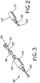
- a leak sensor calibrating device constructed in accordance with the teachings of the present invention is generally referred to by the reference numeral 10.
- the calibrating device 10 is typically placed closely adjacent to a gas sensor array (not shown), which in turn is typically placed closely adjacent to the system which is to be monitored for leakage, such as a valve, a pipe system or seal, or any other potential emission source (not shown).
- the device 10 includes a reservoir 12 which contains a quantity of analyte calibrant 14, which is preferably the same material as is running through the valve or other system component (not shown) to be monitored.
- the analyte calibrant 14 may be in either a liquid phase or in a vapor phase.
- the device 10 includes a body or housing 16 having a plurality of intersecting conduits or bores 18, 20 and 22.
- the housing 16 is preferably manufactured of stainless steel or other suitable materials.
- the bore 18 includes first and second sections 19, 21, respectively.
- the bore 18 extends substantially through the housing 16 and is in flow communication with the reservoir 12 and the bore 20.
- the bore 20 extends to the bore 18 and is in flow communication with an outlet nozzle 24.
- the outlet nozzle 24 will preferably be placed closely adjacent to the valve (or other system component) to be monitored for leakage (not shown).
- a bore 26 connects the bores 18 and 20, and defines a dosing chamber 28.
- the dosing chamber 28 is preferably of a predetermined volume.
- the volume of the dosing chamber 28 may be in the range of 2 microliters (2 x 10 -6 cubic centimeters).
- the volume of the dosing chamber 28 may be in the range of 500 microliters (500 x 10 -6 cubic centimeters).
- Other volumes may be contemplated, as long as the dosing chamber 28 stores the predetermined volume of calibrant 14.
- the desired amount or volume of calibrant 14 to be ejected from the outlet nozzle 24 may be chosen based on a number of factors, including the type, concentration, purity, and state (i.e., liquid or vapor) of the chosen calibrant, as well as the temperature, humidity, etc. of the surrounding environment, all of which would be well known to those of skill in the art.
- the desired amount of calibrant 14 to be ejected can be increased or decreased by changing the volume of the dosing chamber 28.
- a bore 30 connects the bore 22 with the dosing chamber 28, and an air supply inlet 32 intersects the bore 22.
- the air supply inlet is connected to a source of pressurized air (not shown), the purpose of which will be explained in greater detail below.
- the air is supplied from the supply source at approximately 3psig, with appropriate deviations therefrom being possible as would be contemplated by those skilled in the art.
- the device 10 includes a valving mechanism 34 which, as will be explained in greater detail below, is adapted to eject a desired quantity of calibrant 14 from the dosing chamber 28 through the outlet nozzle 24.
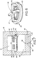
- the dosing chamber 28 includes an input end 36, an output end 38, and an intermediate portion 40 as shown in Fig. 5 .
- the bore 30 intersects the dosing chamber 28 at the intermediate portion 40.
- the input end 36 of the bore 26 may alternatively include a flared or conical portion 37.
- a check valve 39 is disposed in the portion 19 of the bore 18 generally adjacent to the input end 36 of the dosing chamber 28.
- the check valve 39 includes a housing 41 sized to be received in the portion 19 of the bore 21.
- the check valve 39 includes a plate or disc 43 which is sized to be received against a valve seat 45, and further includes a spring 47 for biasing the disc 43 toward a normally open position as shown in Fig. 7 .
- the portion 19 of the bore 18 may include an annular seat 49, enabling the check valve 39 to be pressed into place (for example, from below when viewing Fig. 7 ).
- the check valve 39 is thus operated automatically in response to the operation of the valving mechanism 34, and will further behave as a bi-stable check valve.
- the check valve 39 is preferably located slightly away from the input end 36 of the bore 26 so as to define a chamber 35.
- the volume of the reservoir 12 is preferably much greater than the volume of the dosing chamber 28, in order to facilitate rapid refilling of the dosing chamber 28 after the measured quantity stored therein has been ejected through the outlet nozzle.
- the volume of the reservoir 12 may be approximately twenty (20) times the volume of the dosing chamber 28.
- the valve mechanism 34 includes a first valve 42 disposed in the section 21 of the bore 18.
- the valve 42 includes a tip 44 adapted to close off the outlet end 38 of the dosing chamber 28.
- the valve mechanism 34 also includes a second valve 46 disposed in the bore 22 and having a tip 48 adapted to close off an inlet end 50 of the bore 30.
- Each of the valves 42 and 46 is shiftable between closed and open positions. When the valve 42 is in a closed position, the valve 42 isolates the dosing chamber 28 from the outlet nozzle 24. When the valve 42 is in an open position, the dosing chamber 28 is in flow communication with the outlet nozzle 24.
- each of the valves 42 and 46 is a remotely operable, electrically actuated microvalve. Still preferably, each of the valves 42, 46 are remotely operable from a common control system 52.
- the valve 42 includes a body 54, an electromagnetic bobbin 56, a pair of soft magnetic pole pieces 58, 60, a rare earth permanent magnet 62 an insulator 64 and an armature 66.
- the valve body 54, the pole pieces 58, 60, and the armature 66 are preferably constructed using 17-4 stainless steel, while the insulator 64 is preferably constructed of 316 stainless steel.
- the magnet 62 is preferably constructed of Nickel Iron Boron.
- the valves 42 and 46 are preferably electrically operable valves, having a six (6) volt actuation energy drawing 250mA at 10 milliseconds. Other suitable valves may be substituted.
- a Teflon ® insert 68 may be used at the intersection of the bores 18, 20 and 22.
- the Teflon insert 68 is preferably compression molded using known techniques, so as to have defined therein the dosing chamber 28 and the bore 30.
- the use of a separate insert 68 greatly eases the manufacturing process by permitting the housing 16 to be manufactured to a first set of tolerances, while the insert 68 is manufactured to a second, more rigorous set of tolerances.
- the insert 68 also provides a better seal at the tip 44 and 48 of the valves 42 and 46, respectively.
- the control system 52 first opens the valve 46, preferably for a period of 50 milliseconds. While the valve 46 is open, the control system 52 next opens the valve 42, which permits the pressurized air from the air source to flow through the air inlet 32. The resulting pressure increase causes the check valve 39 to immediately shift to its closed position. The incoming air acts to displace the measured quantity of calibrant 14 stored in the dosing chamber 28, causing the measured quantity to be ejected from the outlet nozzle 24.
- check valve 39 By virtue of the check valve 39 moving to its closed position upon the introduction of the actuation pressure, any flow of calibrant 14 from the dosing chamber 28 toward the reservoir 12 is prevented, and the calibrant 14 in the dosing chamber 28 is ejected out of the outlet nozzle 24. After the desired 10 millisecond interval, the valve 42 is closed. Shortly thereafter, valve 46 is closed. With the actuation pressure closed off, the check valve 39 returns to its normal open position aided by the force of the spring 47, and calibrant 14 is free to flow from the reservoir into the dosing chamber 28.
- the exhausted calibrant 14 is mixed with a known quantity of atmosphere from around a process system valve (not shown) for the purpose of measuring or predicting the leak emissions from the valve.
- the leak sensor (not shown) can be calibrated by comparing the obtained sensor reading to empirical data, or by using other known methods.
- the calibrant 14 in its vapor state.
- the potential for leakage at each of the valves 42, 46 is greatly minimized, especially when the device 10 is used in high temperature environments.
- the leak sensor (not shown) may be calibrated by taking into consideration the surrounding temperature and the vapor pressure of the calibrant in order to calculate the entrained quantity of calibrant ejected from the outlet nozzle 24.
- the present device 10 may be used in order to periodically test the constituency or purity of a substance flowing through a pipeline or other conveyance in an industrial process system (not shown).
- the reservoir 14 would be in constant flow communication with the substance flowing through the pipeline or system, and the outlet nozzle 24 would be placed in close proximity to an appropriate sensor.
- a leak sensor calibrating device 110 includes a reservoir 112 which contains a quantity of analyte calibrant 114.
- the device 110 includes a body or housing 116 having a plurality of intersecting conduits or bores 118, 120 and 122.
- the bore 118 includes first and second sections 119, 121, respectively, and extends substantially through the housing 116.
- the bore 120 extends to the bore 118 and is in flow communication with an outlet nozzle 124.
- a bore 126 connects the bores 118 and 120, and defines a dosing chamber 128.
- the dosing chamber 128 will store a predetermined volume of calibrant 14, with the predetermined or desired amount being determined by the internal volume of the dosing chamber 28.
- a bore 130 connects the bore 122 with the dosing chamber 128, and an air supply inlet 132 intersects the bore 122.
- the air supply inlet 132 is connected to a source of pressurized air, which is supplied from a supply source at approximately 3psig.
- the device 110 includes a valving mechanism 134 having a first valve 142 disposed in the section 121 of the bore 118 and further having a tip 144 adapted to close off the outlet end 138 of the dosing chamber 128.
- the valve mechanism 134 also includes a second valve 146 disposed in the bore 122 and having a tip 148 adapted to close off an inlet end 150 of the bore 130.
- the valving mechanism 134 is operable in a manner similar to that described above with respect to the first preferred embodiment.
- the dosing chamber 128 includes an input end 136, an output end 138, and an intermediate portion 140.
- the bore 130 intersects the dosing chamber 128 at the intermediate portion 140.
- the bore 18 includes a section 139, with the section 139 being disposed adjacent the input end 136 of the dosing chamber 128.
- the section 139 has a diameter greater than the diameter of the dosing chamber 128, such that the section 139 functions as a pneumatic restriction.
- the bore 118 is shown as having two sections of different diameter, the bore 118 alternatively may be of uniform diameter, as long as the cross-sectional area of the section 139 immediately adjacent to the input end 136 of the dosing chamber 128 is significantly greater than the cross-sectional area of the dosing chamber 128.
- the reservoir may instead be piping system containing a process stream of a fluid material, and the device may be employed to periodically sample the purity or the constituency of the process stream by ejecting a known quantity of the fluid material to a sensing device.
Landscapes
- Physics & Mathematics (AREA)
- General Physics & Mathematics (AREA)
- Chemical & Material Sciences (AREA)
- Engineering & Computer Science (AREA)
- Fluid Mechanics (AREA)
- Health & Medical Sciences (AREA)
- Life Sciences & Earth Sciences (AREA)
- Biochemistry (AREA)
- Medicinal Chemistry (AREA)
- Analytical Chemistry (AREA)
- Food Science & Technology (AREA)
- General Health & Medical Sciences (AREA)
- Immunology (AREA)
- Pathology (AREA)
- Combustion & Propulsion (AREA)
- Sampling And Sample Adjustment (AREA)
- Examining Or Testing Airtightness (AREA)
- Measuring Volume Flow (AREA)
- Feeding, Discharge, Calcimining, Fusing, And Gas-Generation Devices (AREA)
- Infusion, Injection, And Reservoir Apparatuses (AREA)
Applications Claiming Priority (3)
| Application Number | Priority Date | Filing Date | Title |
|---|---|---|---|
| US287245 | 1988-12-21 | ||
| US09/287,245 US6408674B1 (en) | 1999-04-07 | 1999-04-07 | Pressure activated calibration system for chemical sensors |
| PCT/US2000/007943 WO2000060320A1 (en) | 1999-04-07 | 2000-03-23 | Pressure activated calibration system for chemical sensors |
Publications (2)
| Publication Number | Publication Date |
|---|---|
| EP1169621A1 EP1169621A1 (en) | 2002-01-09 |
| EP1169621B1 true EP1169621B1 (en) | 2017-08-23 |
Family
ID=23102063
Family Applications (1)
| Application Number | Title | Priority Date | Filing Date |
|---|---|---|---|
| EP00918395.5A Expired - Lifetime EP1169621B1 (en) | 1999-04-07 | 2000-03-23 | Leak sensor calibration device |
Country Status (9)
| Country | Link |
|---|---|
| US (1) | US6408674B1 (enExample) |
| EP (1) | EP1169621B1 (enExample) |
| JP (1) | JP4554823B2 (enExample) |
| CN (2) | CN1183376C (enExample) |
| AU (1) | AU3921500A (enExample) |
| BR (1) | BR0009589B1 (enExample) |
| CA (1) | CA2369928C (enExample) |
| MX (1) | MXPA01010076A (enExample) |
| WO (1) | WO2000060320A1 (enExample) |
Families Citing this family (4)
| Publication number | Priority date | Publication date | Assignee | Title |
|---|---|---|---|---|
| AU2003287375A1 (en) * | 2002-10-31 | 2004-06-07 | Advanced Calibration Designs, Inc. | Apparatus and method to calibrate a gas detector |
| US7594422B2 (en) * | 2006-10-30 | 2009-09-29 | Ge Homeland Protection, Inc. | Apparatus and method for calibrating a trace detection portal |
| CN101496997B (zh) * | 2009-01-14 | 2011-04-13 | 管雷全 | 尿素计量喷射装置 |
| CN102692257B (zh) * | 2012-06-08 | 2013-12-18 | 吉林市光大分析技术有限责任公司 | 气动液体定量方法及其装置 |
Citations (2)
| Publication number | Priority date | Publication date | Assignee | Title |
|---|---|---|---|---|
| US5402913A (en) * | 1992-12-05 | 1995-04-04 | Satzinger Gmbh & Co. | Apparatus for the metered dispensing of a flowable medium, especially a lubricant |
| US5742523A (en) * | 1993-12-24 | 1998-04-21 | Seva | Method and device for supplying gas under pressure |
Family Cites Families (24)
| Publication number | Priority date | Publication date | Assignee | Title |
|---|---|---|---|---|
| US3290920A (en) | 1964-02-07 | 1966-12-13 | United States Steel Corp | Apparatus for calibrating vapor responsive detectors |
| GB1178202A (en) | 1967-04-17 | 1970-01-21 | Euratom | Apparatus for use in Calibration of Leak Detectors |
| LU55734A1 (enExample) | 1967-04-17 | 1968-06-04 | ||
| US3760773A (en) | 1972-03-06 | 1973-09-25 | Envirotech Corp | Gas generating and metering device and method |
| US4064572A (en) * | 1976-05-19 | 1977-12-27 | Shell Oil Company | Level actuated apparatus for delivering chemicals |
| DE2702002A1 (de) | 1977-01-19 | 1978-07-20 | Leybold Heraeus Gmbh & Co Kg | Fluessiggas-testleck |
| US4164861A (en) | 1978-02-17 | 1979-08-21 | Inficon Leybold-Heraeus Inc. | Leak standard generator |
| US4462760A (en) | 1978-04-14 | 1984-07-31 | Orbital Engine Company Proprietary Limited | Method and apparatus for metering liquids |
| US4343176A (en) | 1980-11-12 | 1982-08-10 | The United States Of America As Represented By The United States Department Of Energy | Long-life leak standard assembly |
| PH20932A (en) | 1981-12-31 | 1987-06-05 | Orbital Engine Comp Proprietar | Liquid metering apparatus |
| US4713618A (en) | 1985-10-02 | 1987-12-15 | Westinghouse Electric Corp. | On-line calibration system for chemical monitors |
| US4742708A (en) | 1986-08-13 | 1988-05-10 | Beckman Industrial Corporation | Apparatus for electrochemical sensor calibration |
| US5185263A (en) | 1987-10-23 | 1993-02-09 | Avl Medical Instruments Ag | Method for calibration of a measurement apparatus |
| CN88210847U (zh) * | 1988-03-01 | 1988-11-09 | 山东省计量科学研究所 | 液体定值计量装置 |
| US5028394A (en) | 1990-04-13 | 1991-07-02 | Bend Research, Inc. | Chemical sensors |
| US5094958A (en) | 1990-08-30 | 1992-03-10 | Fiberchem Inc. | Method of self-compensating a fiber optic chemical sensor |
| US5447688A (en) | 1991-12-30 | 1995-09-05 | Moore; Robert E. | Detector, and method of using same |
| US5262127A (en) | 1992-02-12 | 1993-11-16 | The Regents Of The University Of Michigan | Solid state chemical micro-reservoirs |
| US5363689A (en) | 1992-09-11 | 1994-11-15 | Intertech Development Company | Calibration device for leak detecting instruments |
| BR9406171A (pt) * | 1993-04-16 | 1996-01-09 | Kronseder Maschf Krones | Dispositivo giratório para encher porções de liquidos em garrafas latas ou receptáculos similares |
| US5493890A (en) | 1994-03-16 | 1996-02-27 | Thermedics Detection Inc. | Apparatus and method for calibrating vapor/particle detection devices |
| US5550053A (en) | 1995-01-05 | 1996-08-27 | Si Industrial Instruments, Inc. | Method of calibrating an automatic chemical analyzer |
| CN1139754A (zh) * | 1995-07-04 | 1997-01-08 | 张金华 | 定量气力输送设备 |
| US5970778A (en) * | 1997-11-12 | 1999-10-26 | Fisher Controls International | Thermally activated calibration system for chemical sensors |
-
1999
- 1999-04-07 US US09/287,245 patent/US6408674B1/en not_active Expired - Lifetime
-
2000
- 2000-03-23 CN CNB00807948XA patent/CN1183376C/zh not_active Expired - Lifetime
- 2000-03-23 AU AU39215/00A patent/AU3921500A/en not_active Abandoned
- 2000-03-23 JP JP2000609767A patent/JP4554823B2/ja not_active Expired - Fee Related
- 2000-03-23 CA CA2369928A patent/CA2369928C/en not_active Expired - Lifetime
- 2000-03-23 EP EP00918395.5A patent/EP1169621B1/en not_active Expired - Lifetime
- 2000-03-23 BR BRPI0009589-3A patent/BR0009589B1/pt active IP Right Grant
- 2000-03-23 CN CNB2004100927324A patent/CN100405026C/zh not_active Expired - Lifetime
- 2000-03-23 MX MXPA01010076A patent/MXPA01010076A/es active IP Right Grant
- 2000-03-23 WO PCT/US2000/007943 patent/WO2000060320A1/en not_active Ceased
Patent Citations (2)
| Publication number | Priority date | Publication date | Assignee | Title |
|---|---|---|---|---|
| US5402913A (en) * | 1992-12-05 | 1995-04-04 | Satzinger Gmbh & Co. | Apparatus for the metered dispensing of a flowable medium, especially a lubricant |
| US5742523A (en) * | 1993-12-24 | 1998-04-21 | Seva | Method and device for supplying gas under pressure |
Also Published As
| Publication number | Publication date |
|---|---|
| CA2369928A1 (en) | 2000-10-12 |
| CN1351708A (zh) | 2002-05-29 |
| BR0009589B1 (pt) | 2013-04-16 |
| JP2002541447A (ja) | 2002-12-03 |
| WO2000060320A1 (en) | 2000-10-12 |
| CN1782677A (zh) | 2006-06-07 |
| BR0009589A (pt) | 2002-02-05 |
| US6408674B1 (en) | 2002-06-25 |
| AU3921500A (en) | 2000-10-23 |
| JP4554823B2 (ja) | 2010-09-29 |
| EP1169621A1 (en) | 2002-01-09 |
| CN1183376C (zh) | 2005-01-05 |
| CA2369928C (en) | 2010-11-02 |
| MXPA01010076A (es) | 2002-07-30 |
| CN100405026C (zh) | 2008-07-23 |
Similar Documents
| Publication | Publication Date | Title |
|---|---|---|
| US6581623B1 (en) | Auto-switching gas delivery system utilizing sub-atmospheric pressure gas supply vessels | |
| US6689621B2 (en) | Fluid dispensing system and valve control | |
| US6997202B2 (en) | Gas storage and dispensing system for variable conductance dispensing of gas at constant flow rate | |
| US20020157446A1 (en) | Pressure activated calibration system for chemical sensors | |
| US7387135B2 (en) | Valve assembly having rigid seating surfaces | |
| US20040020938A1 (en) | Fluid dispensing device | |
| EP1169621B1 (en) | Leak sensor calibration device | |
| US5970778A (en) | Thermally activated calibration system for chemical sensors | |
| US7484399B2 (en) | System, apparatus and method for dispensing chemical vapor | |
| US3368385A (en) | Sample system for chromatographic analyzers | |
| US20050112020A1 (en) | Ultrasonic and sonic odorization systems | |
| US20230266156A1 (en) | Method and Apparatus for Pressure Based Mass Flow Control | |
| WO2004041973A1 (en) | Optical odorization system | |
| MXPA00004604A (en) | Thermally activated calibration system for chemical sensors | |
| US20030021731A1 (en) | System for automatically extracting and analysing residual solvents in material samples | |
| Basford | Recommended practices for the calibration and use of leaks | |
| JPH05240679A (ja) | 圧力平衡化システム及びバルブ |
Legal Events
| Date | Code | Title | Description |
|---|---|---|---|
| PUAI | Public reference made under article 153(3) epc to a published international application that has entered the european phase |
Free format text: ORIGINAL CODE: 0009012 |
|
| 17P | Request for examination filed |
Effective date: 20011106 |
|
| AK | Designated contracting states |
Kind code of ref document: A1 Designated state(s): AT BE CH CY DE DK ES FI FR GB GR IE IT LI LU MC NL PT SE |
|
| RBV | Designated contracting states (corrected) |
Designated state(s): DE FI FR GB SE |
|
| RAP1 | Party data changed (applicant data changed or rights of an application transferred) |
Owner name: FISHER CONTROLS INTERNATIONAL LLC |
|
| 17Q | First examination report despatched |
Effective date: 20041201 |
|
| REG | Reference to a national code |
Ref country code: DE Ref legal event code: R079 Ref document number: 60049694 Country of ref document: DE Free format text: PREVIOUS MAIN CLASS: G01F0011280000 Ipc: G01M0003000000 |
|
| GRAP | Despatch of communication of intention to grant a patent |
Free format text: ORIGINAL CODE: EPIDOSNIGR1 |
|
| RIC1 | Information provided on ipc code assigned before grant |
Ipc: G01M 3/00 20060101AFI20170302BHEP Ipc: G01N 33/00 20060101ALN20170302BHEP Ipc: G01F 25/00 20060101ALI20170302BHEP Ipc: G01F 11/28 20060101ALI20170302BHEP |
|
| INTG | Intention to grant announced |
Effective date: 20170314 |
|
| GRAS | Grant fee paid |
Free format text: ORIGINAL CODE: EPIDOSNIGR3 |
|
| GRAA | (expected) grant |
Free format text: ORIGINAL CODE: 0009210 |
|
| AK | Designated contracting states |
Kind code of ref document: B1 Designated state(s): DE FI FR GB SE |
|
| REG | Reference to a national code |
Ref country code: GB Ref legal event code: FG4D |
|
| REG | Reference to a national code |
Ref country code: DE Ref legal event code: R096 Ref document number: 60049694 Country of ref document: DE |
|
| PG25 | Lapsed in a contracting state [announced via postgrant information from national office to epo] |
Ref country code: FI Free format text: LAPSE BECAUSE OF FAILURE TO SUBMIT A TRANSLATION OF THE DESCRIPTION OR TO PAY THE FEE WITHIN THE PRESCRIBED TIME-LIMIT Effective date: 20170823 Ref country code: SE Free format text: LAPSE BECAUSE OF FAILURE TO SUBMIT A TRANSLATION OF THE DESCRIPTION OR TO PAY THE FEE WITHIN THE PRESCRIBED TIME-LIMIT Effective date: 20170823 |
|
| REG | Reference to a national code |
Ref country code: FR Ref legal event code: PLFP Year of fee payment: 19 |
|
| REG | Reference to a national code |
Ref country code: DE Ref legal event code: R097 Ref document number: 60049694 Country of ref document: DE |
|
| PLBE | No opposition filed within time limit |
Free format text: ORIGINAL CODE: 0009261 |
|
| STAA | Information on the status of an ep patent application or granted ep patent |
Free format text: STATUS: NO OPPOSITION FILED WITHIN TIME LIMIT |
|
| 26N | No opposition filed |
Effective date: 20180524 |
|
| REG | Reference to a national code |
Ref country code: DE Ref legal event code: R119 Ref document number: 60049694 Country of ref document: DE |
|
| PG25 | Lapsed in a contracting state [announced via postgrant information from national office to epo] |
Ref country code: DE Free format text: LAPSE BECAUSE OF NON-PAYMENT OF DUE FEES Effective date: 20181002 |
|
| PGFP | Annual fee paid to national office [announced via postgrant information from national office to epo] |
Ref country code: FR Payment date: 20190325 Year of fee payment: 20 |
|
| PGFP | Annual fee paid to national office [announced via postgrant information from national office to epo] |
Ref country code: GB Payment date: 20190404 Year of fee payment: 20 |
|
| REG | Reference to a national code |
Ref country code: GB Ref legal event code: PE20 Expiry date: 20200322 |
|
| PG25 | Lapsed in a contracting state [announced via postgrant information from national office to epo] |
Ref country code: GB Free format text: LAPSE BECAUSE OF EXPIRATION OF PROTECTION Effective date: 20200322 |